
How to read connector plans on Yamaha wiring loom?
TimC - 5/7/18 at 06:52 AM
Good Morning All,
I’ve got to wire a new connector for the original Yamaha clocks - I’m doing this to read fault codes.
Rather than spend Ł50ish+ on a clock loom, I’ve managed to buy a new plug with terminals for Ł6 that I just need to wire.
If I look at the diagram, I see this:
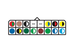
Clock Plug
What I want to know is, does the diagram reflect the plug as I push the terminals in from the back? Or, is it as viewed from the connecting end of
the plug?
Any help appreciated.
Cheers,
T
Davg - 5/7/18 at 07:14 AM
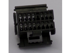
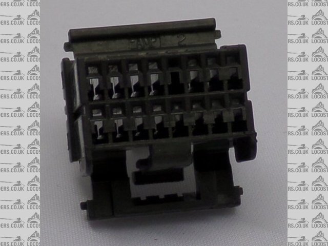
Hi Tim your pic is view from front of plug . So wires inserted to back. Cheers D
TimC - 5/7/18 at 07:22 AM
quote:
Originally posted by Davg
Hi Tim your pic is view from front of plug . So wires inserted to back. Cheers D
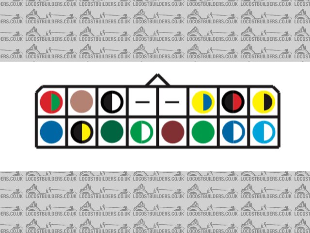
Thank you. Just to be absolutely clear, then - as I look at this:
Plug
bottom right will be light blue with a white tracer?
Davg - 5/7/18 at 07:31 AM
Can't see this pic too clearly. Whether this is the back or front of plug. Blue/Wh will be neutral and when plug is in clocks looking into back
of clocks will be bottom left.
Davg - 5/7/18 at 11:21 AM
Tim just for total clarification, your first pic with colour codes of plug is upside down when you insert into clocks the tab is at the bottom.
The pins are actually numbered 1-16 So viewing the plug from the back as you would be inserting into clocks should be pin 1 bottom left red/green
pin 8 bottom right yell/blk
Pin 9 top left blue
Pin 16 top right blue/wh with others per pic. Assume you know what the colours relate to. Cheers D
TimC - 5/7/18 at 12:57 PM
Great - thanks so much for taking the time to walk me through this.
Yes - I know what colours I need - I just wasn’t sure where to put them and didn’t want to fry my new (to me) clocks finding out.
Thanks again
adithorp - 5/7/18 at 01:41 PM
Don't forget you need the kill switch as well to access the fault codes and test facilities.

