Just out of interest I looked at the projected weight, I think I’m heading for about 75kg for the chassis does this sound about right?
[Edited on 28/12/10 by orton1966]
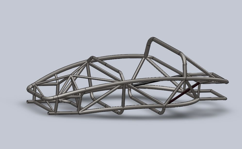
I’m currently finalising my midi design and drawing it up in solidworks. One of the aspects that’s always concerned me about some exo-midi’s is
relatively poor triangulations so I’m currently trying to satisfy myself whilst still keeping the ‘exo’ look.
Just out of interest I looked at the projected weight, I think I’m heading for about 75kg for the chassis does this sound about right?
[Edited on 28/12/10 by orton1966]
that bit at the front will be tricky to make, to say the least 
75Kg is exactly the weight of the Furore chassis, the Furore is quite a large car, but obviously tandem seating saves some weight so shorter & wider I'd say you're about spot on - that front end with all the tubes coming together at a single point is identical to MNR's lmp car & they seem to manage it without a problem!
Square tube striker chassis including braced rollbar comes in at 62kg.
Striker is considered to be pretty light (in an oldskool way)
Just an observation, the chassis as shown has no bracing to the lower engine bay & would be very weak - particularly if you were mounting
suspension to those tubes!
It also seems to be missing the curved tube on the Drivers side going from the bottom of the roll car to the rear edge of the cube.
quote:
Originally posted by loggyboy
It also seems to be missing the curved tube on the Drivers side going from the bottom of the roll car to the rear edge of the cube.

If possible make the floor to go on the floor and around the sides to the lower chassis rails (making a large 'u' shape). This will add a lot of strenght but i've no idea how you'd do it practically using sandwich composite.
quote:
Originally posted by MikeR
If possible make the floor to go on the floor and around the sides to the lower chassis rails (making a large 'u' shape). This will add a lot of strenght but i've no idea how you'd do it practically using sandwich composite.
your nearside lower rail seems to curve in 2 planes. is that odd solidworks perspective or the actual shape of the spline? i'd try make it single
radius/single plane bends to aid fabrication if i were you. istr nitram had enough trouble getting anyone to ring roll his rails with a change in
radius
are you using weldments in solidworks? if not, the tutorial's thorough and easy to follow. it's good to give you an idea of the final shape
of tubes and will tidy up a few of your overlaps. also useful if you want your tubes laser profiling dependent on budget 
i know the spider brace at the front may be a design feature, but have you considered making it primarily an X to tie the rearmost front wishbone
uprights together and then working back to the node in the x?
not sure why you've gone so high with it (pedal box clearance?) but surely it'd be stiffer if at least one x was working in plane. it'd
help stop the front box lozenging too, though i imagine it's imperceptible stiffness gains.
finally, can we have some more ortho views of it please? i like stuff like this. one of my christmas jobs is to start reworking our formula student
spaceframe for the electric car.
tom
Thanks for the input. I’m pretty new to solid works, the model is built with weldments but I haven’t played with trimming tube ends etc. so I’ll give
the tutorial a go.
The top and bottom main-tubes both feature two radius but each of these is only rolled in one dimension, although the plane they sit on in the model
differ (forward and rearward of the roll-hoop) giving the corkscrew effect. I’m relatively happy with the top one but at certain angles the bottom one
doesn’t quite flow right. I think increasing the angle will improve things effectively this means lowering the rear end of the chassis, I might try
putting up a before and after pic so people can judge the result.
There are a few things that aren’t finally dimensioned yet, some are just down to making final decisions, cockpit width/length. Some hinges on other
modelling, front and rear suspension and others are about playing until it looks right. The thought about the height of that area of tube joints is
that this can also support the ‘bonnet/front panel’ (for want of a better word) but it might also become a central shock mounting for the pushrod
suspension so its height and position might change a little with that
quote:
Originally posted by indykid
your nearside lower rail seems to curve in 2 planes. is that odd solidworks perspective or the actual shape of the spline? i'd try make it single radius/single plane bends to aid fabrication if i were you. istr nitram had enough trouble getting anyone to ring roll his rails with a change in radius
are you using weldments in solidworks? if not, the tutorial's thorough and easy to follow. it's good to give you an idea of the final shape of tubes and will tidy up a few of your overlaps. also useful if you want your tubes laser profiling dependent on budget
i know the spider brace at the front may be a design feature, but have you considered making it primarily an X to tie the rearmost front wishbone uprights together and then working back to the node in the x?
not sure why you've gone so high with it (pedal box clearance?) but surely it'd be stiffer if at least one x was working in plane. it'd help stop the front box lozenging too, though i imagine it's imperceptible stiffness gains.
finally, can we have some more ortho views of it please? i like stuff like this. one of my christmas jobs is to start reworking our formula student spaceframe for the electric car.
tom

With floor, all braces and brackets you won't beat 100kgs.
Hope you have the suspension - damper pickups sorted as without this it's it kinda putting the cart before the horse.
Looks nice though, the point at which you have 7 tubes coming together will need sorting, either done away with somehow or a fixture put in there for
the tubes to weld onto, as that situation will be a PITA to do.
I weighed mine today with suspension, axles, brakes but no calipers and 3 wheels bolted on and got 150kgs.
Quite happy, am on target for my hoped for 500kgs with 2 litre engine.