
Crank Rotation / Rod Movement
AntonUK - 1/9/15 at 06:41 PM
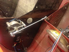
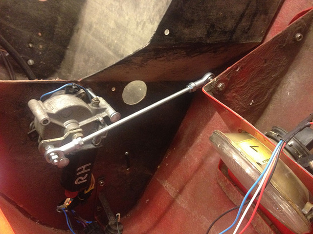
Im trying to improve the open / close mechanism for my pop up headlights. Im using standard Mk1 MX5 motors which rotate 180 degrees (always the same
direction) depending on which wire you put 12v. So open-close-open would rotate a full 360.
The current crank fitted to the mx5 motors is 37mm between centres. Which is then connected to a rod connecting the end of the crank to the back of
the headlamp pod.
The light pods need 125mm of movement from open to closed.
Im trying to calculate the correct required crank length to remove a bind point which I currently have a problem with, But the maths is baffling, and
to be honest I don't know where to start. Initially i though the crank just needed to be half of the required movement but that appears to be too
big. I think this is to do with the offset between the two point.
HELP? Anyone?
Description

Description

Description
AntonUK - 1/9/15 at 08:28 PM
So I've narrowed it down to the fact I need to use 'offset crank slider mechanism' type calculations but the maths if way over my
head...
OliilO - 1/9/15 at 08:36 PM
Make a model out of cardboard and experiment with different sizes?
daviep - 1/9/15 at 08:41 PM
I think to begin with you need to know a few lengths :-
1, Head lamp pivot point to where the rod is joined on
2, Length of push rod
3, Angle that headlamp needs to turn through
Not 100% sure but I'm thinking about it 
Cheers
Davie
Angel Acevedo - 1/9/15 at 10:55 PM
Draw two overlapping triangles, one would be pivot.
Base of smaller, two points determined by opposite dead centers of crank.
Base of bigger is the required fixing point of body to be actuated on full movement extremes.
In spanish "Triangulos Semejantes".
I hope this helps.
Angel Acevedo - 1/9/15 at 11:01 PM
After studying the pics a little bit more, can´t you direct actuate the housing by moving the motor closer to the fulcrum?
With that and a spring loaded actuating arm to remove play at each end of travel may do the trick.
TheGecko - 2/9/15 at 08:03 AM
What you have is an example of a 4-bar linkage (wikipedia article) which have some well
defined methods of analysis. There's a free linkage design tool at
http://blog.rectorsquid.com/linkage-mechanism-designer-and-simulator/
which may be helpful in understanding what's going on.
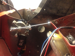
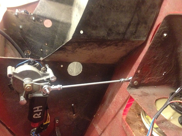
The main thing that catches my eye is the closed position with all four of the pivot points (motor axle; crank end; push rod end; headlight pivot) in
a single line - begging for bind-up. Shift the motor so that they're not aligned like that and you may well see an improvement.
Best of luck and let us know the outcome
Dominic


