Fred W B
|
| posted on 29/1/13 at 04:22 PM |

|
|
Yes, it would need some sort of offset bracket off the 2 holes in the bottom of the upright, or make a complete new upright around the bearing cup.
Cheers
Fred
[Edited on 29/1/13 by Fred W B]
You can do it quickly. You can do it cheap. You can do it right. Pick any two.
|
|
|
|
|
b14wrc
|
| posted on 30/1/13 at 12:22 PM |
|
|
Humm, i wonder if i could make a baket to bolt the shock to the hub, the drive shaft would get in the way, but if i coud use a spacer, it might
work...... 
20vt powered rear engined locost
|
|
|
britishtrident
|
| posted on 30/1/13 at 08:11 PM |
|
|
quote:
Originally posted by b14wrc
Humm, i wonder if i could make a baket to bolt the shock to the hub, the drive shaft would get in the way, but if i coud use a spacer, it might
work......
That would result in a pretty big twisting moment on to the hub and the way it appears to me in a number of ways the whole concept is already
close to or on limits of what will safely hang together.
I advise stop fabricating for a few days and have think about the direction this layout is taking you, and consider the conventional path of using
uprights based on Sierra "ears" .
As an alternative to wishbone layouts used on Sierra based Locosts you might also like to look at the rears suspension layout used on late 1960s
F1 cars and sports racers for example the Lotus 33 or 49 any of Len Terry's cars of that era.
[I] What use our work, Bennet, if we cannot care for those we love? .
― From BBC TV/Amazon's Ripper Street.
[/I]
|
|
|
b14wrc
|
| posted on 31/1/13 at 12:03 PM |
|
|
Thanks for the input.
Could you explain to me why my design is already on the limits? As far as i can see, its fairly similar to any other.
As for using the sierra hubs, which will give me a massive issue with the fiat hubs, fiat hubs have 26 splines on the drive shaft and fords run 25 or
27 as far as i have looked. Plus the length probably will be all wrong. I am not really sure what addvantages i would get.
I am looking for constructive criticism with this as Im not a mechanical engineer.

Rob
20vt powered rear engined locost
|
|
|
mark chandler
|
| posted on 31/1/13 at 12:29 PM |
|
|
This is my rear setup, no issues in maybe 5 years, only tracked on slicks so it does get a pounding.

Although not clear in the picture the bone spans both sides of the hub with a single bolt going through the hub with a rose joint either side
(it's a mirror image) with a diagonal to brace the bone.
I have to run heavy springs due to the working ratio.
My load is spread across 2 x rose joints and I adjust by twiddling the two lower ones, I guess the concern is that if you land the shock on the bone
then all the weight will be taking on only 1 rose joint so you will have a lot of force here.
If you land the shock on the hub then all the weight is directly on the hub so the bone is just spacing out the hub and taking the turning torque.
The latter is preferred but build restrictions change the game, in my case I am happy although this is based upon if it looks right it's
probably right without any calls.
Regards Mark
[Edited on 31/1/13 by mark chandler]
|
|
|
britishtrident
|
| posted on 31/1/13 at 10:35 PM |
|
|
The aspect that most concerns me on the design is the bolt on arrangement that controls the toe I really can't see that surviving even light
contact with a kerb.
As somebody wisely suggested earlier you have to think in terms of triangles not squares so that the forces within the wishbone or other part
should act along its axis either compress or stretch a tube not bend it and avoid nasty bending stresses don't occur at the corners.
Another problem is you say you have positive camber as the suspension compresses as would due to body roll -- the outside wheels in a corner
should have camber gain ie increasing negative camber to compensate for body roll. Using an upside down strut bottom isn't the best start to
achieve this.
Mark Chandler's rear end is nice example of typical accepted practice.
[I] What use our work, Bennet, if we cannot care for those we love? .
― From BBC TV/Amazon's Ripper Street.
[/I]
|
|
|
b14wrc
|
| posted on 2/2/13 at 02:19 PM |
|
|
Hi,
Thanks for most of the comments guys.
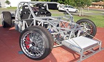
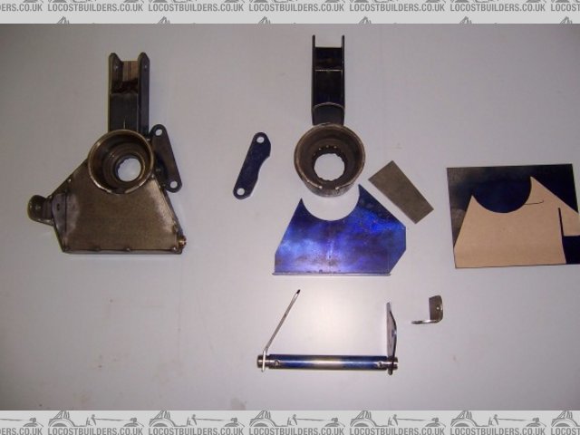
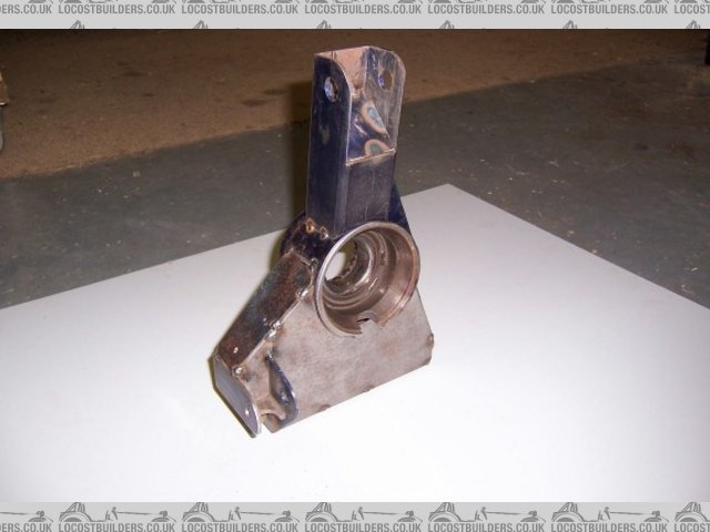
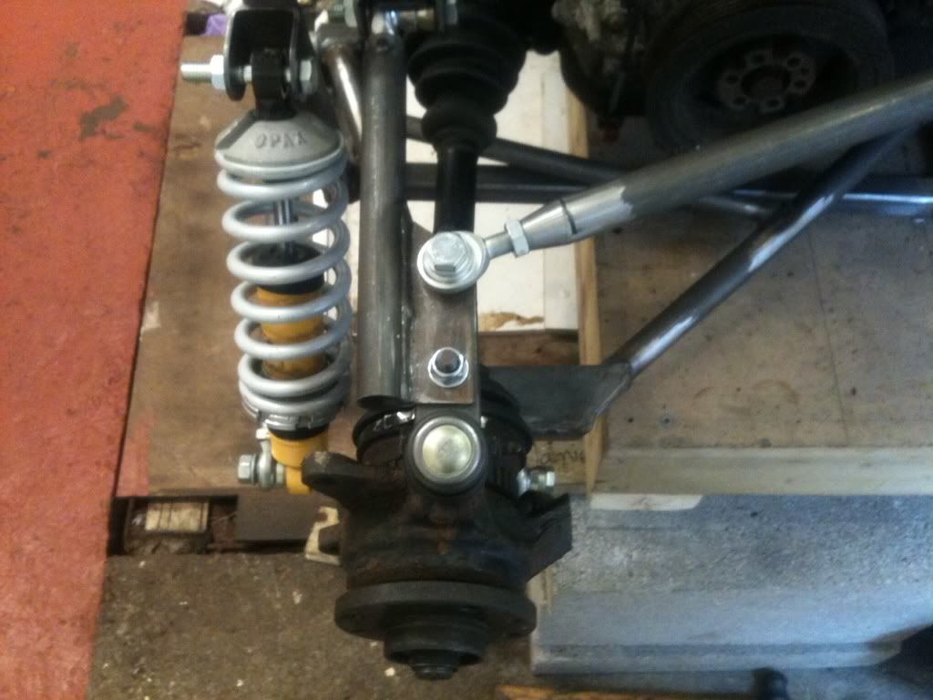
Last night I made up my brackets to hold the hub:
As a comparison, please see the Sylvia Mojo bottom arm, I based my design around that.
I am considering welding a tube onto the arm to replace the rose joint if people think that will improve the design. As I said, still got a few bits
to work on.
BT - I mentioned earlier about my pos neg camber mix up. I'm fully aware that during roll in a corner additional positive camber would give a
decrease in contact patch, not what I would want. Think that issue is sorted.
I also disagree that the toe control design is weak, I have seen many cars use similar. I would like to know exactly what it is you are concerned with
regarding it?? It isn't fully welded yet either!
I'm a big enough boy to be told I'm wrong, better to get it right now rather than later.
The triangle thing does bug me a bit, that steel plate on the end means that the arm is very unlikely to twist, so I don't really see it being
an issue, Marks is the same pretty much as the two rose joints fix to a flat out board end...
Thanks mark for your input, I like your set up and knowing it lasted 5 years of track abuse really helps me!
Rob
20vt powered rear engined locost
|
|
|
fregis
|
| posted on 2/2/13 at 02:53 PM |
|
|
in my opinion too weak upper part, need connect both sides. But flip sides would maybe be better? get used toe rod out there where you belong
http://images54.fotki.com/v461/photos/1/1313721/11631039/null3-vi.jpg
[Edited on 2/2/13 by fregis]
Never be afraid to do what you are insolvent, remember: amateurs built the ark - Professionals built the Titanic.
|
|
|
adithorp
|
| posted on 2/2/13 at 07:17 PM |
|
|
I'm no suspension design expert but...
That tube that the "toe bar" is attached to will bend on the first pot hole or curb.
I'd be surprised if it didn't bend just dumping the clutch.
[Edited on 2/2/13 by adithorp]
"A witty saying proves nothing" Voltaire
http://jpsc.org.uk/forum/
|
|
|
b14wrc
|
| posted on 2/2/13 at 07:47 PM |
|
|
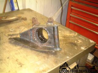
It has a stainless steel tube inside it by the way. Going to add a small plate across the tubes to add stiffness and have something to join the brake
pipes to.
Going to start again with the A Arms I've decided, will let you see my rethink as I go.
Rob
20vt powered rear engined locost
|
|
|
Doug68
|
| posted on 3/2/13 at 02:36 AM |
|
|
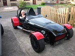
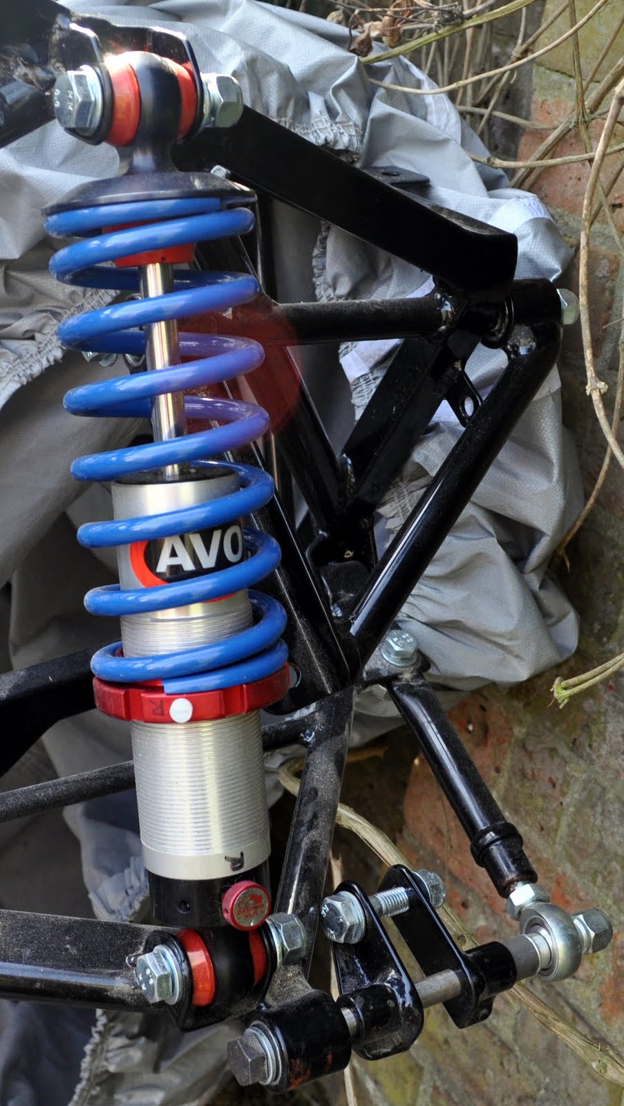
By way of reference here's some pictures of the Mojo rear suspension.
It's not how I'd choose to do it, but that's neither here nor there if its been proven to be sound in practice.


Doug. 1TG
Sports Car Builders WA
|
|
|
b14wrc
|
| posted on 3/2/13 at 11:16 AM |
|
|
Thanks Doug,
Yes, I have seen that. Why would you not choose to do it that way? For me, using the fiat hubs was almost essential as my car is a midi.
Like I said, on the advice given I'm going to scrap the bottom A arm and redo to eliminate the use of a rose joint and make it a proper
triangle.
Rob
20vt powered rear engined locost
|
|
|
b14wrc
|
| posted on 11/2/13 at 07:56 PM |
|
|
Hi Guys,
Not redone my A Arms yet, too much work on at the moment to get on with so not really been in the garage, however I did buy this:
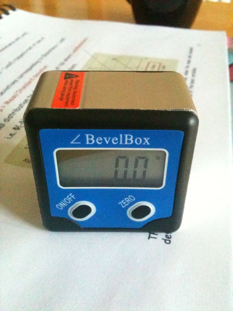
Nice little device, used it to rougthly check my current static camber settings.
The graph shows the NEGATIVE camber gain:
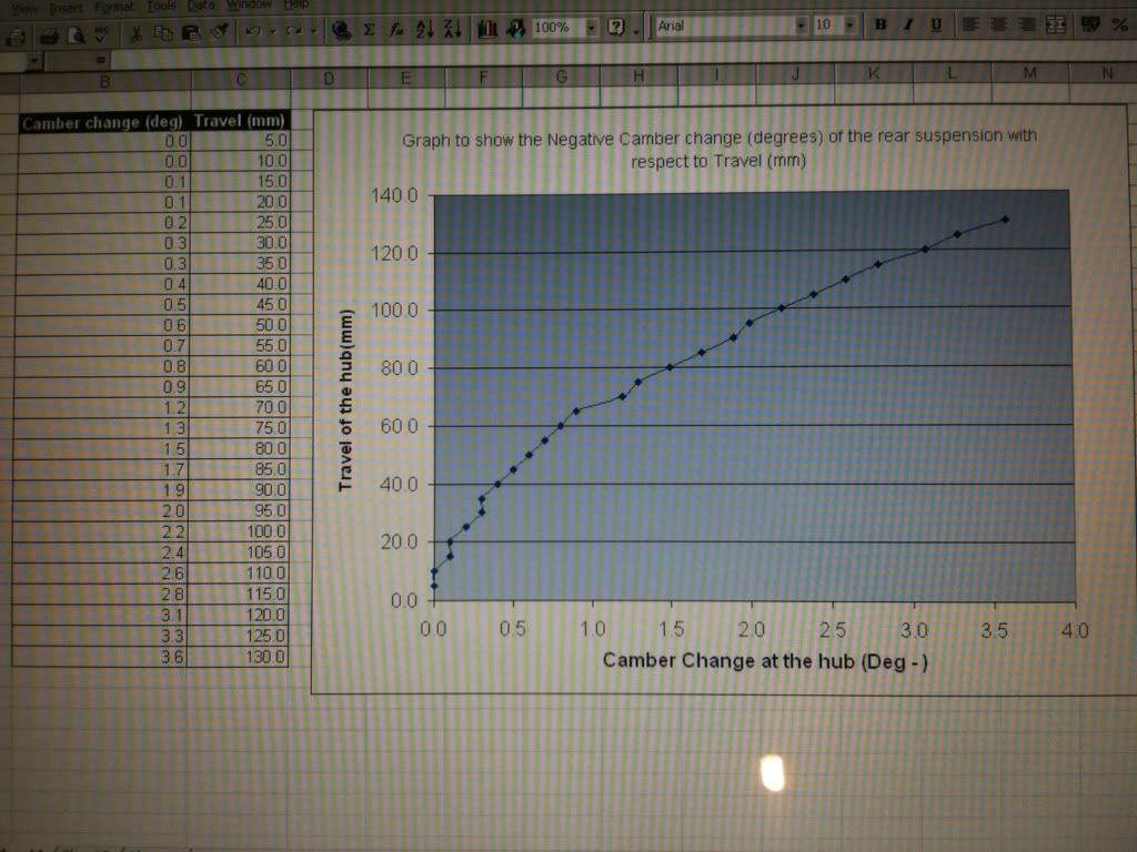
Question is, what do you all think of the amount of gain? Rembering that the bushes are not made yet and it's not all bolted up correctly,
it's a rough guild....
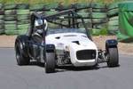
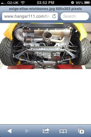
Also, just a pic of a lotus elise using toe control arms similar to my design.
Rob
20vt powered rear engined locost
|
|
|
b14wrc
|
| posted on 23/2/13 at 02:39 PM |
|
|
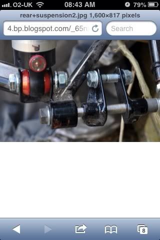
Hi all,
I am thinking about arranging my shock something like this:
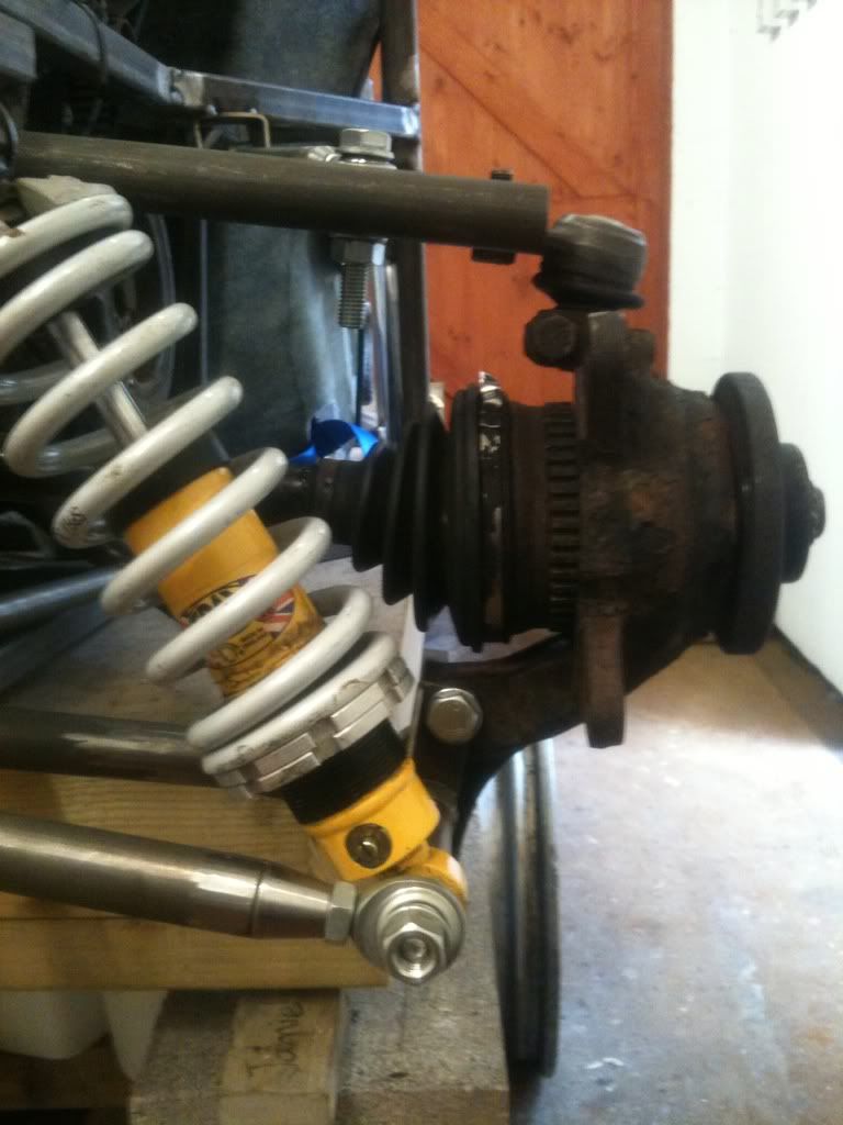
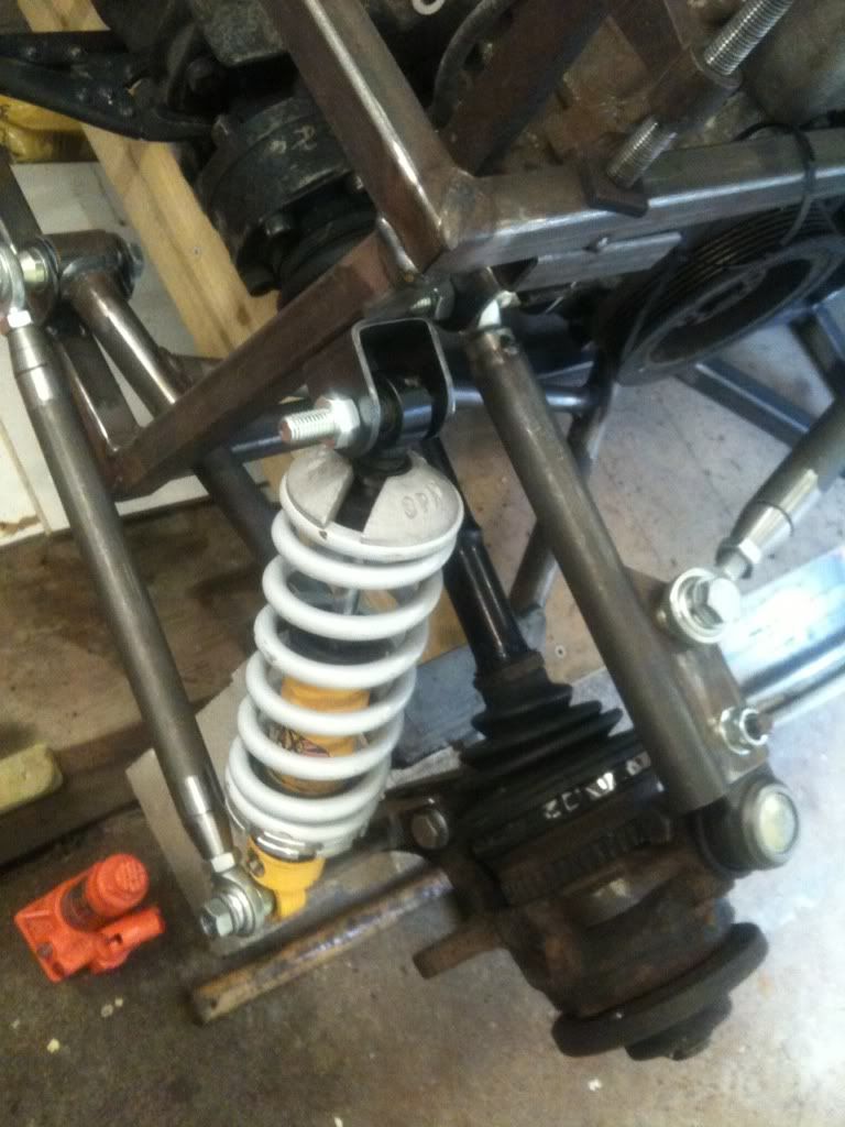
Any comments??
Rob
20vt powered rear engined locost
|
|
|
RIE
|
| posted on 23/2/13 at 03:25 PM |
|
|
quote:
Originally posted by b14wrc
Hi,
Thanks for most of the comments guys.
Last night I made up my brackets to hold the hub:
quote:
Originally posted by Doug68
First to say I'm not an engineer and I have zero welding skills, so this may be a daft question(s): your brackets seem to bolt to the upright
with no bar travelling through it, unlike the bolt in the Sylva setup - is that the case? If so, the welds are carrying the full force, right? Will
they be strong enough?
[Edited on 23/2/13 by RIE]
|
|
|
b14wrc
|
| posted on 23/2/13 at 04:09 PM |
|
|
There is a 120mm long bolt going through the whole lot mate.
Plus inside that 20mm tube there is a ss sleeve. The load is not solely on those welds no.
Rob
20vt powered rear engined locost
|
|
|
phelpsa
|
| posted on 23/2/13 at 05:04 PM |
|
|
quote:
Originally posted by b14wrc
Hi all,
I am thinking about arranging my shock something like this:
Any comments??
Rob
That looks like it will work to me Rob, certainly preferable to mounting it on the wishbone.
|
|
|
phil clegg
|
| posted on 1/3/13 at 10:29 PM |
|
|
build
I like the fact you are building something slightly different.This sometimes means help is a bit harder to find and you become a develope engineer for
others.I prefer the non well travelled engine choice and wish you luck in the build...
|
|
|
b14wrc
|
| posted on 2/3/13 at 08:54 AM |
|
|
Thanks Phil.
I havnt done much on the car as I have been busy with my MSc and work, but I have a week off at Easter and I'm hoping to get this rear
suspension finished completely.
I will update in a few weeks.
Rob
20vt powered rear engined locost
|
|
|
b14wrc
|
| posted on 4/4/13 at 12:01 PM |
|
|
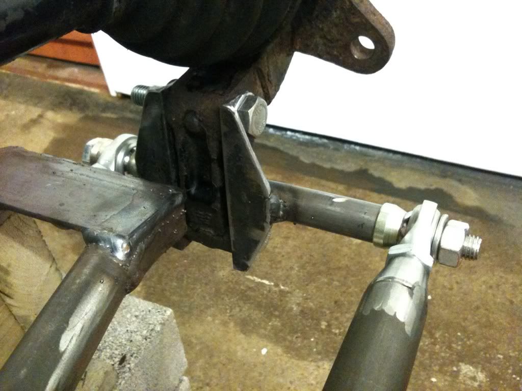
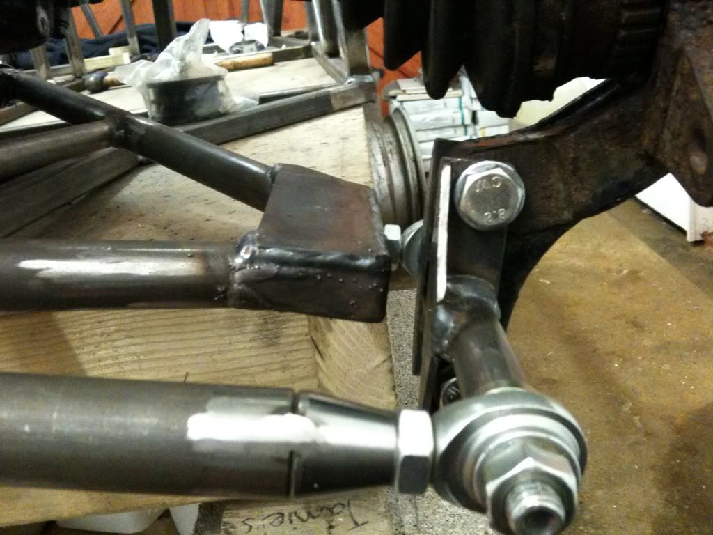
Hi all,
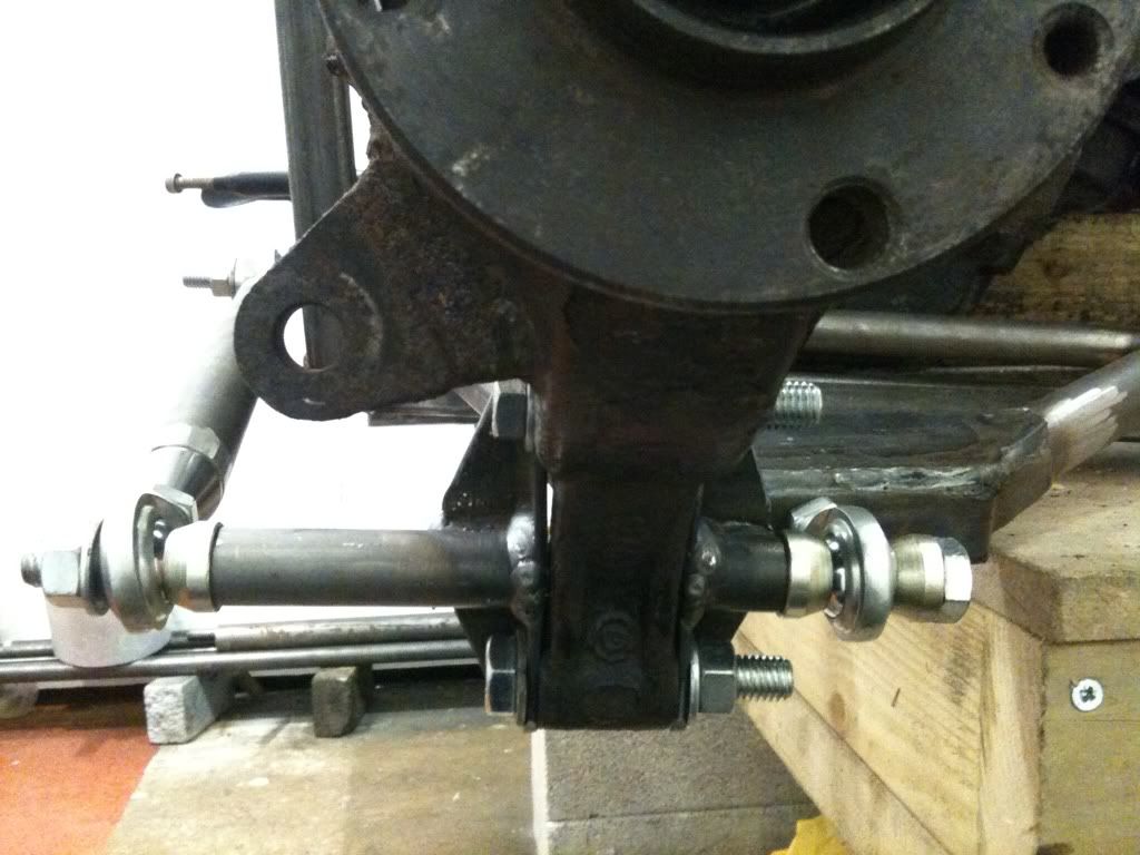
Well I had a bad day on Tuesday with the car, nothing seemed to work and progress was slow. Wednesday afternoon completely the opposite. Very pleased
with the final (not 100% welded and there are bushes to make!) design, it seems to work better than before and I now don't have the loading
going through that rose joint every one was concerned with.
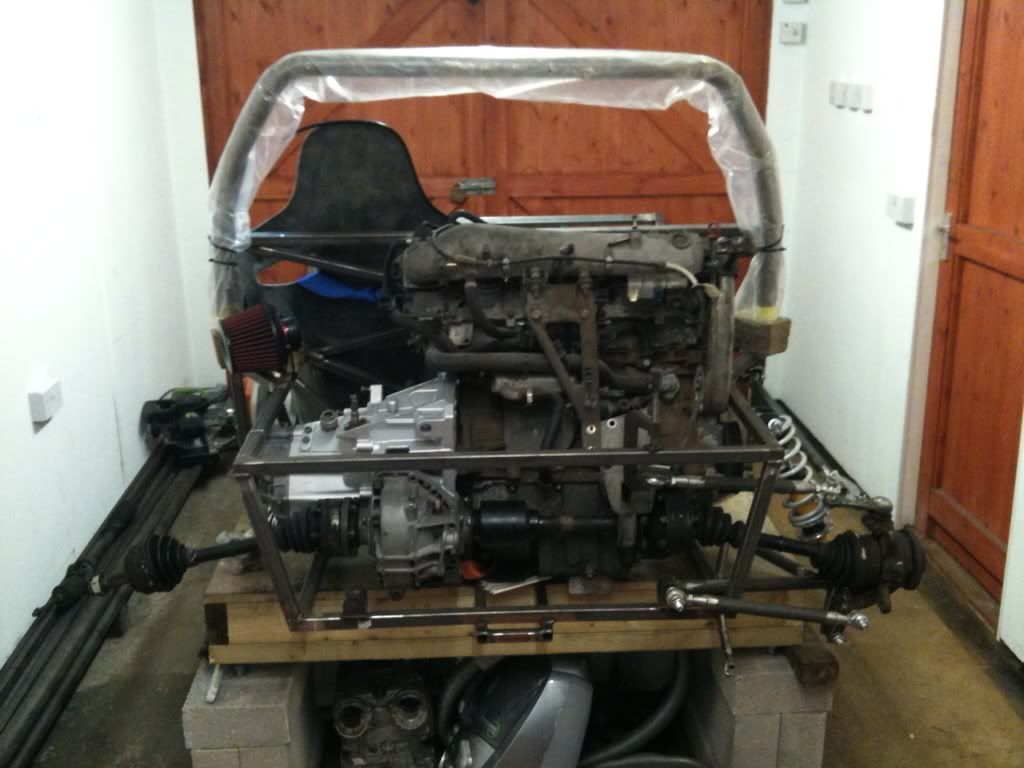
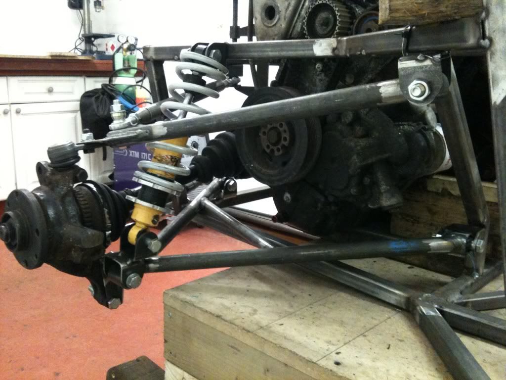
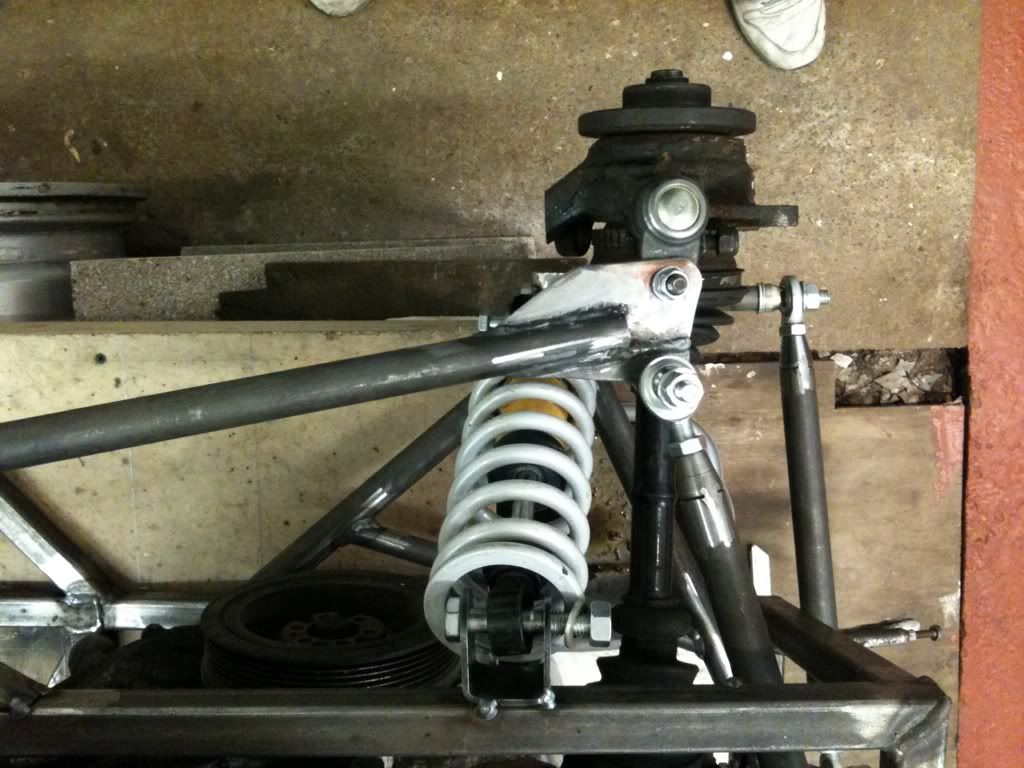
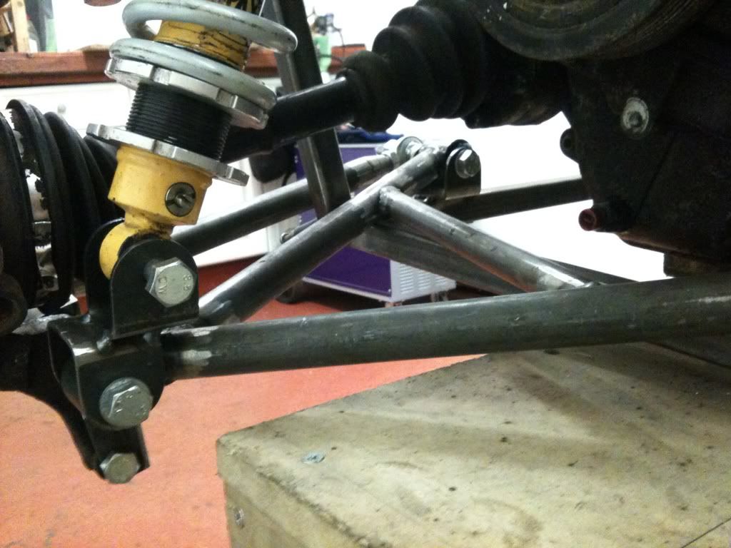
The shock had to go infront of the drive shaft and you will see it isn't mounted directly to the bone. Also, the bottom arm is now a triangle as
suggested.
Any comments??
Rob
20vt powered rear engined locost
|
|
|
MikeRJ
|
| posted on 4/4/13 at 02:08 PM |
|
|
Sorry if I'm being thick, but what stops the double 'U' bracket assembly from just flipping over? Is it welded to something on the
other side?
|
|
|
b14wrc
|
| posted on 4/4/13 at 03:15 PM |
|
|
Do you mean the plate the ball joint bolts too??
If so, the trailing arm is a PU bush so won't slow the ball joint to flip over.... Is that what you mean? Good point though and I had thought
it. But should be ok....... I hope.
20vt powered rear engined locost
|
|
|
b14wrc
|
| posted on 4/4/13 at 03:16 PM |
|
|
Lol. See what your saying now. That's welded to a peice which bolts to the up right, it can't move no.
20vt powered rear engined locost
|
|
|
britishtrident
|
| posted on 6/4/13 at 09:33 PM |
|
|
Top arm is all wrong, a wishbone can be made up of two links but the second link has to connect so as two intersect at a point on the
imaginary line joining the ball joints on the first link, otherwise it is going to flop about if any compression force is put on the wishbone.
Using a bush at one end will make no difference.
[I] What use our work, Bennet, if we cannot care for those we love? .
― From BBC TV/Amazon's Ripper Street.
[/I]
|
|
|
mark chandler
|
| posted on 6/4/13 at 10:08 PM |
|
|
Your wishbone mounting on the frame are not parallel with the centre line of the chassis, the top rear bracket to is closer to the centre line than
the front top, the bottom rears look to be an inverse of this so I suspect you will get rear wheel steering. It was far better the way you had it
earlier on in this thread.
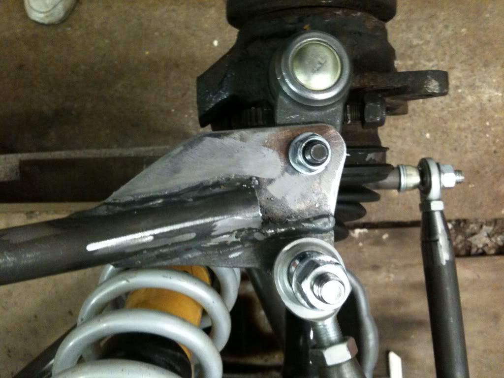
I assume the top ball joint bracket extends to the second bolt, however as BT has stated you really want the ball joint to be the intersection of the
wishbones. Have you done it this way to ensure that when a wheel is fitted it does not foul the inner rim? If you have not dropped a wheel on this
assembly I suggest you do quickly as bones get in the way!
Although you have put a lot of effort into this I would suggest a redesign is called for before you go any further
[Edited on 6/4/13 by mark chandler]
[Edited on 6/4/13 by mark chandler]
|
|
|