Two questions...
1. How important is adjustment at the rear?
2. What's the best way to achieve this?
Here's my current design....
(Green circled bits are staying, red circled bits need changing... Possibly)


Any feedback is welcome!
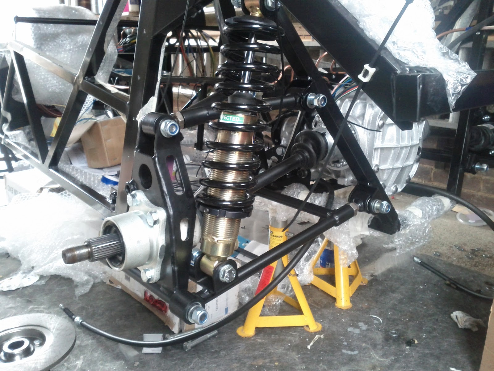
Ok, so I'm about to start cutting steel for my rear wishbones and i realise I only have camber adjustment on the rear!
Two questions...
1. How important is adjustment at the rear?
2. What's the best way to achieve this?
Here's my current design....
(Green circled bits are staying, red circled bits need changing... Possibly)
Any feedback is welcome!
Being able to adjust rear toe is handy. It's difficult to build it with tight enough tolerance to set it without adjustment.
I have it on mine via a cammed bolt on the inner lower wishbone (similar to how MX5 wishbones adjust though my bolt is from a Ford). It adjusts enough
to give me a tad of toe in. Alternatively a rose joint on the upright would do it.
That's exactly what I was thinking, I know I'd be annoyed when I took it for alignment and they told me one side was 1mm out haha! Have people done similar mods on their cars? I'm thinking of changing all 3 outer links with rose joints!?
Ah, you found the diff.
Here a JBA Falcon IRS with a rosejoint for toe adjustment
http://youtu.be/cRD1jIoBkE4?list=PLOD18N_fBFiNJuXU5HSJY4j4flVYUuXJ1
I would add some more mounting point on the upper suspension mount on the chassis (like the coilovers) so you can optimize the geometry for the
specific application.
How is your IRS assy mounted to the ladder frame?
[Edited on 17/9/14 by ettore bugatti]
I put rose jointed rear lower wishbones on my roadster. It allowed boss racing to setup the car perfectly to fractions of a mm
The old fashioned method was to shim the hub mounting.
Washers if way out, generally thin (a few thou) strips of brass or tin.
Adrian
My Robin Hood uses the full Sierra rear end so the only option ( until I replace with Haynes set up) is camber wedges
I bought these off here a while back
Oval racer boys use washers under the hubs on Sierra and Granada
I'm doing what Ash did, but gonna rosejoint all the joints top and bottom. I didn't put the rear wishbone brackets on my chassis so I don't know how accurately installed they are. It's a pain to get the wishbones in so I'm assuming not very accurately aligned.
I don't really fancy shimming, plus it's not necessary considering I can change the design to avoid it!
I've already changed the design of the rear upright once (now a 5mm laser cut and bent plate using 106gti calipers) so another change is no
problem!
quote:
Originally posted by ashg
I put rose jointed rear lower wishbones on my roadster. It allowed boss racing to setup the car perfectly to fractions of a mm
quote:
Originally posted by ettore bugatti
Ah, you found the diff.
Here a JBA Falcon IRS with a rosejoint for toe adjustment
http://youtu.be/cRD1jIoBkE4?list=PLOD18N_fBFiNJuXU5HSJY4j4flVYUuXJ1
I would add some more mounting point on the upper suspension mount on the chassis (like the coilovers) so you can optimize the geometry for the specific application.
How is your IRS assy mounted to the ladder frame?
[Edited on 17/9/14 by ettore bugatti]
If you can change the design I would make a "Z" wishbone. Basically an A frame from the the forward hub mounting point rose jointed at the hub end, to both chassis points, then a turnbuckle with L/R handed joints from the rear hub mounting point connecting to the A frame just forward of the rear chassis mounting point.
A detail perhaps, but I would mount the antiroll bar droplinks as far outboard as possible.
That way it will be more effective with a light gauge bar.
I've probably come into this a bit late, but both the ARB and coilover mounting seem wrong. With the forces they will apply, having them in the middle of a tube seems like a bad idea? I'm guessing there is a reason why the coilover is mounted mid wishbone rather than on the top of the upright as per the original Haynes design?
quote:
Originally posted by Mr C
If you can change the design I would make a "Z" wishbone. Basically an A frame from the the forward hub mounting point rose jointed at the hub end, to both chassis points, then a turnbuckle with L/R handed joints from the rear hub mounting point connecting to the A frame just forward of the rear chassis mounting point.
quote:
Originally posted by Slimy38
I've probably come into this a bit late, but both the ARB and coilover mounting seem wrong. With the forces they will apply, having them in the middle of a tube seems like a bad idea? I'm guessing there is a reason why the coilover is mounted mid wishbone rather than on the top of the upright as per the original Haynes design?
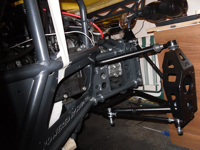
Similar looking wishbones on a IRS striker - showing adjustable mounts. (albeint limited to increments of 0.5 x the thread pitch)

That looks EXACTLY like the design I looked at when doing mine, only difference being that has holes in the side of the upright!? Weight saving?
quote:
Originally posted by Lew The Machine
That looks EXACTLY like the design I looked at when doing mine, only difference being that has holes in the side of the upright!? Weight saving?
quote:
Originally posted by loggyboy
quote:
Originally posted by Lew The Machine
That looks EXACTLY like the design I looked at when doing mine, only difference being that has holes in the side of the upright!? Weight saving?
Standard Raw design, but yes, I would expect that's the reason.

That's actually 2 builds, top one is mine, which has sierra disc hubs and carriers. The 2nd is a chap called Mikes whose using the Golf rear
brake setup that will mount to the 2 extra holes on the upright, that used the sierra drum hub carriers.
The uprights are Raw supplied, so I doubt a CAD file is readily available unless some one has drawn up their own.
Nothing wrong with Shimming it, but its a pain to change once set if you want to change to a different set up.
If you have the time rose joint it.
quote:
Originally posted by Lew The Machine
What do you mean by add some more mounting points? To change the shock angle?
The IRS will have a "male" box section piece both sides which slides inside the "female" ladder chassis.
It will all be braced to the rollcage/spaceframe so it's not going anywhere, the only problem I'm having is torsional stress throughout the length of the chassis, hoping to sort that with more bracing though haha!
 .
. 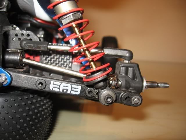
Apologies I missed the JBA post. yes similar.. though I would use a turnbuckle and rose joionts at both ends of the adjustable arm. This will alllow you to adjust the toe by slackening off two lock nuts and rotating the turn buckle, rather than having the dismantle the roase joiny and screw it in or out and resaassemble. I'll try and find an image of what I mean.
Found an image, this is looking towards the back of the car.
quote:
Originally posted by Mr C
Found an image, this is looking towards the back of the car.
quote:
Originally posted by Lew The Machine
Good question about shock position, again it's not confirmed but I've seen it done that way on other rear ends so thought it wouldn't be a problem? The reason for having it low down was to avoid having to fabricate a relatively heavy duty shock mount at a high level, I thought I'd try and utilise the rear wishbone & diff mounting frame for as many purposes as possible!?
Ok so here's my first re-design!
I've left the top joint as a bush but I might change that to a rosejoint too as it don't like the idea of effectively "twisting"
when adjusting toe-in/out!?
I may also change the angle of triangulation to sit behind the rosejoint brackets on the diagonal!
I've moved the shock out and closer to centre, this has forced me to decrease the angle it was sitting at... Not too drastically but still!

[Edited on 19/9/14 by Lew The Machine]
Looking good. The second joint was rose jointed on mine to allow the movement. Makes sense to have the triangulation behind the inboard rose joint,
maybe move the rose joint further inboard making the turnbuckle longer??
Anyhow good job and loving the CAD work.
quote:
Originally posted by Mr C
Looking good. The second joint was rose jointed on mine to allow the movement. Makes sense to have the triangulation behind the inboard rose joint, maybe move the rose joint further inboard making the turnbuckle longer??
Anyhow good job and loving the CAD work.


ok, Bit more work done on the design (pics to follow)...
Do we like these or are they to be avoided?
http://www.mcgillmotorsport.com/m12-turnbuckle-link-adjustment-210mm-240mm-linkage-12mm-559/
And which rose Joint do i want? They will be M12 but there are 3 types...
http://www.mcgillmotorsport.com/metric-rod-ends-accessories-male-rod-ends-metric/
Never played with rose joints so any warnings/advice you have would be appreciated!
Cheers 