
Description

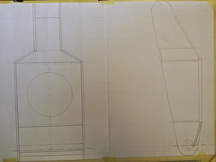
I've been thinking about re-designing the rear uprights for my Haynes Roadster. The book uprights seem unnecessarily complicated and heavy
compared to other designs I have seen. I've drawn up some plans for some uprights which should be a lot easier to make up as well as being
lighter and stronger. The suspension geometry remains the same as the original uprights. I would value your opinions and ideas on these.


Description
Is that a drawing of the existing design or yours? Looks very similar to the Haynes ones. Which look the same as mk ones.
I've seen mk rear uprights bend when used in anger on the track so don't make them too light.
The drawings are mine. The Haynes roadster uprights use a round tube on which all other parts are welded. I'll have a look at some mk uprights to
compare them.
[Edited on 13/10/14 by Derkjohn]
I haven't looked at the rear uprights for a while but from memory the only difference to yours seems to be the tube and your front plate looks
much thinner than the Haynes one. Bear in mind that tubes are generally much stronger than flat pieces of plate and you will need a nice big thick
piece of plate to bolt the hubs into. The rear uprights are actually quite easy to make so I wouldn't worry to much about constructability unless
you plan on making loads of them. Any thoughts on how much weight you think you will save - I wouldn't have thought it would be much.
If you do want to redesign the uprights I would have thought one of the best mods would be to redsign to allow you to get smaller wheels on the
roadster. Being limited to 15" is a pain and I'm sure 13" wheels would be a big benefit.
The MK Indy uprights had a slab of ~10mm thick plate fully welded to the front face of the upright with threaded holes to bolt the Sierra hub to.
Thanks for the input. I forgot to mention that I was planning to weld captive ht nuts behind the 5mm plate instead of tapping the mild steel plate.
The issue with making the uprights is that I don't have access to the pre-cut kits you can get in the UK and also the prospect of making 4x 84mm
holes in the 10mm plates seem a bit much.
bad idea.
i have seen GBS, Luego and MK ones like your design collapse.
if you look at the upright. hold it at the top and the bottom and try and compress it like a coke can. 3mm the sides bow outwards.
the 5 inch circular tube in the roadster upright stops the side walls bowing in or out.
the coke can crushing effect is what happens when you go over a bump and the upright compresses agains the damper/chassis.
of all the designs the GBS one is the worst, the front face and the sides are just one bit of bent 3mm plate.
haynes upright is much stronger. think about bolting the upright to the bench attach the hub and wheel to it then take a 6 foot lever bar to it,
think bent 3mm plate wont bend?

to improve your design fit a tube in the middle then box the back round the tube to support the side walls then upgrade the front plate to 10mm
minimum! anything less will bend i have seen it first hand several times!
the haynes design is actually 10mm plate on the front then the 5inch ring then another 10mm plate for reinforcement welded behind inside the ring!
if you look at the sierra rear arms the plate that everything mounts to is at least 10mm thick!
I'm in the same boat, I'm making mine to a similar design (5mm plate laser cut and press brake bent) but with internal webs to stiffen the
front plate, the haynes design is a bit over the top IMO but I can totally understand how anything less can bend... It's horses for courses
though, I'd rather save 5kg of unsprung weight and risk a bent upright when I clatter the wheel into something than design something JCB would be
proud of!
One thing worth noting is that I've moved my shock mount to the lower wishbone so the upright is loaded in a different manner...
ave you got a water jet cutting service nearby? they should do 10mm plate for you for a reasonable price
I too have designed similar uprights for my project.
combining your idea and the one posted above how about something along these lines?

have spent weeks agonising over upright designs and safety always has to be the most important factor!
Best to try and visualise the loads acting upon the various areas and what's stopping it from bending
You'll find the shock acting off the top of the upright much easier. on mine it's a pushrod off the bar that the bushes (shown crosshatched)
are mounted on, but driveshaft clearance is close
[Edited on 13/10/14 by 43655]
[Edited on 13/10/14 by 43655]
[Edited on 13/10/14 by 43655]
More triangles!
http://2.bp.blogspot.com/_E5ELxVgPQd4/SxS-Eu1ZUNI/AAAAAAAACiI/Gih9CLwdY7U/s1600/tvr_blackpool_tvr-unofficial-blog_9.jpg
And don't forget to have a sneek peak at the Rorty IRS plans.
and more links:
http://www.gt40s.com/forum/gt40-tech-powertrain-transaxles/34994-rear-uprights-fabrication-plans.html