
Plenty of user's on here will be able to advise if it's good/strong enough.
Hi all,
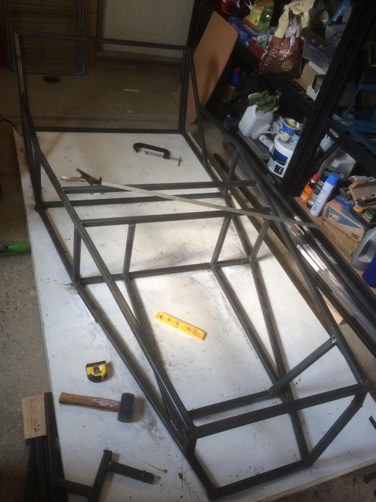
Am new to the forum and have joined as I recently started building a haynes roadster. Have got half way through making the chassis, tack welding at
the moment. This is the first time I have welded and have been practicing on loads of off cuts before hand. Seem to have got the hang of it ok and
have tested a few welds which all seem okay.
The thing is that I am contemplating getting the chassis welded up professionally once it's all tacked in place, anyone know a good welder near
Milton Keynes? Or does anyone live near that is willing to lend a hand/check that my welds are up to the required standard?
Any help/advice would be greatly appreciated,
Mark
There is no standard as it is not checked,as you are going to drive it i think getting it welded by a pro is a good idea.A s a mot tester i see lots of welding and i am quite suprised how bad a lot of it is .So do not just think any one with a mig can use it.Ask around locally there will be a man that can.Possibly a rollcage for motorsport installer nearby.Good luck
Take some pics of your welding and post them up
Plenty of user's on here will be able to advise if it's good/strong enough.
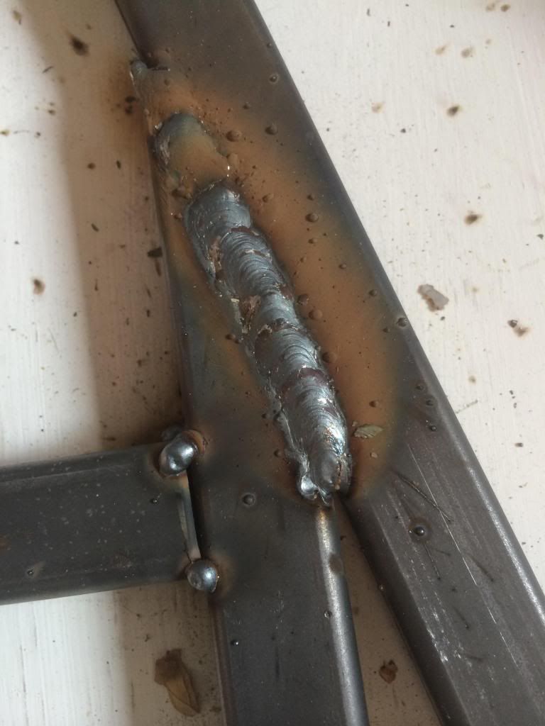
This is an example of one of the welds I have done, where I have done a weld I have then tack welded the other 3 sides to either get a professional to
finish it off or if mine are up to standard then I will go back and complete it once the whole chassis is in place
Your tacks are a bit on the big side. Grind them down then crack on and weld over them. If you can keep that standard up it looks fine.
that doesnt look like it will fall apart. have you cut through a cross section of any of your test welds?
when you tac stuff put the current on the welder right up so its not such a big tac.
I'd be more than happy with that standard of welding, even on a pro built chassis 
Thanks all, I ground a v in it too so it should have penetrated all the way. I will put my current up on the tacks, I was reducing it as I
didn't want such a big tack but then leaving it on longer to ensure it would hold, now thinking about it leaving the power on higher and reducing
the time makes more sense. When I tested my welds I would grind them down then bend them looking to see if there were any weak points. Thanks for the
advice
Looks great to me, when you go around and backfill keep leaping all over the car when finishing keep your welds short and do not do all sides at once
or the heat will distort the frame.
I,ve seen professional welds that do not touch yours.
Weld shape from the photo looks quite OK. I've been supplied 'professionally welded' components that look far worse.
If your MIG has a burn back adjustment, might be worth playing with a slightly longer duration to assist the shallowing at the end of the weld (or
just spark it up again at the end of the run).
quote:
Originally posted by phil clegg
There is no standard as it is not checked,as you are going to drive it i think getting it welded by a pro is a good idea.A s a mot tester i see lots of welding and i am quite suprised how bad a lot of it is .So do not just think any one with a mig can use it.Ask around locally there will be a man that can.Possibly a rollcage for motorsport installer nearby.Good luck

quote:
Originally posted by motorcycle_mayhem
Weld shape from the photo looks quite OK. I've been supplied 'professionally welded' components that look far worse.
If your MIG has a burn back adjustment, might be worth playing with a slightly longer duration to assist the shallowing at the end of the weld (or just spark it up again at the end of the run).
Rather than turning the voltage (its the voltage that increases by the welder settings) up for tacking, instead I'd turn the wire speed down a
little.
The voltage/current characteristics with a slower wire speed will mean a longer arc length, resulting in higher current (for the same voltage), deeper
penetration, and less filler.
Looks good though!
What you can do, at the end of a run, is to come back along the weld for a few mm This will finish it off nicely.
Thanks again all, am next working on it this Friday so I will give these ideas ago, thank you
I started as a complete novice welder when I started my chassis. I really enjoyed the process of learning to weld, although there were moments when I
felt like throwing stuff out of the window! You will find that some days everything will go like clockwork, and other days absolutely nothing will go
properly - on those days you just have to walk away and do something else before you do some major harm (in fact, I strongly recommend it). What I
found useful was to watch a professional welder do his job, and to pick up tips as I went along - how to hold the torch, what speed to move it along
the weld line, and so on. Most of this I got from a couple of 1-day courses in welding at a local agricultural college.
When I cut all the tubes for my chassis I had lots of odd ends left over. I spent quite a few hours welding these together, grinding them in two
across the welds to check for penetration, and finally beating welded joints senseless with a 2lb hammer to see how easily they came apart. Once I
was reasonably sure that I could make a weld with decent penetration and good strength then I made a start on the chassis.
You should be prepared to grind away any weld that you are unsure about, or that looks second-rate, and re-weld. You should also be prepared to
replace any lengths of tube that you have messed up while grinding away bad welds, or that have been compromised in some way while welding. I reckon
that I must have ground away and re-welded quite a number of joints in my chassis, and replaced 3 or 4 tubes that I was just not happy about when
I'd finished.
It's a great feeling when you finish though! Being able to say "that started as a pile of tubing on the garage floor" does wonders for
your self-esteem.
Progress so far:
I have been tack welding loads to practice then continued tack welding the chassis and am getting the hang of it. I have played about with the
settings but in the end just went for the standard one recommended in the mig welder manual. I have found if I get a lot closer to where I'm
welding and make sure I have excellent lighting and good view of exactly where I'm aiming then a short burst in the middle of the groove I make
on the edges it seems to do the job. Now I am getting more comfortable I realise I don't need to drown the area on loads of molten metal to get a
good tack! So my tacks are getting significantly smaller
[Edited on 27/3/14 by MBrown]
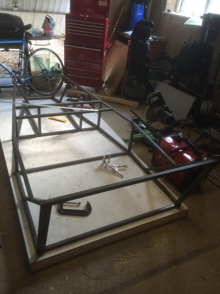
Another progress pic:
I have also now added the rear suspension brackets, fully cut out the middle piece of box section in the front of the gearbox tunnel and added a
number of the chassis plates.
I have altered the back slightly so I can put a larger fuel tank in.
It's soooooo nice to read a thread where obviously a bit of time and care has been taken
to produce a quality result.
Well done mate.
Paul G
Thanks, it's really starting to come together and feel like I have actually made something! Seats have been ordered so I can measure out and weld in some mounting points for the seats. Altering the sump at the mo and waiting for a clutch kit and new gaskets to arrive before I try the engine in place and make up the engine mounts. Will add more pics soon!
Progress update:
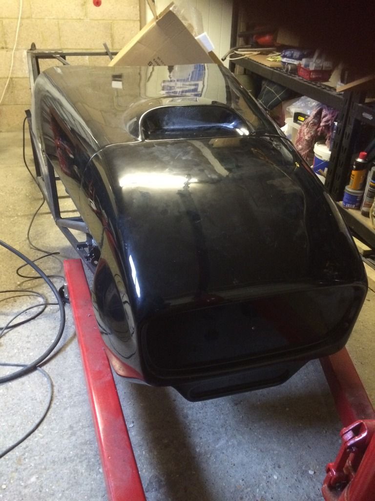
I have bought a full set of fibreglass body panels from Equinox in Faverhsam, the quality is amazing, very pleased. Gone for black with the small
bonnet scoop, I have got the boot space as well as I wanted this car to be relatively practical and usable. I also got the wide nose cone with oil
cooler duct just for looks really.
Equinox

The sump was altered by Rye Guard services Leighton Buzzard, they did a great job and I'd definately recommend them for any metal work.
Rye Guard Services
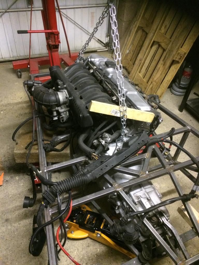
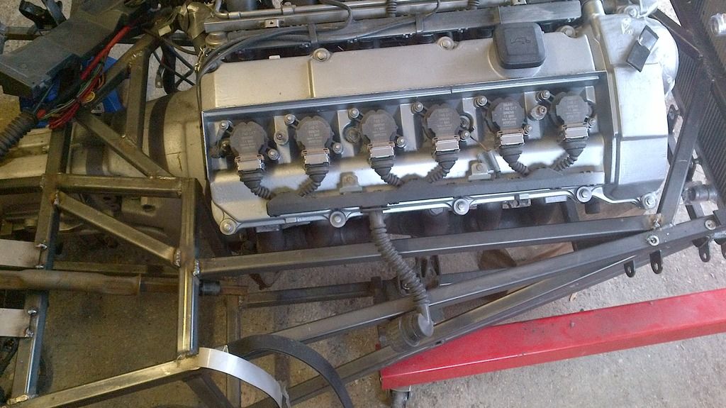
I now have the engine roughly in place and will be making up some engine and gearbox mounts.
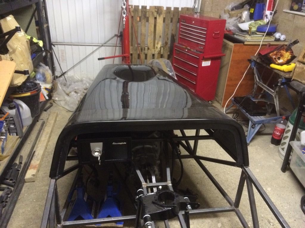
Today I have also bought a safe which will form the glovebox (again as I wanted the car to be practical and useful) so I will be welding mounting
points and nuts on so the safe can only be removed when the safe is open (unless someone wants to cut through several pieces of metal on the chassis
to remove it) and the safe will go just above the passenger footwell and the dash will have an opening which will then reveal the safe. The capacity
of the safe is 9.9 litres so bigger than most normal car glove boxes. The Equinox Scuttle doesn't have a back to it so I will be making one that
accommodates the back of the safe although it won't need much accommodating as the size is almost a prefect fit..
If anyone thinks of any other useful ideas to make the car as usable as possible please let me know
Mainly I'll be looking to use it as a run around and long weekend holiday car. Thanks all
[Edited on 24/11/14 by MBrown]
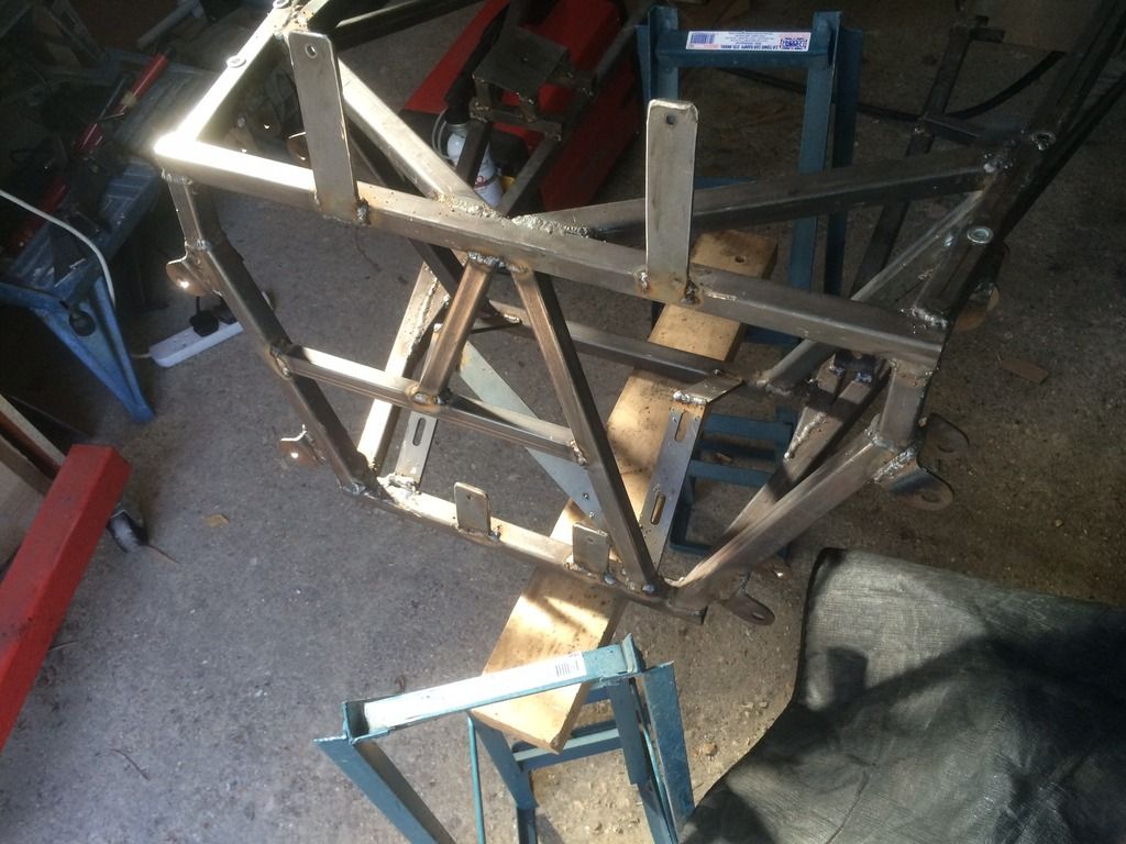
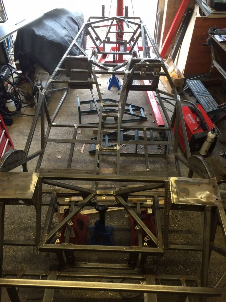
Its been over 8 months since I updated this, so thought it was about time I show the progress on the chassis - I probably should have finished it now
but hey, getting close.
Photo of the body work trial fitting to ensure the engine was at the right height.
Another body work shot with the glove box mounted in place
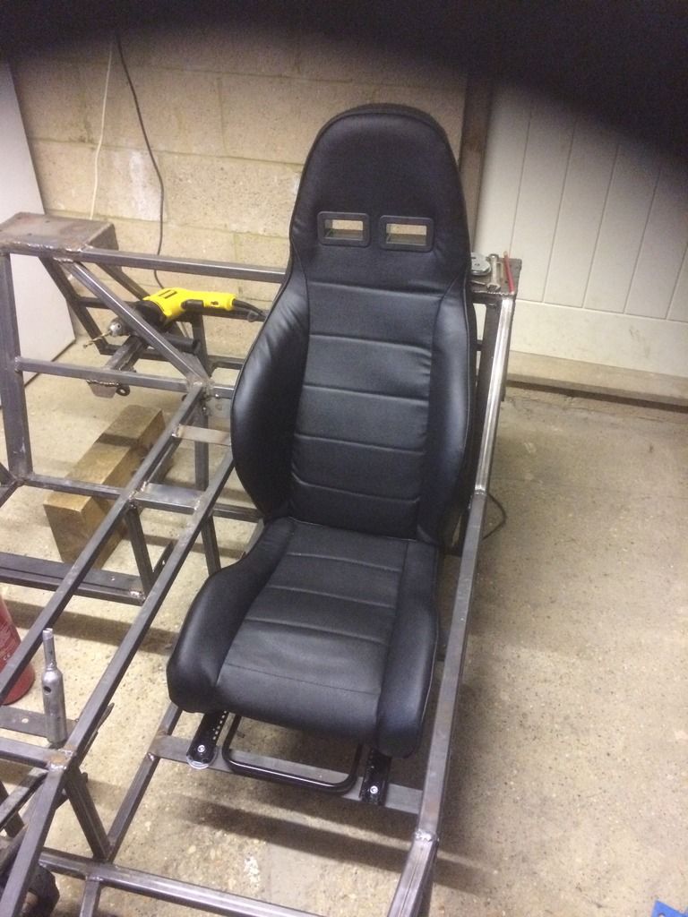
Basic seat mounted in place - hopefully this should be more comfortable for travelling greater distances which I hope to do. I had added some
additional tubing to strengthen this since I took this pic.
I had to amend the Haynes Roadster engine bracing slightly, I have done similar on the other side of the engine.
I have now welded in the footwells, this pic doesn't quite show them fully welded, and I have also now added small cut outs to fill any unwanted
gaps.
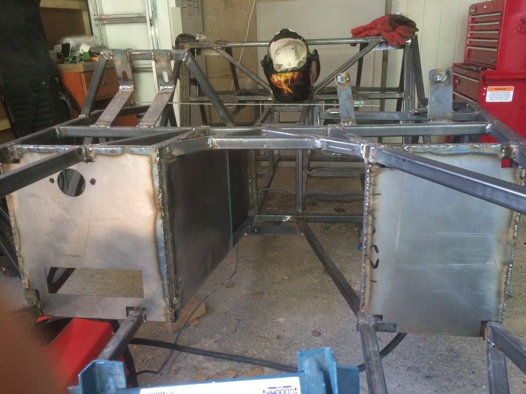
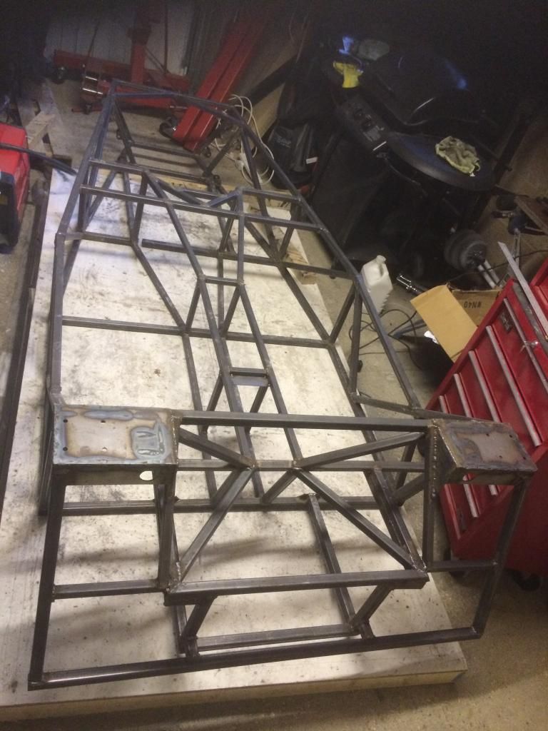
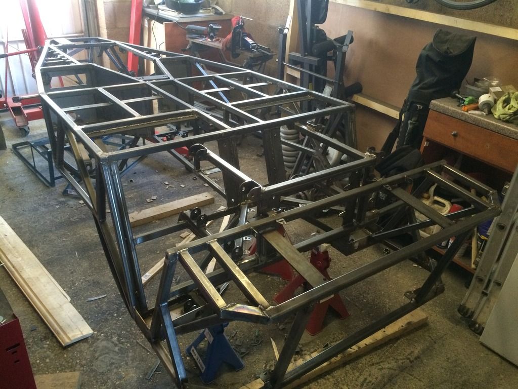
I have then created the rear section of the car. I used 1" box section instead of circular tubing as I want to add a solid roof that will fix to
this easier and although it will be heavier it will be a lot stronger to support it. It will also then fit the equinox bodywork better. I have also
adapted the rear slightly from the plans so it can accept a bigger fuel tank - again something I wanted as I am intending this as more of a GT than a
racer.
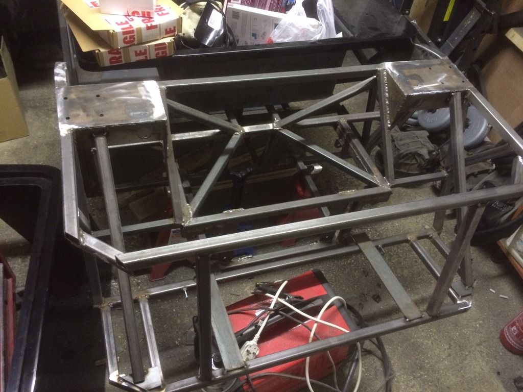
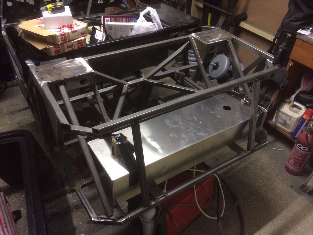
Tank is 30cm longer so will be approx 9-10 gallons and has a small swirl pot underneath to compensate for the greater potential for fuel starvation
around corners. I have only just received the fuel tank so have waited to fully weld the rear in case there are any clearance issues getting it in -
it was close but went in fine in the end.
I also went to add the usual V at the front for extra strength, then realised that my radiator outlet would have got in the way so then adapted it. It
might not be as strong as a V but I thought it was better than nothing. Steering rack support now also on.
The boot will be something like this, I also have a boot lid in fibreglass. Is still need to alter it slightly so it fits flush but I'll do that
when fitting the bodywork once finally assembling it.
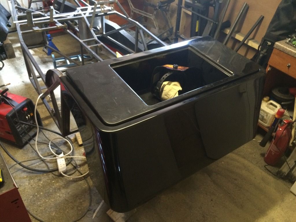
Another shot of the bodywork
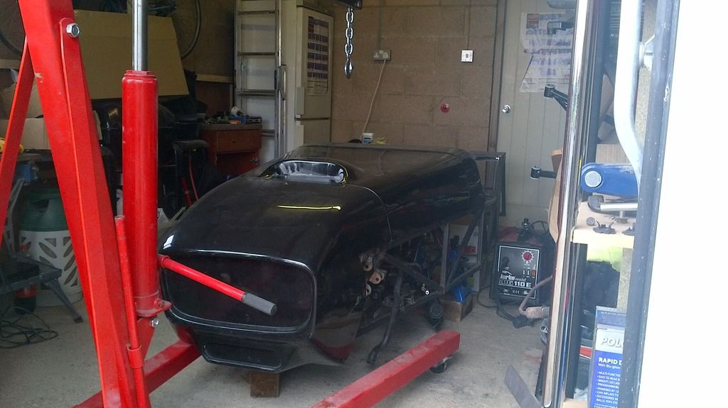
Will post more soon! (hopefully)
Looking good 
Soooo similar to my build, race ya?
I'm interested by the extra brace you've added alongside the cyl head. I've just put a strengthening web on that side and doubled up on
the other side (not ideal). I'm concerned about space on the cyl head side as I'm just trying to plan where the exhaust manifolds route.
I'm looking at turning the rear manifold upside down, modifying it and presenting the outlet just over the top rail and out of the side of the
bonnet. The front manifold, I was thinking of turning the outlet 90deg and poking it out of the side panel. Then hoping to join them in a 2-1 Y piece
or possibly run 2 x motorbike silencers in a shotgun stylee.
I'd be interested to see your sump. I chopped about 25mm out of the base of mine but have added some capacity at the front. It's away
getting welded at the moment but will post pics once done. Overall I've lost some oil capacity but I hope to compensate for this by fitting a big
oil cooler (possibly 30 row) to get a bit of capacity back and also keep cool what I've got.
http://locostbuilders.co.uk/viewthread.php?tid=198679
[Edited on 2/8/15 by Nickp]
You're already ahead! I am hoping to finish the welding off, give it a few coats of paint and maybe start putting the floor on in the next couple
of weeks. I haven't taken any off the bottom of the sump yet, just off the side. Did you have to shorten the oil pickup? Another builder on here
hasn't taken any off the bottom so I might just see what I think when it is on wheels and the ride height sorted - we shall see.
For the exhaust manifold, I have seen this and might give it a try:
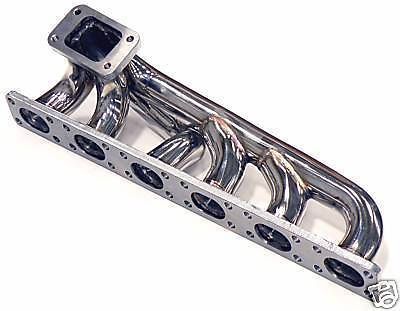
It should give more space near the pedal box but until I get a pedal box in and buy the exhaust I won't know if it's enough. I probably
won't get those until after the new year but I'll let you know how it goes
Well I got the engine as far back as it'd go and low enough to clear the Equinox bodywork by a few mms. In that positionI had the sump about 75mm
below the chassis!! So in my opinion it definitely needs chopping, unfortunately.
I've seen those manifolds too but I'm going to try with the std ones first in true Locost fashion.
I'll watch your results then before I get a new manifold and will have another look at the sump when it's back in, and it might be best to
eventually set it up with a dry sump system
[Edited on 2/8/15 by MBrown]
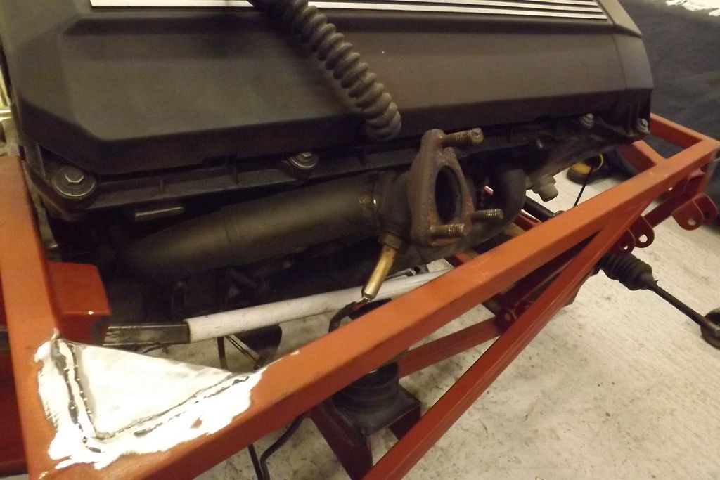
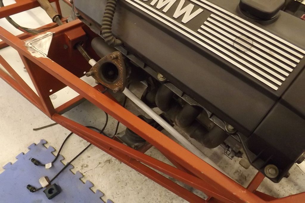
I've just had a go at the rear manifold. Chopped the outlet and lambda sensor off. Spun it round to clear the head and get a better angle to poke
it out of the side of the bonnet. I intend to poke the front one out just below this one before joining them up.


Here's my finished sump-

Have you seen the price of an M52 dry sump kit?? Deffo not locost!! 
Oh, I might have a problem with doing that with the exhaust manifold due to my bracing in the engine bay......
[Edited on 4/8/15 by MBrown]
quote:
Originally posted by MBrown
Oh, I might have a problem with doing that with the exhaust manifold due to my bracing in the engine bay...... 😕
Today I have spent what seems like forever welding on 100 brackets! I decided I didn't want to drill the chassis repeatedly to then rivet the
fuel, brake lines and electrics so I managed to find these which were 100 for �40. They also have the added benefit of keeping the chassis sealed,
which hopefully should make it last longer without rusting slowly inside. This also means that when i bolt P clips to them, I can change, replace or
repair any fuel lines etc without the need to drill rivets and therefore not leaving any bits of rivet rattling around in the chassis. I spaced them
out every 10cm, and 100 seemed to be enough to cover every possible route for electrics, fuel lines and brake lines.

[Edited on 4/8/15 by MBrown]
Chassis finally finished! Thanks all for the advice and guidance!
Nice idea, and I understand your concern around rattling rivets!! I guess with a BMW engine you're not overly worried about minimising weight, so
a few extra brackets won't make much difference.
Where did you get them from?
I got them here:
ebay brackets
Definitely easier than drilling many many holes..... and as you pointed out I have a relatively heavy engine so I wasn't too worried about adding
the extra weight. I also used slightly thicker metal for my chassis so it is approx 25kg heavier than the usual but it is a lot stronger.
I did a similar thing on mine but used washers bent at 90 and tacked the corners to the chassis.
quote:
Originally posted by ceebmoj
I did a similar thing on mine but used washers bent at 90 and tacked the corners to the chassis.
I tried the washers idea but the heat from welding left them too easy to break off, I could've got some heavier duty washers but then saw those brackets
quote:
Originally posted by MBrown
I tried the washers idea but the heat from welding left them too easy to break off, I could've got some heavier duty washers but then saw those brackets
I managed to find some mild steel washers relatively cheaply, that then avoids poisoning and saves the time of making something:
http://m.ebay.co.uk/itm/M5-Mild-Steel-Washers-14-5mm-O-D-X-5-4mm-I-D-X-1-4mm-Thk-/141718028183?nav=SEARCH
The above washers are quite small, the same person did have an auction with some that were 19 mm OD, so message him if you do want a bigger size, the
19mm OD didn't cost much more.
with my brackets I have bought some short bolts so will bolt lines in place- again may add a small amount of weight but makes it so easy to repair or
alter later on.
Hope that helps
[Edited on 7/8/15 by MBrown]
[Edited on 7/8/15 by MBrown]
Hi there, sorry for the stupid question but your chassis a standart o 442?
Hi, it is the standard Haynes Roadster chassis from the Haynes Roadster book completed by Chris Gibbs
quote:
Originally posted by Nickp
I've just had a go at the rear manifold. Chopped the outlet and lambda sensor off. Spun it round to clear the head and get a better angle to poke it out of the side of the bonnet. I intend to poke the front one out just below this one before joining them up.
Mark,
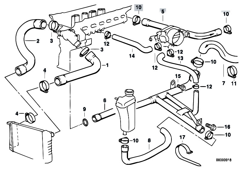
Wonder if you can help, I'm confused by the cooling ststem on these engines, appears to be two circuits, cylinder block fed from the water pump
and a second circuit through the cylinder head. Do you know how this setup will be plumbed in with a radiator and expansion tank?
I found this diagram but cannot make sense of it...
 post img
Craig :-)
Hi Craig,
I haven't yet plumbed mine in so I don't know exactly, I did work it out from the manual several months ago but would have to have another
look. From a quick google I think this is a slightly better picture. Most of the connections should remain exactly the same. The only one that you
would have to change is the one on the upper right hand side of the picture. The two pipes going away from the engine on the upper right hand side go
to the heater in the car and return from it, so if you don't use a heater then these two can just be connected together. I will be using a heater
so my connections should be exactly the same. There are a couple of other people who have completed their builds with this engine - Steve Wallace
being one and he has been incredibly helpful.
Hope this helps,
Mark
quote:
Originally posted by MBrown
Hi Craig,
I haven't yet plumbed mine in so I don't know exactly, I did work it out from the manual several months ago but would have to have another look. From a quick google I think this is a slightly better picture. Most of the connections should remain exactly the same. The only one that you would have to change is the one on the upper right hand side of the picture. The two pipes going away from the engine on the upper right hand side go to the heater in the car and return from it, so if you don't use a heater then these two can just be connected together. I will be using a heater so my connections should be exactly the same. There are a couple of other people who have completed their builds with this engine - Steve Wallace being one and he has been incredibly helpful.
Hope this helps,
Mark