givemethebighammer
|
| posted on 19/4/04 at 06:36 PM |

|
|
Dash question 1
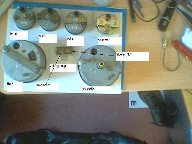
Please see attached picture of back of my smiths gauges (from Triumph Dolomite)
I am trying to work out how the voltage regulator is connected in (suspect it just regulates the voltage to the lighting bulbs, but not certain).
thanks
Rescued attachment gauges.JPG
|
|
|
|
|
stephen_gusterson
|
| posted on 19/4/04 at 06:45 PM |
|
|
on older cars the voltage regulator supplies the positive power to the dials, its NOT for the lamps.
If you hav eany doubts of how to connect it, id suggest getting hold, of a haynes manual for the donor dials or contact an enthusiast web site.
atb
steve
|
|
|
givemethebighammer
|
| posted on 19/4/04 at 06:55 PM |
|
|
hmmm, gets stranger. Speedy cables who supplied the regulator said it would run up to 3 gauges, hence my thoughts on the lighting bulbs. The regulator
has 2 input terminals (common connection) and 2 output terminals (common connection). Can't see how I can wire the fuel sender, temp sender and
the fuel sender through one regulator ?
|
|
|
NS Dev
|
| posted on 19/4/04 at 07:02 PM |
|
|
Unless I am being stupid (which is entirely possible remember!) you just wire them in parallel from the VR outputs, so giving a nice 12v to each one.
If the 2 outputs of the VR are common then it doesn't matter which one, or if you use both etc, are the 2 just for convenience of connection?
|
|
|
NS Dev
|
| posted on 19/4/04 at 07:03 PM |
|
|
only just spotted, mr bighammer, that you are only just up the road in Loughborough! I am in Hinckley near leicester, if you need any help etc.
|
|
|
givemethebighammer
|
| posted on 19/4/04 at 07:07 PM |
|
|
quote:
Originally posted by NS Dev
Unless I am being stupid (which is entirely possible remember!) you just wire them in parallel from the VR outputs, so giving a nice 12v to each one.
If the 2 outputs of the VR are common then it doesn't matter which one, or if you use both etc, are the 2 just for convenience of connection?
I am being stupid NS Dev any chance of a diagram (durr I can relate to pictures much better). Thanks for the offer may well pop up to see you if this
wiring lark gets too hairy !!!

[Edited on 19/4/04 by givemethebighammer]
|
|
|
NS Dev
|
| posted on 19/4/04 at 07:46 PM |
|
|
I may be bing completely stupid here so bear with me (I never bothered with a regulator before but it does make the guages more accurate!), but you
said that the voltage regulator (vr) had 4 pins, in two pairs, each pair being joined so was at common voltage. 1 pair was input, 1 pair output. is
this right?
If so, just connect all the positive supply sides of all the guages to the output of the regulator and it should work.
|
|
|
NS Dev
|
| posted on 19/4/04 at 07:48 PM |
|
|
just read your post again, are you getting at the fact that there are not enough connections on the regulator for all the guages? If so, just put
several of the supply wires into one crimp spade to plug onto the regulator.
|
|
|
TPG
|
| posted on 19/4/04 at 08:16 PM |
|
|
Regulators in dash wiring used to supply the 12v nice and smooth to the gauges.So the needles don't swing about etc.Most gauges work on +12v
feed and the earth or negative is varied back by the relevent sender unit.I.e the temp' sender sends back -0 to -12v's.
..Which was nice..
|
|
|
givemethebighammer
|
| posted on 19/4/04 at 09:09 PM |
|
|
aha, I think the penny has dropped.
The fuel gauge, temp gauge and volt gauge all have 2 terminals on the back of them. I am right in thinking that the earth is through the case via the
screw in the centre of the gauge, one terminal is the battery feed and the other is the sender connection ? If this is right the it starts to make
sense. However do I need to regulate the volt gauge - logic says not or it wouldn't read correctly !!
|
|
|
stephen_gusterson
|
| posted on 19/4/04 at 09:40 PM |
|
|
the case is always the earth - so you are on the right track!
atb
steve
|
|
|
chrisg
|
| posted on 19/4/04 at 09:58 PM |
|
|
The regulator puts out 9 v not 12 and it'll supply three instruments from the "I" (for instrument)contact.
Cheers
Chris
Note to all: I really don't know when to leave well alone. I tried to get clever with the mods, then when they gave me a lifeline to see the
error of my ways, I tried to incite more trouble via u2u. So now I'm banned, never to return again. They should have done it years ago!
|
|
|
NS Dev
|
| posted on 19/4/04 at 11:33 PM |
|
|
9v??? Now I'm confused!! How come my guages read correct (although bumpily) with unregulated 12v then (although they are aftermarket ones not
triumph ones)
mr bighammer, you are quite right about the guage connections, didn't realise that the question was about them, thought it was more the
regulator!
Cheers,
Nat
|
|
|
GO
|
| posted on 20/4/04 at 05:14 PM |
|
|
for the gauges, it is not:
case is earth
one feed is from sender
second is for illumination??
|
|
|
chrisg
|
| posted on 20/4/04 at 06:47 PM |
|
|
quote:
Originally posted by NS Dev
9v??? Now I'm confused!! How come my guages read correct (although bumpily) with unregulated 12v then (although they are aftermarket ones not
triumph ones)
Think you've answered your own question there mate.
Triumph guages run off 9 volts.
Cheers
Chris
Note to all: I really don't know when to leave well alone. I tried to get clever with the mods, then when they gave me a lifeline to see the
error of my ways, I tried to incite more trouble via u2u. So now I'm banned, never to return again. They should have done it years ago!
|
|
|
givemethebighammer
|
| posted on 20/4/04 at 09:01 PM |
|
|
quote:
Originally posted by GO
for the gauges, it is not:
case is earth
one feed is from sender
second is for illumination??
illumination is via a separate bulb holder with its own live feed, earthed through the instrument case
|
|
|
britishtrident
|
| posted on 21/4/04 at 04:28 PM |
|
|
The gauges get I think an 11 volt supply from the regulator excuse the hazy memory but it is years since worked on one of this type.
The "B" (battery !) terminnal will get battery voltage from the ignition accesory fuse.
The gauges get a common regulated 11v supply off the I (for instruments !) which then goes through each gauge to the transmitter/transducer/sender to
earth I also know the case of the regulator must be earthed.
The lighting is suplied with battery voltage from the side light connection via the dashlight switch (if fitted). For the lighting to work the case
of each instrument must of course be earthed.
For reilabilty and simplicity apart from the amps and volts I have just mechanical auxilary instuments on my car --- combined oil and water gauge
from an MG no fuel gauge.
[Edited on 21/4/04 by britishtrident]
|
|
|
NS Dev
|
| posted on 21/4/04 at 11:10 PM |
|
|
mr Bighammer!! The invite for assistance stands if you need it, let me know!
I am going the totally minimalist route. Now I've started competing I realise how little I look at guages anyway. When you think about it, you
only look at the little needle to say to yourself, ok, or not ok!!
I have lights to do this for me. light if water temp goes too high, light if oil press goes too low (less than 35psi), sequential shift light for revs
(what the hell do you use a revcounter for????thought about that one the other day, I used to go round saying you need to know when to change gear,
then realised I did a whole race without looking at it!!!), alternator light and that's about it other than speedo and the indicator/brake/main
beam etc.
|
|
|
SeaBass
|
| posted on 22/4/04 at 07:52 AM |
|
|
British Trident is correct. The regulator actually switches the 12v supply on and off about ten times a second. This gives an average voltage of ~10v.
The gauges then use this voltage to give a reading. They are not affected by the switching because they are bimetallic type. This is why they take
time to get up to speed when ignition is switched on.
As I've said before if you wire the panel illumination into the voltage reg they will flash!!
Smiths theory was that the gauges wouldn't react to swings in vehicle voltage when lights were on etc.
Cheers
|
|
|