
Mick's MNR Mazda: Build Log
micksalt - 16/6/15 at 07:32 PM
Firstly, thank you to all of you for your advice so far, I've finally made a start on this project, the plan being to strip the donor over July,
recondition some parts over August and then things will go a little quiet until I pick up the kit sometime in November, just as soon as I get back
from my honeymoon.
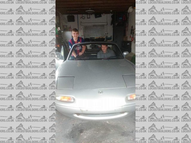
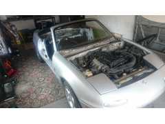
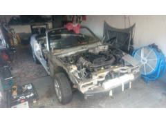
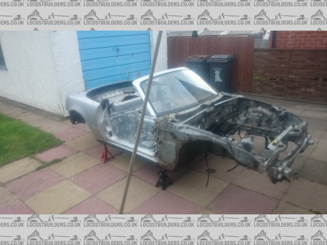
Chose my donor vehicle last Friday, it's a 1997 MX-5 with the 1.8 engine and 138 BHP. The car wasn't MOT'd, missing some interior and
had a missing backbox, none of which was a concern to me, and it's a runner.
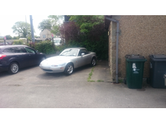
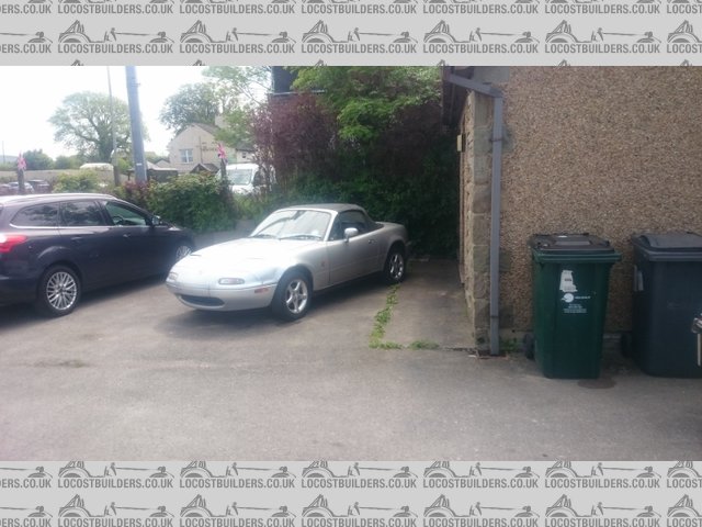
Donor Found
Big thanks to James (I think that was his name anyway) at Easily Fixed for going out of his usual delivery radius to
drop my car off, it was safely tucked away in the garage by 09:00 the next morning, much to the dismay of the daily driver Focus.
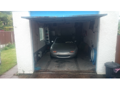
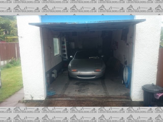
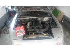
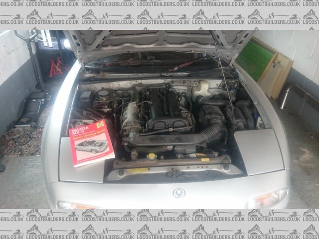
Donor Home
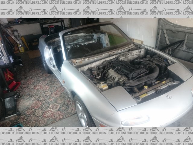
I've given it a more detailed look in the comfort of my garage, and all the bits I need seem serviceable. I paid a lot less than I was planning
to, so if there are any nasty surprises, I've got the spare cash and time to rectify them before the kit arrives. Busy this upcoming weekend with
handing out the wedding invites, but the weekend after, I'll have my 1 1/8" impact socket and my 14 year old brother available to help out.
Should make some good progress then 
Digimon - 16/6/15 at 08:57 PM
Good luck with your build Mick, looking forward to seeing progress.
I looked into building a MX-5 kit before my current car came up for sale
sdh2903 - 16/6/15 at 09:13 PM
Nice to see another blog. My kit will be ready end of September. I've just started stripping my 95 1.8 mk1 donor this week. It's not been
pretty so far. All I will say is thank god I had a 450lb ft impact gun and a decent compressor
The rear upright lower bolts and one driveshaft have yet to give up their fight and separate!!
micksalt - 17/6/15 at 09:53 AM
I've got an impact gun and a grinder at the ready for my tear-down. Thankfully I've got some experience of dealing with seized fasteners
from working on 100 year old restoration projects at the heritage railway I volunteer at.
sdh2903 - 17/6/15 at 10:59 AM
They're probably in better nick than the MX5 bolts
micksalt - 17/6/15 at 11:55 AM
quote:
Originally posted by sdh2903
They're probably in better nick than the MX5 bolts
'Tis probably true, can't beat an old-school Whitworth thread
micksalt - 17/6/15 at 12:03 PM
SaltysLittleHelper
My brother popped round to take a look at the car last night. The only bits I've done so far is remove the parts of interior left scattered
around the car by the previous owner and stripped the number plates and old tax disks off so I don't forget to remove these before sending the
shell off. I've found 2 VIN numbers so far that will need cutting off when the time comes to scrap the shell, are there any more hiding?
micksalt - 19/6/15 at 05:18 PM
Got an afternoon on the car today, and the Destruction Manual had arrived, so I got to work.
DestructionManual
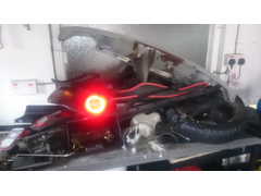
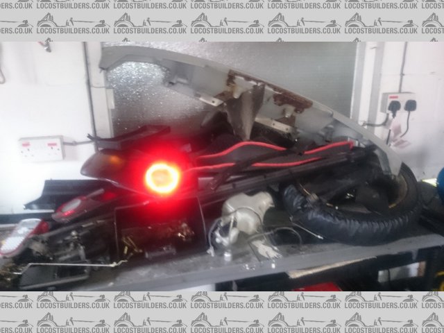
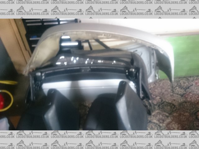
Wasn't too long before my 2-door car became zero-door without bonnet and boot too.
ZeroDoor
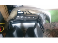
Getting topless
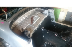
NoTop
Wiring everything, even circuits I won't be using just so I know they're safe to remove.
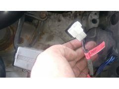

WiringLabels
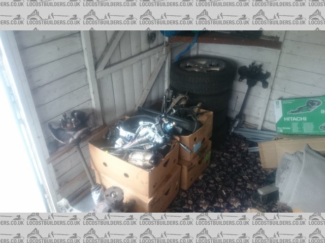
Bloody good job it's a big garage, the junk piles keep growing. Thankfully I have a backup shed behind the garage to act as a holding area.
JunkPile1
JunkPile2
Feels so good to have got started properly
micksalt - 24/6/15 at 06:20 PM
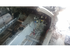
Had an MX-5 fanatic helping me yesterday with the strip down of the interior. That's Adrian with his head in the dash. It's surprising how
many folk want to help out, I almost feel like I haven't got enough MX-5 stripping to go around. Still, I can use all those offers of help on the
build I suppose.
AdeHelping
And Adrian's handiwork:
MoreLuxuryThanA7
Still more luxurious than a kit car in there. My first new part arrived today, courtesy of the bonus at work but shh, this doesn't count to the
budget Ok?
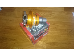
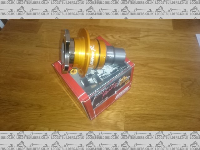
RapfixR
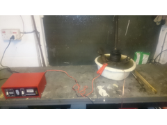
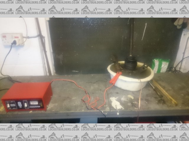
And today, scored a big victory. I've been fearing the rear hub nuts for ages with stories of split sockets, bent breaker bars and jumping on
scaffolding poles for leverage. My 1 1/8" impact socket arrived today, so I bit the bullet and gave it a go with my battery-powered impact
wrench. Was rather disappointed that it only took 5 seconds a side, I expected more of a fight. I've temporarily refitted the hub nuts so I can
roll the car about still, but at least I can make a start on the brakes now I don't need them to counter-hold against the hub nut.
More to follow Friday 
sdh2903 - 24/6/15 at 06:34 PM
Haha getting the hub nuts loose is the easy bit, wait til you try and get the shafts out and the wishbone bolts out, they really are fun
Looks like the strip down is going well, what spec did you go for with the MNR? Any plans for engine upgraditis?
micksalt - 24/6/15 at 08:58 PM
I had heard that part was fun, stories of cracked carriers when using a hydraulic press. At least that should provide some interest.
Spec? I'm just going for the 'just add donor' MX5 package with full roll cage and side impact bars. Nothing on the engine for now, but
fitting a Canems ECU (again, shh about the budget) so I've got the supercharger open to me in a few years' time.
kingster996 - 24/6/15 at 10:04 PM
Check out this thread ref supercharging, great read!
http://forum.wscc.co.uk/forum/index.php/topic/114587-breaking-the-magic-barrier-mx5-sdv-power-upgrade-project/
micksalt - 25/6/15 at 07:34 AM
That is a good read, and may be the way to go as a future upgrade. Wheels (13" if possible), 4-pot brakes and an LSD will come first on the
upgrade list though. The plan was to do a budget build, then upgrade later. However, things like the ECU and removable steering wheel make sense to do
now.
sdh2903 - 25/6/15 at 10:28 AM
Does your donor have an LSD or were you planning an upgrade?
Ashcroft transmissions do an aftermarket ATB that fits in the 1.8 diff. They are knocking them out on ebay cheap
http://m.ebay.co.uk/itm/321785023125?nav=SEARCH
They get very good reviews on the mx5nutz forum.
micksalt - 25/6/15 at 10:43 AM
Nothing in the spec suggests mine has an LSD, although I won't know for sure until I pop the driveshafts out. I planned on fitting the Ashcroft
unit as a future upgrade if it didn't have an LSD, seemed good value compared to some of the more famous brands, and I'm all the more
reassured that you've said it's been well reviewed.
[Edited on 25/6/2015 by micksalt]
micksalt - 25/6/15 at 03:15 PM
Presumably it's not just a case of draining the diff, cracking it open and swapping in the Ashcroft LSD. There's some very precise shimming
to be done isn't there?
micksalt - 26/6/15 at 07:36 PM
It had to happen, had a bloody awful day on the donor today, with the steering of all things. Stripping the bits that were in the car, not problem at
all:
NoHands
As for the other end of the rack: chaos:
NoRack
The clamping bolt that holds the lower universal joint to the rack was both seized, and heavily corroded on its head. Thankfully at the other end of
the joint the lower part of the shaft came away pretty easily, so I was able to remove the whole rack then. However, drilling out that lower bolt, I
wasn't quite in the middle of the bolt and nicked the threads on the universal joint. Two questions I have to the community, one is if I actually
need the lower joint for the Mazda build, the second is if so, where could I get one from?
Cheers
[Edited on 26/6/2015 by micksalt]
sdh2903 - 26/6/15 at 08:21 PM
I may well be wrong but I'm sure that Chris said the link from the mx5 column to the escort rack was included in the kit.
micksalt - 26/6/15 at 10:12 PM
quote:
Originally posted by sdh2903
I may well be wrong but I'm sure that Chris said the link from the mx5 column to the escort rack was included in the kit.
I'll fire off an email to Chris to check. That's great news if that is the case because neither the shaft nor rack (��� on eBay) were
damaged.
micksalt - 30/6/15 at 12:12 PM
I've got a reply from Chris, and I don't think I need the damaged joint from the donor. The reason I say 'think' is because I
wasn't very clear with my request.
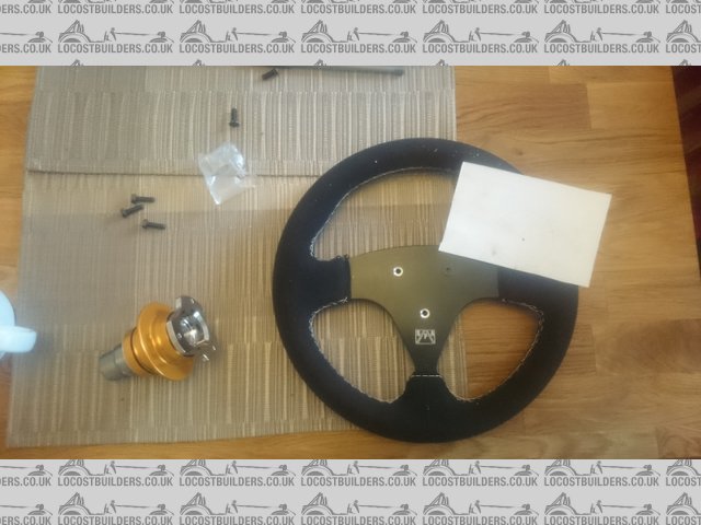
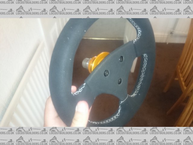
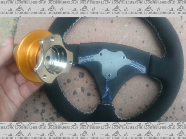
Whilst asking about welding the Works Bell boss onto the steering shaft, Chris made me realise that I've dropped the ball a bit. I purchased a
S.P.A. 270mm suade steering wheel. However, I need a padded steering wheel of course. Just deciding whether to add padding to the centre of the wheel
I have or temporarily fit a different fully-padded formula wheel for IVA. Ooops 
sdh2903 - 30/6/15 at 12:34 PM
Could you not just use the donor wheel set up until iva is out the way? My donor is a non airbag wheel if you need it come iva your more than welcome
to borrow it.
micksalt - 30/6/15 at 12:58 PM
quote:
Originally posted by sdh2903
Could you not just use the donor wheel set up until iva is out the way? My donor is a non airbag wheel if you need it come iva your more than welcome
to borrow it.
I'm thinking this may be the way to go. I thought I might as well get the boss welded on whilst the steering column was with MNR, however, it
looks like both the removable part and the chosen wheel could create IVA headaches for me. Might be best left until after the time, even though it
will be a little inconvient to have the column back off again to weld on the boss. My donor has the right sort of steering wheel for the job, but
thank you anyway for the offer of a loan of yours
sdh2903 - 30/6/15 at 01:46 PM
How come the column needs to go to MNR?
micksalt - 30/6/15 at 02:00 PM
quote:
Originally posted by sdh2903
How come the column needs to go to MNR?
Actually, I might be wrong there, it may just be the lower shaft that needs to go to them for lengthening since you're pretty much sat at the
back of the car.
I think I may have solved the steering wheel problem. It turns out you can buy self-adhesive 3mm thick neoprene foam. Got some on order so I can have
a play with it. Will be just the job if so, and probably neat enough to just leave on permanently.
[Edited on 30/6/2015 by micksalt]
jim87 - 2/7/15 at 02:15 PM
Mick, I think we spoke at Stoneleigh a month or two ago. Glad you hear you're on your way.
I've just about finished my Mazda Vortx.
Anyway, on mine the upper column had two short tubes welded onto it by MNR for mounting it to the scuttle. Also the lower shaft has the Mazda spline
at the top end, and an appropriate Escort spline at the other end for connecting to the rack via a couple of UJs.
Jim
quote:
Originally posted by micksalt
quote:
Originally posted by sdh2903
How come the column needs to go to MNR?
Actually, I might be wrong there, it may just be the lower shaft that needs to go to them for lengthening since you're pretty much sat at the
back of the car.
I think I may have solved the steering wheel problem. It turns out you can buy self-adhesive 3mm thick neoprene foam. Got some on order so I can have
a play with it. Will be just the job if so, and probably neat enough to just leave on permanently.
[Edited on 30/6/2015 by micksalt]
[Edited on 2/7/15 by jim87]
micksalt - 2/7/15 at 02:31 PM
Jim,
That's great news, I kicked myself when I damaged the lower universal joint, but since my shaft will have the wrong spline on the other end
anyway, and MNR will provide the appropriate Escort UJ, then it looks like I'm home and dry.
I was there at Stoneleigh, I was the guy with the mad sideburns that went out for a passenger ride in the orange Mazda-powered Vortx (can't
remember the guy's name, both of us forgot eye protection which was amusing). Glad to hear you're almost finished
Going to have another full session on the donor this Saturday. Hoping to get to a point I can lift the shell off the subframes and PPF assembly.
Cheers,
Mick
quote:
Originally posted by jim87
Mick, I think we spoke at Stoneleigh a month or two ago. Glad you hear you're on your way.
I've just about finished my Mazda Vortx.
Anyway, on mine the upper column had two short tubes welded onto it by MNR for mounting it to the scuttle. Also the lower shaft has the Mazda spline
at the top end, and an appropriate Escort spline at the other end for connecting to the rack via a couple of UJs.
[Edited on 3/7/2015 by micksalt]
jim87 - 2/7/15 at 04:17 PM
Yep, I remember the side burns
I spoke to you just after you'd got back from your drive out
micksalt - 2/7/15 at 06:26 PM
I think I can just about recall the face. I'll be better with faces and names come Stoneleigh 2016, even if I'm not finished, because I
suspect I'll be part of the MNR stable.
More happy progress today, didn't have enough time to get dirty, so I thought I'd tackle the steering wheel instead. I was a bit nervous
about this, particularly since the Rapfix gets in the way of marking holes straight through it. After a bit of thinking, I drew up a template in
Powerpoint at a PCD of 50.8 mm and with vertices spaced at 120 degrees. I stabbed a pencil through the centre of the template to engage with the
dimple on the steering wheel, and centre-punched at the vertices. I'm pleased to report that it was absolutely spot on, not a single hole had to
be enlarged for any mis-measurement
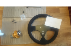
PerfectlyDrilled
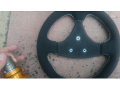
Now, after my oversight on the IVA requirements for the padded steering wheel, I bought Pack of: 5 x Self Adhesive Peel Off - Black
Foam Sheets 175mm x 135mm x 3mm . At first I tried cutting a rough shape first just to apply to the front face of the wheel, however, it looked
awful and peeled off too easily, which would upset Mr IVA. The holes were cut using a socket and a hammer
. At first I tried cutting a rough shape first just to apply to the front face of the wheel, however, it looked
awful and peeled off too easily, which would upset Mr IVA. The holes were cut using a socket and a hammer

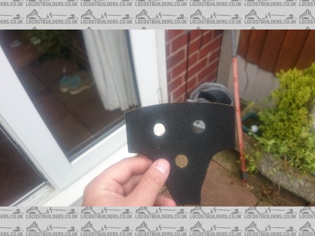
PadPrototype
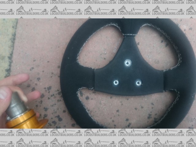
I decided that it would be better to wrap the sheets around the back of the wheel to give a better fit. As luck would have it, the sheets were
perfectly the right width, so I cut my holes again, peeled off the backing, and this time, folded around the back of the wheel, trimming to fit where
necessary.

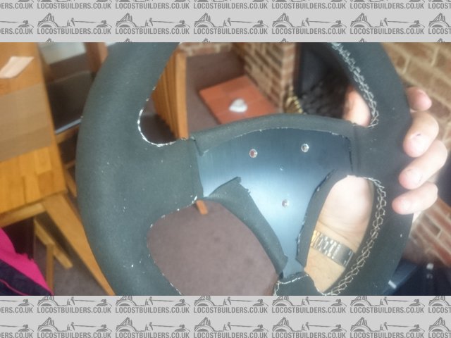
PadRear
And finally, I fitted it all to my quick-release boss. I might have another attempt at the foam covering, try to get the holes centred on the bolts,
but all-in-all, not a bad attempt for the second try.
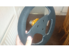
WorksBellFitted
[Edited on 3/7/2015 by micksalt]
micksalt - 4/7/15 at 05:12 PM
For information, you need a stronger glue to do the DIY pad that I've demonstrated. The glue sticks to the steering wheel alright, but the
neoprene itself peels from the glue where I've wrapped it around the back. I'll take the opportunity to make a slightly better job on the
holes positions, and use a hot-melt glue gun next time.
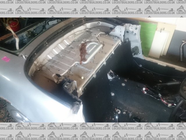
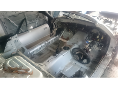
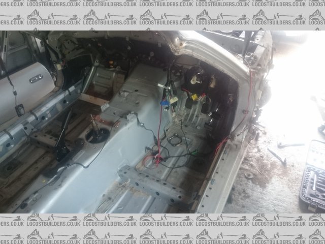
Back to the donor, there's not much of the wiring loom left to disconnect now. What that does mean is that the interior has become all
Italian:
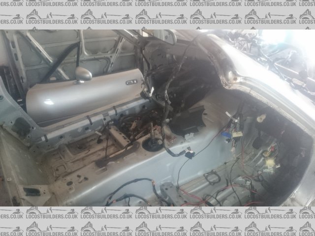
Spaghetti
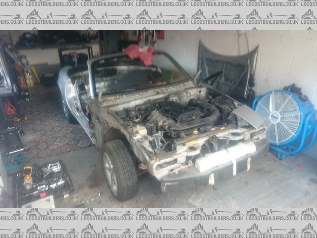
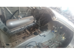
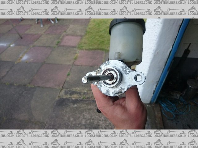
And the engine bay is looking very empty now having removed the carbon canister, air filter assembly, radiator, light motors, alarm, master cylinder,
bias valve, anti roll bar.

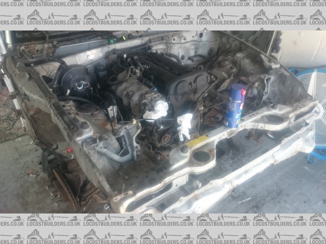
EmptyEngineBay
One thing I did notice is how much complexity there is for the emissions control systems. For instance, the purge control valve is not just a valve,
it's two valves, in series, like it's a critical system on an Apollo launch. I didn't expect such complexity for a 1997 car and
I'm glad not a lot of it will make it into the kit car. One last thing, I temporarily, and loosely fitted the steering rack so that the front
wheels didn't act like a dodgy supermarket trolley when I push it outside to lift the body off. Speaking of lifting the body, I think that could
be the next session
micksalt - 10/7/15 at 07:14 PM
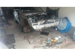
Will upload some photos later, but I am finally ready to lift the body off. Next session, assuming dry weather, the MX5 is going topless.
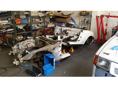
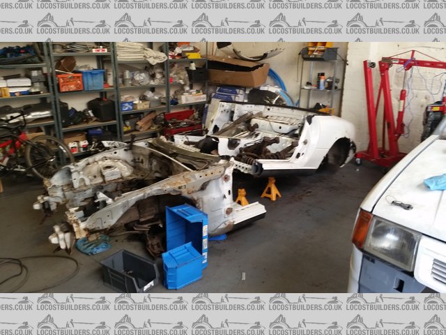
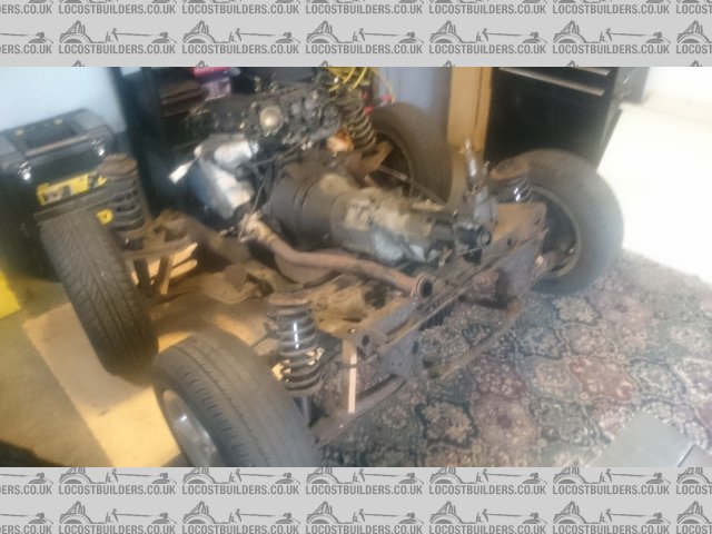
micksalt - 19/7/15 at 05:28 PM
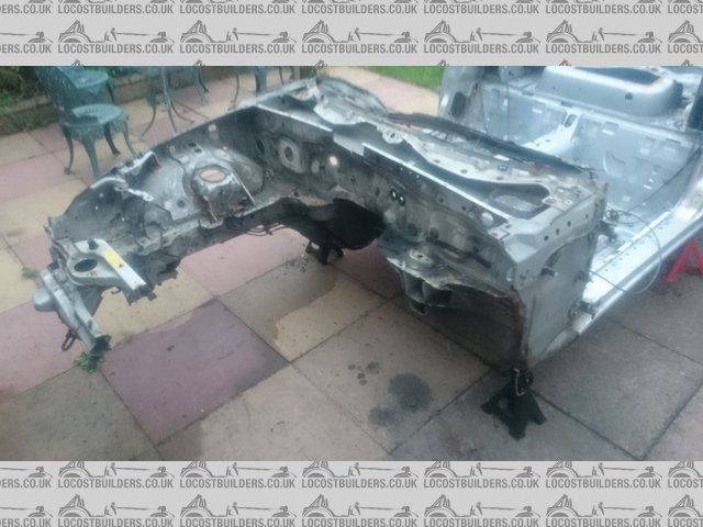
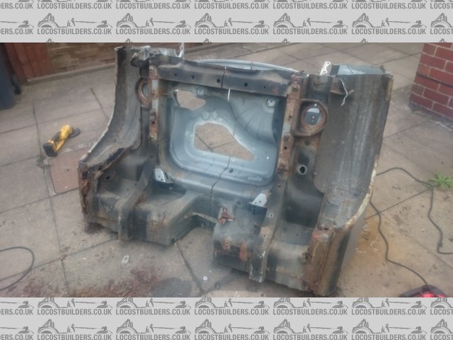
Finally, we have lift-off, so glad my mother convinced me to go for the 2 ton crane over the 1 ton, I'd missed two 14 mm head bolts at the front,
and another two at the back, so ended up lifting the car

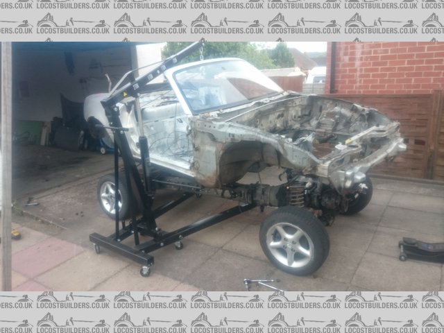
LiftOff
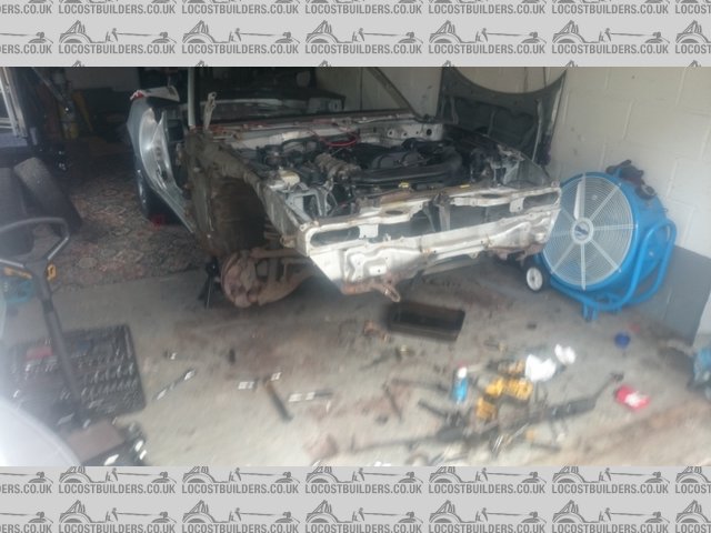
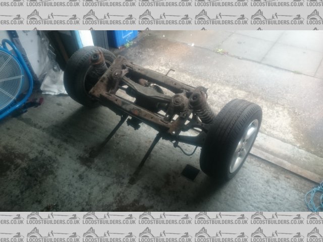
Now we're down to the rolling subframe, disassembly should come along nicely, and I can put the daily driver away. That is after I've
cleared the junk pile into stuff to use, stuff for sale, stuff for weighing in and stuff to bin. Any MX-5 owners looking for an obscure part that they
know I won't be using, shout up now.
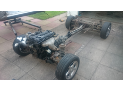
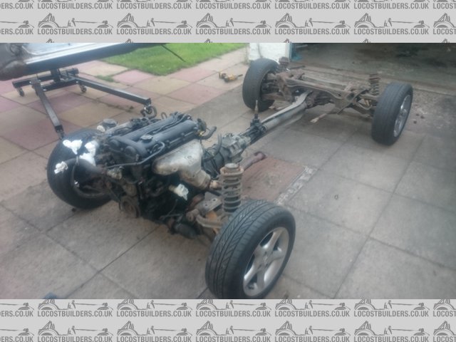
RollingSubframe
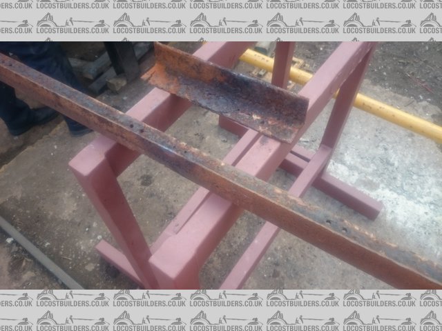
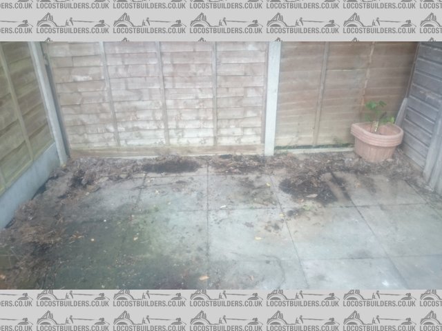
Not sure the other half is convinced about the latest garden furniture
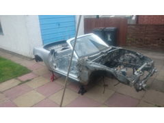
GardenFurniture
She'd be even less impressed about my other purchase. Again, shhhh, doesn't count to the budget I declared to her 

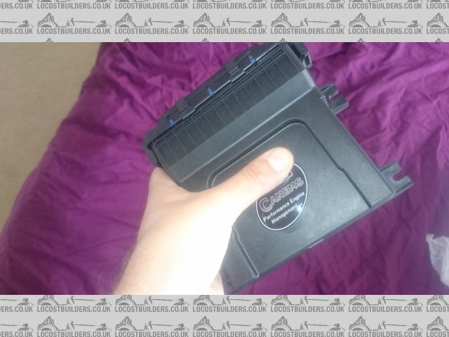
Canems
paulc - 19/7/15 at 06:10 PM
Nice garden furniture!
Could be worse though
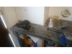
This is my kitchen at the moment:
Paul
micksalt - 19/7/15 at 06:46 PM
Paul,
I am using your photo as evidence to the wife to be why my MX-5 shell in the garden isn't so bad.
Cheers!
micksalt - 20/7/15 at 02:56 PM
Shell is getting in the way of the washing line, tomorrow's job is cutting it up.
micksalt - 24/7/15 at 05:53 PM
Progress was rubbish on the shell cut up. A 5" battery powered grinder is definitely not the way to go

SlowCut
sdh2903 - 24/7/15 at 06:02 PM
Haha. 9" angry grinder is the way to go.
Cutmx5
micksalt - 24/7/15 at 06:05 PM
Having got myself a 2000 watt, 9" grinder, today's task was to finish cutting up the shell. Unfortunately, rain stopped play, so I turned my
attention to the rolling sub-frame assembly. Not quite as easy as I'd hoped, but I overcame the issues. One curious thing is that because the
bolts are so long, the spring tension of the bolt makes the impact gun pretty useless, 2' breaker bar it was then However, the front bolt of
the diff-to-PPF came undone from its threads alright, but got jammed trying to take it out. on further inspection, the lower diff spacer was actually
cracked, and the bolt had seized itself to it where the water had got in. Took a little thinking, but I undid the connections to the PPF at the front
first and then removed the prop-shaft. I could then put the assembly on end and angle-grind through the cracked spacer whilst causing no damage to the
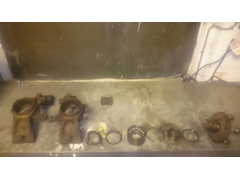
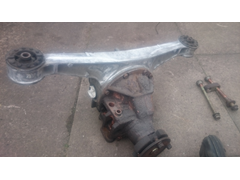
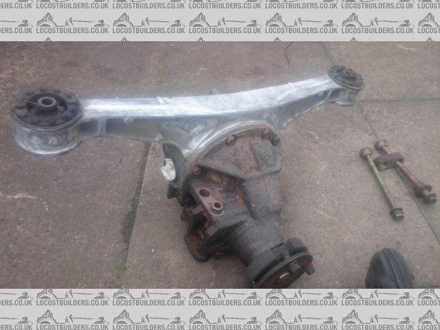
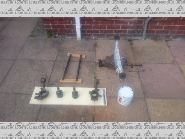
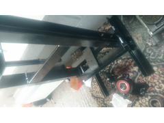
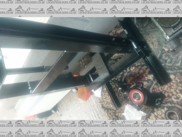
PPF. After all that fun, I ended up with these.

FrontSub

RearSub
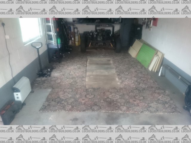
After moving the junk pile into the back shed, I created a SWB MX-5 in the garage.

ShortWheelbase
Finally, I have a usable garage again. I took the opportunity to cut the carpet around my inspection pit to save the faff of rolling it up each
time.
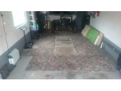
TidyGarage
And crucially, I could get the daily driver back in the garage. I had declared it as 'normally garaged' to the insurance folk, and was
beginning to stretch that definition of 'normal' having had it outside for a month. Of course, come renewal this October, the daily driver
is getting permanently evicted, so I'll declare it as so.
Next dry day, excluding tomorrow due to heritage railway duties, I'll get that shell gone.
Cheers
micksalt - 29/7/15 at 08:33 AM
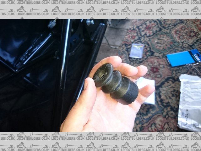
Another "I broke something, do I need it?" question. The spacer under the differential (Part number 27-158 on page 2-H 3 of the
Parts Manual) got damaged on removal. Do I need it? Looks like
they don't tend to get sold seperately, so I may need to get a spare diff just to get this part, or use it as an excuse to get a Torsen
Cheers 
jim87 - 29/7/15 at 03:46 PM
quote:
Originally posted by micksalt
Another "I broke something, do I need it?" question. The spacer under the differential (Part number 27-158 on page 2-H 3 of the
Parts Manual) got damaged on removal. Do I need it? Looks like
they don't tend to get sold seperately, so I may need to get a spare diff just to get this part, or use it as an excuse to get a Torsen
Cheers
If its the part I think you mean, then yeah, you'll need it. Here's a pic of mine.
You mean the part between the diff and the chassis ?
Description
[Edited on 29/7/15 by jim87]
micksalt - 29/7/15 at 07:50 PM
Cheers Jim for clarifying, as luck would have it, Autolink had the part in stock for a mere tenner (+ VAT + Delivery). I've currently got the
bolt soaking in oil to free the cylindrical spacer from it. It was these two seizing together that caused the spacer to crack in the first place

Anyway, the rest of the project is going well. The body took no time at all with the addition of a 9" grinder

FinalCut
Leading to a self-assembly MX-5 body kit.

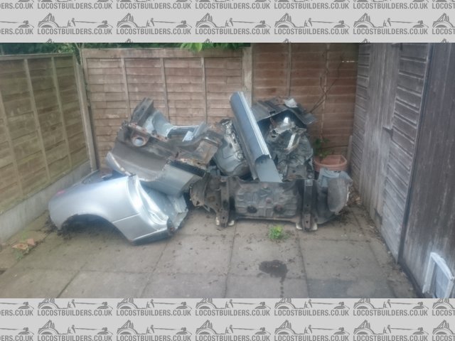
SelfAssemblyMX5
Crucially giving me a clear patio. Needs a good clean though after all the rust that fell off the donor. I've done the fellowship of the road a
favour taking this off the roads.

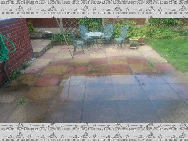
CleanPatio
micksalt - 30/7/15 at 07:18 AM
Jim, did you reuse the diff bolts from the MX-5 or were new bolts provided with the Vortx kit? One of the bolts had to be cut due to it being seized
in there and the other has a mashed head and threads after being used as a drift to get the stuck one out. Ta in advance.
jim87 - 30/7/15 at 07:50 AM
quote:
Originally posted by micksalt
Jim, did you reuse the diff bolts from the MX-5 or were new bolts provided with the Vortx kit? One of the bolts had to be cut due to it being seized
in there and the other has a mashed head and threads after being used as a drift to get the stuck one out. Ta in advance.
They were brand new ones - supplied by MNR.
Destruction job on the MX5's looking good, you'll be able to fit it all into a wheely bin soon
micksalt - 30/7/15 at 08:41 AM
quote:
Originally posted by jim87
Destruction job on the MX5's looking good, you'll be able to fit it all into a wheely bin soon
A lot of miscellaneous items have already ended up in the Wheelie bin. The component-form MX-5 will be taking two trip in the back of the Focus to the
scrap metals dealer, partly for a bit of cash, partly to see the look on their face as I deliver a car in bits
That's great news about the bolts, now I've just got to find where I put the top-hat spacer (part number 39-723 on page 2-C 6 of the
Parts Manual). Unless I don't need it of course.
micksalt - 30/7/15 at 10:04 AM
Ah, I think the reason I cannot find it is that it was wedged in the spacer and also suffered at the blade of the angry grinder. I've found one
for sale anyway, I'd rather have it and not need it than come to fit it, need it and not have it
jim87 - 30/7/15 at 10:19 AM
Where does it go ? Between the bolt head and PPF ? If so I don't think you'll need it. If it fits into the spacer (the one that cracked and
you got from autolink) then you might well need it if it makes the bolt whole the correct size ?
micksalt - 30/7/15 at 10:26 AM
It does fit into the spacer that I cracked. I remember there being a strange section in the cut spacer that now I think of it would have been the
top-hat spacer, albeit wedged in so tightly I couldn't make out a difference in the cut. I bought a full bolt set that included the top-hat
spacer and the bolt that secures the spacer I broke onto the diff housing. I'll pretty much make my money back selling the bolts off seperately
so it'll only have been a couple of quid for peace of mind. Only thing left to do is unseize the cylindrical spacer from the cut bolt that goes
between the diff body and the spacer I broke.
Is anyone still with me? I've confused myself
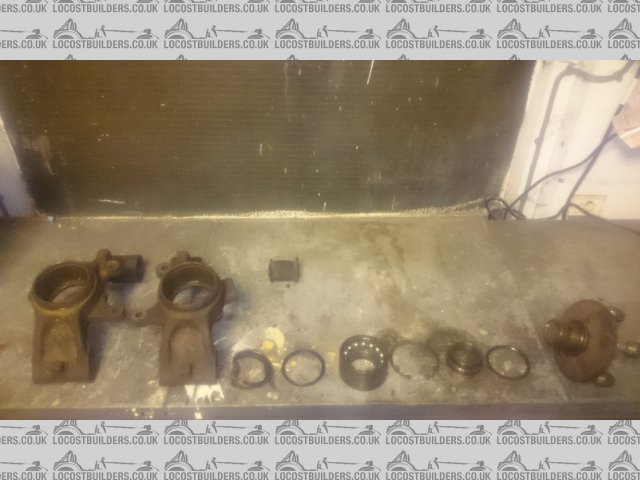
micksalt - 30/7/15 at 07:27 PM
Another productive day, cylindrical spacer successfully removed from the shoulder bolt, replacement spacer fitted (lots of copper grease) and the
diff, drive-shafts and hub carriers successfully removed from the rear sub-frame.
Now for the part that's got me puzzled, what tools and techniques are folk using to remove the push-in shafts from the diff? I've tried
various smaller levers in there, but no budge at all. Am I being too gentle, do I need a proper pry-bar?
sdh2903 - 30/7/15 at 07:50 PM
Just grab a hold and give it a good pull. (No pun intended)
micksalt - 30/7/15 at 08:36 PM
quote:
Originally posted by sdh2903
Just grab a hold and give it a good pull. (No pun intended)
Ah right, I wasn't sure whether to do that for fear of damaging the CV joints. I'm going to renew the gaiters anyway so I can always inspect
for damage then. Thanks.
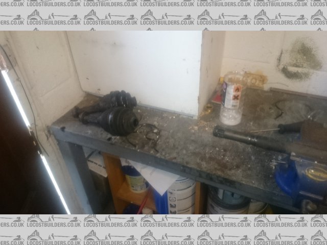
micksalt - 31/7/15 at 05:31 PM
Turns out I was being a big Jessie about it, put my feet on the diff, and gave the drive-shafts a few hard tugs and they were free. CV joint feels
fine too.

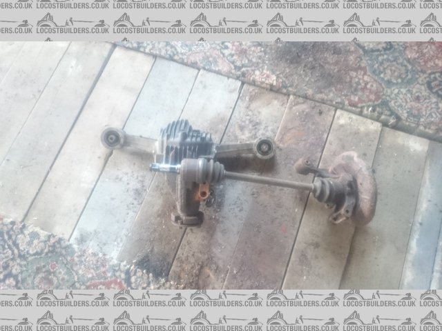
GoodTug
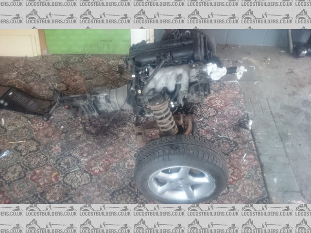
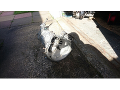
And it was a very productive afternoon, got the engine and gearbox assembly free from the sub-frame pretty easily once I'd figured out how to
attach my load leveller to it all.
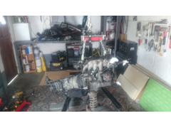
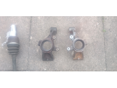
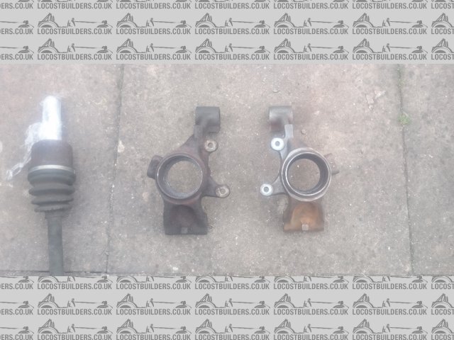
FlyingEngine
The front hub carriers and brake assemblies put up very little fight, with just the lower near-side ball joint nut needing the delicate touch of the
5" battery grinder. That's the teardown complete, I can now move onto parts restoration
Not wanting to feel left out though, I only made a half-hearted attempt to remove the drive-shafts from the rear hubs. The hub nuts are loose of
course, but I'd prefer to leave them standing drowning in some penetrating lubricant before I tackle them in anger
micksalt - 5/8/15 at 04:03 PM

DonorPack
Well, that was a lot of effort saved. Invited an MX-5 enthusiast round to help himself to a few of the parts for free, he took the lot and even gave
me some cash for them. Even took a section of the chassis rails (middle section, the only good bit) for welding into a damaged part of his chassis and
the wing that I thought I'd distorted too much to be of use. Much hassle saved compared to getting rid of it all through eBay
Just got to get rid of the scrap pile now and I'm sorted. The guy that popped round is bringing his industrial-grade hub puller sometime this
week to get my rear hubs free of their drive-shafts.
Rocket_Rabbit - 11/8/15 at 04:13 PM
A very nice read that! Keep it up matey!
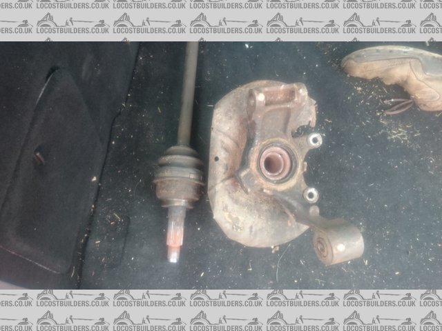
micksalt - 14/8/15 at 05:17 PM
Cheers Rocket_Rabbit
Hands up if anybody can guess what problem I've currently run into.
DriveshaftRemoval
Annoyingly, the other driveshaft popped out with not much of a fight using a hub puller and impact wrench, and that was a little more corroded around
the hub nut due to the absence of the dust cover. I'm going to need a new CV joint on the end of this driveshaft at the very least because I was
walloping the hub nut so hard I stripped the threads. Oh well, can always buy these parts ready separated if I don't figure it out
By the way, Amazon are currently selling those Absaar chargers for just a shade over �20 delivered. If you can swap the 2-pin European plug for a
3-pin British plug, well worth getting.
[Edited on 14/8/2015 by micksalt]
sdh2903 - 14/8/15 at 07:46 PM
Mine was exactly the same. One side easy. One side a pig. Get it in a press and give it a tap. As long as you don't muller the hub (like I
did:mad as you say the cv joints are easy to come by.
micksalt - 15/8/15 at 06:42 PM
One of the advantages of working at a heritage railway, lots of people with years of experience of getting old metal to part. After consultation with
a Fellow of the Institute of Mechanical Engineers, the prescribed course of action was described as "get it f-ing hot and then f-ing hit
it". Even better, our resident expert at getting things hot then hitting it offered to do it whilst I was running the passenger service. Very
pleased to see the two parts apart whilst driving past. Going to renew the bearing for sure, probably the hub too since he did get it "bloody
hot". Glad I chose not to struggle on my own on this one.
[Edited on 15/8/2015 by micksalt]
prawnabie - 15/8/15 at 09:25 PM
The rear bearings are fit once only as i found out!
micksalt - 15/8/15 at 09:29 PM
quote:
Originally posted by prawnabie
The rear bearings are fit once only as i found out!
I thought so too, they tend to split between the inner and outer races when you attempt to remove them. I'm replacing bearings as a matter of
course, but I think, given the trauma sustained by the hub under the action of the hub puller and the heat, I might replace that too. It was allowed
to cool naturally, no quenching was involved, but since it's looking a bit blued, I'm not sure I want to take the risk that it has hardened
and become brittle.
prawnabie - 15/8/15 at 09:49 PM
I snapped and ear off the rear upright trying to press the flange out of the bearing, so I bought a second hand upright + flange. After changing the
bearing in that I realised the flange was bent! (car it came off must of hand a smash). The new bearing just fell apart whilst trying to push the
flange out again!
micksalt - 17/8/15 at 07:09 AM
I've got myself booked in at MNR to pay my deposit on 12th September. I'm going to take the steering column, propshaft and front uprights
with me for modification so I can pick the whole lot up in one go in November. Also going to take my Works-Bell boss to get welded on too.
I've decided that I'm keeping the build basic, with the intention to upgrade in the future. However, one thing that is very permanent is the
roll cage. Is it worth forking out the extra for the T45 cage over the CDS? What sort of weight difference are we talking?
micksalt - 25/8/15 at 06:22 PM
As a proportion of the build cost, the T45 cage isn't that much more, may as well.
Well, here's the heavy-duty jig used to separate the hub from the driveshaft, using the biggest oxy acetylene torch we could find:

BigJig
And the happy outcome:

FinallySplit
I had an evening of keeping clean last week, so I turned my attention to finally sorting the steering wheel padding. The prefabricated pad I ordered
was the wrong shape, so back to my neoprene wrap. This time, I wrapped further around the wheel, cutting around the Rapfix to maximise the sticking
surface. Having had some practice with the hot-melt glue gun, I was able to make a much neater job of securing the edges. Pleased to say, this one
didn't peel back

PaddedWheel
IVAFriendly
And having subjected the hub and bearings to so much heat, it's sensible to replace. I stripped the hub, using a hammer and socket to drive the
hub out, then using the part of the bearing that had stuck to the hub to use as a drift to knock the bearing assembly out, having to use an old PPF
bolt as a drift to do the last bit (moving around the bearing as I went). As luck would have it, the old bearings were perfect to use as a support to
drive the bushings out in the vice using a socket on the other side. I'll use a press for reassembly though, either bought or borrowed.
RearHubStrip
[Edited on 25/8/2015 by micksalt]
micksalt - 28/8/15 at 04:48 PM
Well, a job I kept putting off has been done today; taking the scrap metal to be weighed in. All clear again behind the shed:

WeighingIn
It took three trips in the Focus Estate, the interior has suffered a bit for it but at least I've disposed of it all responsibly. And how much
was my 340 kg of MX-5 metal bits worth?
�13.60
Thanks China for having a recession at the same time as I could be bothered to weigh in
Anyway, fun jobs ahead, got to get myself some zinc-phosphate primer and I can start making things pretty. Pro-tip however, when you make a list of
all the parts you wish to replace with new, don't ever add a 'cost' column, and certainly don't ever add them up. However, the
donor came in massively under budget so all is well
l5tuy - 3/9/15 at 06:59 AM
13 quid doesn;t sound like alot for that weight of steel, I was hoping to get good money for my shell, not anymore......
Stu
micksalt - 3/9/15 at 08:16 AM
I think if you shop around, you can get up to �60 a tonne, but this place was convenient to say I had to make three trips.
sdh2903 - 3/9/15 at 08:18 AM
Yep scrap price Is on its arse. A mate collected my shell. 12 or so steel radiators and half a vauxhall nova and got 35 quid. The last donor o
scrapped I got 100 and the guy came and collected it.
Mick, just to pass on a nugget of info, I ordered replacement outer cv joints due to damage when removing from the rear upright. There are a couple
of variants for the 1.8 cars. Some have 22 internal splines some have 30. I've just had a right faff sending back 2 sets, finally got the right
ones.
micksalt - 3/9/15 at 11:23 AM
quote:
Originally posted by sdh2903
Mick, just to pass on a nugget of info, I ordered replacement outer cv joints due to damage when removing from the rear upright. There are a couple
of variants for the 1.8 cars. Some have 22 internal splines some have 30. I've just had a right faff sending back 2 sets, finally got the right
ones.
Cheers fella, I'm going to make things doubly complicated because I've ordered new hubs as well. I might wait until they arrive then count
the splines before ordering the CV joints on the back of this information. It'll be the CV joints that have to fit the hubs because the hubs are
coming all the way from the US of A.
sdh2903 - 3/9/15 at 11:48 AM
I'm intrigued which hubs you going for? From my now near expert knowledge on the subject. Most of the shafts have 26 splines in the hub.
It's the splines on the end of the driveshaft that push into the CV that vary.
micksalt - 3/9/15 at 05:29 PM
quote:
Originally posted by sdh2903
I'm intrigued which hubs you going for? From my now near expert knowledge on the subject. Most of the shafts have 26 splines in the hub.
It's the splines on the end of the driveshaft that push into the CV that vary.
Ah, got you. No, nothing special about the hubs coming in from across the pond, just a third of the price of what I can get them here. I've got
time on my side to wait for them to arrive, although I doubt the two year warranty would be much use if I had to send them back
micksalt - 11/9/15 at 07:25 AM
quote:
Originally posted by sdh2903
Some have 22 internal splines some have 30.
I'm so glad you pointed this out, because I wouldn't have bothered checking, and realised halfway through the CV joint replacement with
everything greased up. 22 splines on the end of my driveshaft, 30 in the CV joint. Doh!
May I ask where you got your 22-spline CV joint from? I can find 22-spline ones with ABS, but I need ones without ABS, unless the only difference is
the actual ABS ring and either will fit?
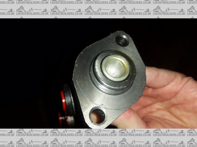
micksalt - 11/9/15 at 08:49 PM
CVJointOff
Top tip, do this stage before ordering your CV joints and count your driveshaft splines. For those that have knackered the end of the CV joint getting
it to part company with the hub, to get to this stage you just take off the driveshaft gaiter, hold the shaft in a vice and tap the CV joint off.
It's held on by friction to a little C-clip on the driveshaft, a bit similar to what holds the other end in the diff.
Early start tomorrow, off up North to order my kit
sdh2903 - 11/9/15 at 09:04 PM
You not ordered yet?
Ask em while your there when mine will be ready hopefully I'm still on for the end of the month.
micksalt - 11/9/15 at 09:13 PM
quote:
Originally posted by sdh2903
You not ordered yet?
Nope, wanted to make sure the garage was definitely clear of donor vehicle before I even considered it. Hopefully I can collect on November 14th after
getting back from my honeymoon. I'll ask about yours.
sdh2903 - 11/9/15 at 09:15 PM
Nice wedding present!!
micksalt - 14/9/15 at 09:16 AM
All ordered now, will upload the obligatory factory tour photos when I can get to my usual PC. Came in a smidgen cheaper than expected too because
there were parts and services included that I thought I had to supply
l5tuy - 15/9/15 at 11:57 AM
I ordered 3 weeks ago, spent last weekend stripping the mazda.
I'll post pics later.
Be interesting to follow similiar builds over the next few months.
Stu
micksalt - 15/9/15 at 04:28 PM
Likewise, will be interesting to follow your build too. Let me know if I can be of any assistance to your MX-5 teardown.
l5tuy - 15/9/15 at 07:25 PM
Cheers, Mazda is stripped however. Got the rear passenger driveshaft removed from hub tonight thanks to a hydraulic puller, was seized solid and
seeing how dry it was I'm not surprised.
Stu
jim87 - 18/9/15 at 03:50 PM
quote:
Originally posted by micksalt
I've got myself booked in at MNR to pay my deposit on 12th September. I'm going to take the steering column, propshaft and front uprights
with me for modification so I can pick the whole lot up in one go in November. Also going to take my Works-Bell boss to get welded on too.
I've decided that I'm keeping the build basic, with the intention to upgrade in the future. However, one thing that is very permanent is the
roll cage. Is it worth forking out the extra for the T45 cage over the CDS? What sort of weight difference are we talking?
Mick - I meant to ask, what are MNR doing to the front uprights ? I never asked what they'd done to mine. Is it for the track rod ends ?
micksalt - 20/9/15 at 06:20 PM
quote:
Originally posted by jim87
Mick - I meant to ask, what are MNR doing to the front uprights ? I never asked what they'd done to mine. Is it for the track rod ends ?
No idea, I just assumed they drilled and tapped them for the cycle wing supports. I'll find out in November I guess.
micksalt - 28/9/15 at 07:41 AM
Wedding planning consuming my time at the moment. However, I have just received the 22-spline CV joints and all the required paints so I can carry on
with the parts restoration.
micksalt - 12/10/15 at 05:43 PM
A couple more distractions, first of all, the gates needed to come in for a repaint.
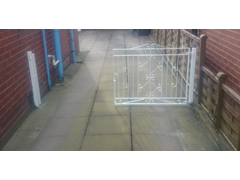
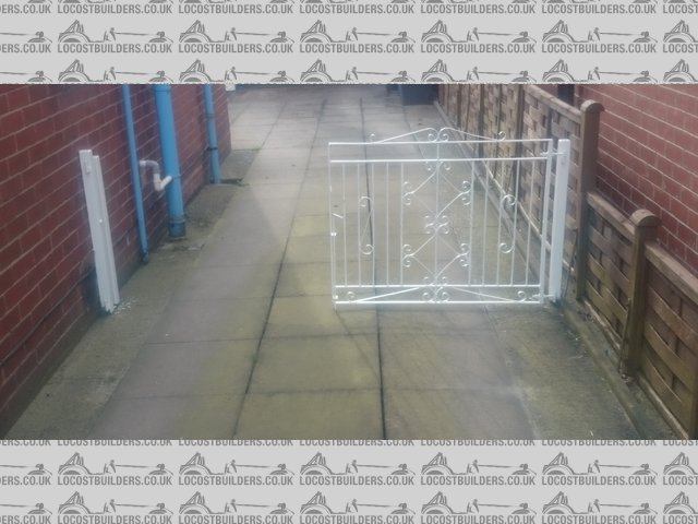
GateDistraction
And then the tin-top needed rear pads and brakes, and was due its 2-yearly hydraulic fluid refresh. Brakes went fine, and gave me an excuse to use the
pit, but obviously the maintenance department at British Transport Police couldn't be bothered refreshing the fluid in the clutch, it was pretty
dark. Managed to screw up the clutch fluid refresh and ended up with a lot of air in the system to the point I couldn't move the car However,
it turns out that I was just bringing the pedal back up too quickly and creating a vortex in the brake fluid reservoir that sucked in air. All sorted
now though
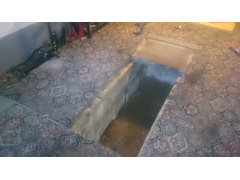
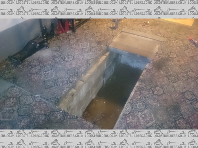
DownPit
So back to the kit car it was. The diff was pretty filthy with some very thick areas of rust.
DirtyDiff
Whilst I do have electrolysis equipment handy, for the small items it was just as easy to use the wire brush in the angry grinder.
Cleaning
And so it was all cleaned with spirit and prepared for painting. CV joints were removed from the drive-shafts to aid painting, for inspection and to
pack with fresh grease and put on new gaiters.
AwaitingPrimer
And the primer I used was great stuff, it's a quick-drying zinc-phosphate primer and boy did it dry quick! By the time I'd done the first
coat on all the parts, I could lay down the second coat. Really stuck fast to the surface, except the really recessed parts of the diff where there
was obviously a touch of oil still left.
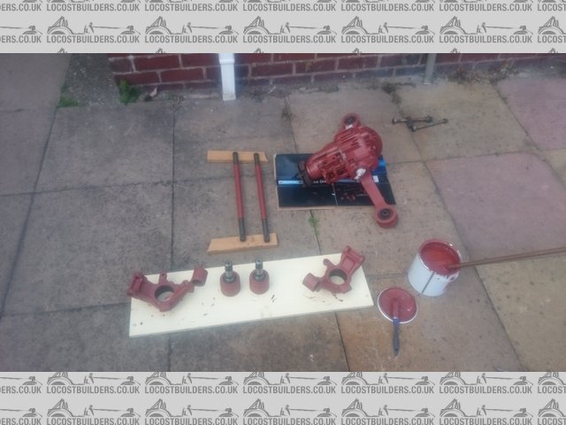
Primed
Unfortunately, the undercoat I've put on is not so fast drying, so that was me done for the day. The parts will eventually have 6 layers of
paint, two of primer, two of grey undercoat and two of black gloss. The idea behind using different colours is that I can see where the paint has
chipped and in need of a touch-up. If I see red, I know it's definitely in need of a touch-up. Unfortunately, I quite like the gunmetal grey of
the undercoat, but I've already bought the black gloss.
[Edited on 12/10/2015 by micksalt]
micksalt - 12/11/15 at 08:13 AM
Driveshafts and hubs ready for reassembly, chassis has now been built according to Chris at MNR so I'd better get a move on. Unfortunately, got a
diesel leak on the daily-driver to deal with tomorrow afternoon
l5tuy - 18/11/15 at 09:16 PM
Exciting times for you.
Seems MNR are having staff issues and therefore my kits been delayed. Chris mentioned 1 person was in front of me, wonder if it's you Mick?
It's my first kit car race, race to completion :-)
Stu
sdh2903 - 18/11/15 at 09:36 PM
Yep I'm waiting for a chassis too. Apparently a problem with poorly welders.
l5tuy - 19/11/15 at 07:55 AM
SDH2903 - I thought you had taken delivery of your kit, maybe your the one in front of me then........ The plot thickens
Do you have an estimate when yours will be done? I'll be into December now i think.
Stuart
sdh2903 - 19/11/15 at 08:19 AM
I have a chassis. But am waiting for a replacement. Long story. MNR have been great but am getting a smidgen frustrated now as I'm somewhere in
early December now.
micksalt - 19/11/15 at 09:07 AM
quote:
Originally posted by sdh2903
I have a chassis. But am waiting for a replacement. Long story. MNR have been great but am getting a smidgen frustrated now as I'm somewhere in
early December now.
Looks like I will have more time to finish restoring and tarting up everything then.
micksalt - 27/11/15 at 01:40 PM
The eBay press required a little ingenuity to get set up correctly, but it worked incredibly well.
Press
Rear hubs were rebuilt in next to no time.
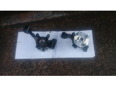
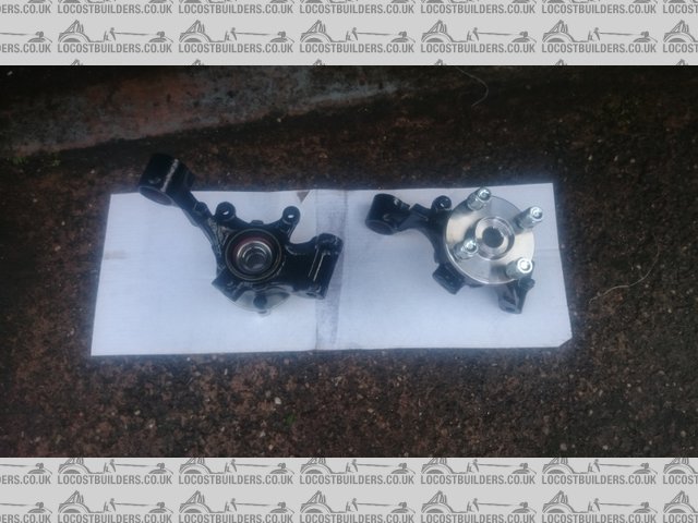
RearHubRestored
And trial assembled on the restored driveshafts. Plenty of anti-seize paste will be going on between the driveshaft and the hub, not going to go
through all that fun again if I need to in the future.
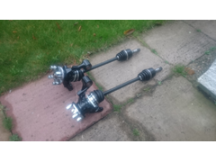
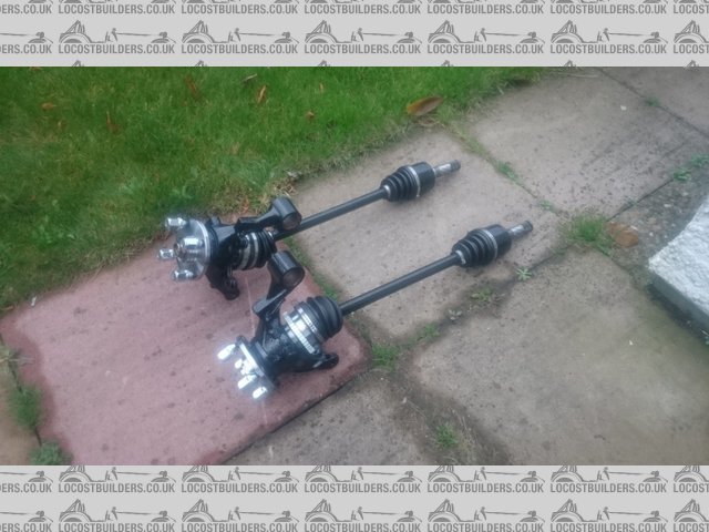
DriveshaftsRestored
Just got to get the daily-driver fixed these days, there's a good reason no one has built a common-rail powered kit car
micksalt - 2/12/15 at 08:12 AM
19th December is my provisional collection date. Talk about a great Christmas present
Digimon - 2/12/15 at 10:18 AM
Nice, I bet you can't wait to start building the car up
micksalt - 3/12/15 at 08:33 AM
quote:
Originally posted by Digimon
Nice, I bet you can't wait to start building the car up
Very much so. However, first up will be the cosmetic restoration of the front hubs and propshaft. Whilst I have the paints out, I'll tart up the
engine too. Going to leave the gearbox in bare aluminium though.
micksalt - 15/12/15 at 10:32 AM
What are folk doing about Goods-in-Transit insurance and build-up insurance? I'm struggling to find places to get this sort of cover, the best
offer I've had so far is a road risk policy that will cover transit and build for �160, but I cannot imagine getting any miles covered within the
next 12 months so it seems a bit wasteful.
[Edited on 15/12/2015 by micksalt]
ElmrPhD - 15/12/15 at 04:27 PM
Hey guys,
Just so you know...I was at MNR with urgent issues at the end of November and I can assure you that Marc was running around like a mad man from early
in the morning to late at night trying to get the backlog of chassis work taken care of while dealing with my issues at the same time. He is
incredibly productive - I was amazed at how much he could accomplish simultaneously with my stuff as well as the backlog. They normally had 2
full-time welders, but one got sick (it happens, eh?) and one mysteriously disappeared or something like that. My appearance on the scene was at a
particularly bad time. But they did their best...and their best is pretty damn impressive!
Just so you know...
Steve, in the NLs
micksalt - 17/12/15 at 02:51 PM
I was quite surprised, given the trouble they've had that my build was only delayed by 2-3 weeks.
jim87 - 18/12/15 at 10:22 AM
quote:
Originally posted by micksalt
What are folk doing about Goods-in-Transit insurance and build-up insurance? I'm struggling to find places to get this sort of cover, the best
offer I've had so far is a road risk policy that will cover transit and build for �160, but I cannot imagine getting any miles covered within the
next 12 months so it seems a bit wasteful.
[Edited on 15/12/2015 by micksalt]
I never bothered with in transit insurance, but I did check with my house insurance and they said they'd cover anything in the garage - even car
parts. Not sure if they'd have paid up if the worst happened, I was always a bit unsure.
I got build up insurance around about the time I got the car onto its wheels. Was about �130 I think
micksalt - 18/12/15 at 11:42 AM
quote:
Originally posted by jim87
I never bothered with in transit insurance, but I did check with my house insurance and they said they'd cover anything in the garage - even car
parts. Not sure if they'd have paid up if the worst happened, I was always a bit unsure.
I got build up insurance around about the time I got the car onto its wheels. Was about �130 I think
In that case, �151.43 for build-up insurance and goods-in-transit insurance doesn't sound too bad (Adrian Flux). Just goes to show what little
road-risk our insurers think we are
micksalt - 21/12/15 at 05:49 PM
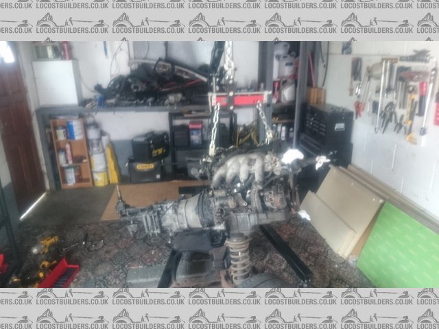
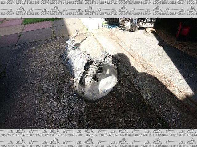
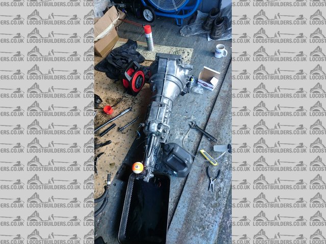
In anticipation of the new arrival, I decided to get the engine and gearbox split so I could put them somewhere sensible. Also, I'd rather not
trip and impale myself on the gearstick.
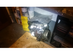
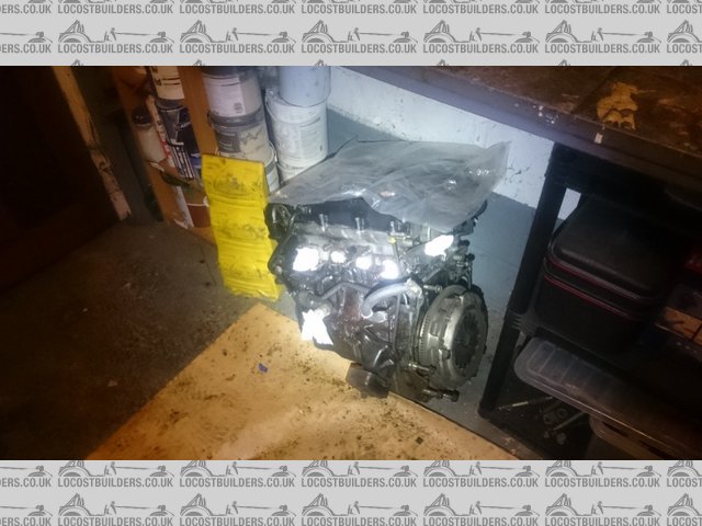
Engine
Engine is due a clean, paint, new timing belt kit and clutch.
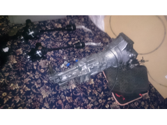
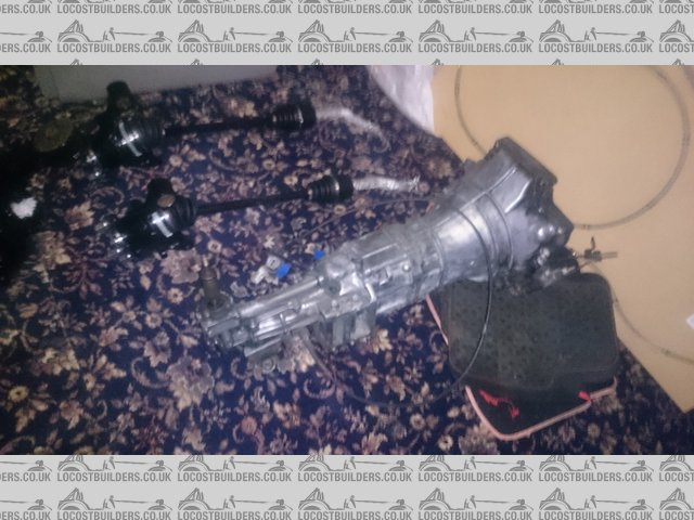
Gearbox
Gearbox just needs a clean, turret seal renewing and filling up with gearbox oil too. I can see why the MX-5 is becoming a popular donor choice, that
gearbox is ridiculously light.
[Edited on 21/12/2015 by micksalt]
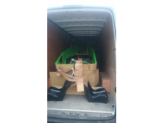
micksalt - 21/12/15 at 05:54 PM
Turns out that the Mercedes Sprinter with 4.4 m load bay was a tad excessive coming to collection.
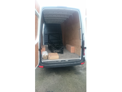
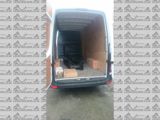
Sprinter4m
And here it is at home ready for unloading.
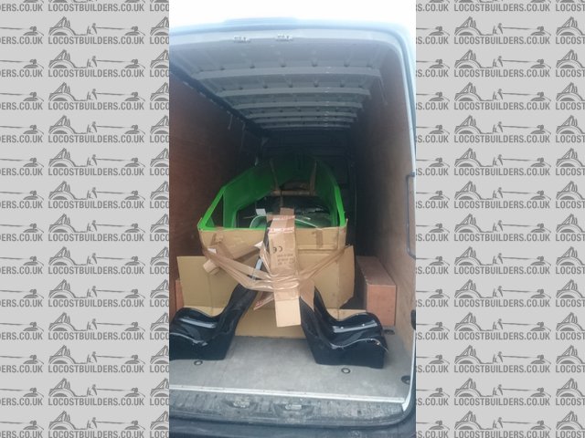
Unloading
Didn't have time to put things away neatly, so very grateful for the oversized garage that came with the house.
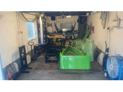
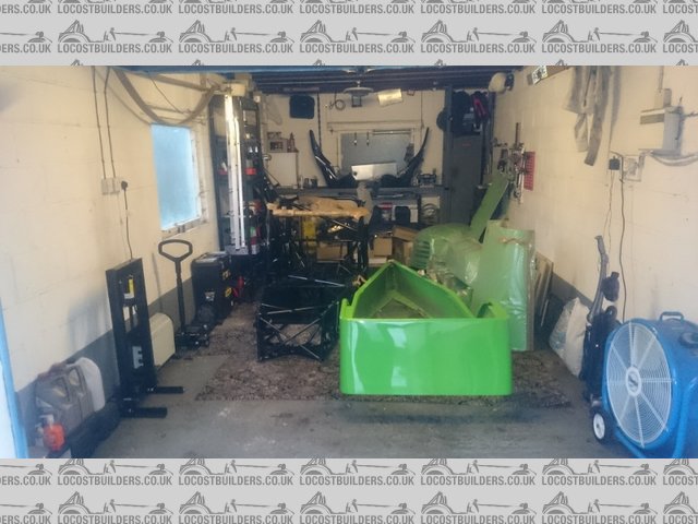
LoadsOfRoom
sdh2903 - 21/12/15 at 06:10 PM
Just check the transmission tunnel is offset......
Nice choice of colour. Now the fun really begins
l5tuy - 21/12/15 at 10:56 PM
The 4.4m van length came in handy for me, I slept in it :-)
Kwan green, good choice. Same as me, interesting as I was told they hadn't done now in years, plenty room for another 2 in the world:-)
I struggled with storage space for the tub, still am if I'm honest.
Good luck.
Stu
DRM Black7 - 21/12/15 at 11:07 PM
Awesome it's great fun picking up the body work etc, I had a 500 mile road trip going to Dj sports cars then on to MK (Martin took me out in
the Demo as well), was an epic day.
Can't wait to see your progress.
prawnabie - 22/12/15 at 07:30 AM
Nice size garage! i built my westie mazda in a single garage - it was of the things that really pissed me off about the build.
micksalt - 22/12/15 at 08:24 AM
quote:
Originally posted by sdh2903
Just check the transmission tunnel is offset......
I'll take a tape measure to it either tonight or tomorrow and check that it is.
quote:
Originally posted by l5tuy
The 4.4m van length came in handy for me, I slept in it :-)
Kwan green, good choice. Same as me, interesting as I was told they hadn't done now in years, plenty room for another 2 in the world:-)
I struggled with storage space for the tub, still am if I'm honest.
Good luck.
Stu
I thought it odd when Chris said that the 4.4 m van was the biggest he'd seen, because I could have sworn someone else had collected using the
same Sprinter. That other person was you of course. The green was actually my wife's choice, and I couldn't be happier with it. I was going
to go for Thomas the Tank Engine blue originally. A friend is building an S2000-powered SR2 in the same green, so that'll be two Yorkshire-based
kits in that colour in North Staffs / South Cheshire. I've got options where to put the tub, there's a big shed behind the garage where it
can go, or I might string it from the roof.
quote:
Originally posted by prawnabie
Nice size garage! i built my westie mazda in a single garage - it was of the things that really pissed me off about the build.
This is a single garage, it's just a very generously proportioned single garage. Not the previous owner of the house, but the one before that, he
used to build, race and maintain go-karts, which explains the big garage and large workshop shed to the rear.
One question for the MNR colective, are the internal panels just glued on? They're not aluminium, so I suspect they would split if I attempted to
rivet them. In fact, I would prefer to keep holes drilled into the chassis to a minimum. Thanks in advance.
theduck - 22/12/15 at 01:00 PM
Mick, this might sound a daft question, but did you used to be a postman?
micksalt - 22/12/15 at 01:10 PM
quote:
Originally posted by theduck
Mick, this might sound a daft question, but did you used to be a postman?
I did not, newspaper boy was about the closest I came. Am I reminding you of someone you once knew?
theduck - 22/12/15 at 06:43 PM
Just knew someone that was once a postie and now lives, I think, in Stoke and is called Mick salt. Close but no cigar.
[Edited on 22/12/15 by theduck]
jim87 - 22/12/15 at 09:42 PM
quote:
One question for the MNR colective, are the internal panels just glued on? They're not aluminium, so I suspect they would split if I attempted to
rivet them. In fact, I would prefer to keep holes drilled into the chassis to a minimum. Thanks in advance.
The plastic the panels are made of it pretty tough. I've no doubt riviting them would be fine. I did what it sounds like you want to do though,
and just glued them on with tiger seal. Slop a load of it on, and it's pretty strong stuff.
micksalt - 24/12/15 at 06:49 PM
quote:
Originally posted by sdh2903
Just check the transmission tunnel is offset
Transmission tunnel was offset, didn't even have to get the tape measure out, it was very obvious.
micksalt - 27/12/15 at 09:58 PM
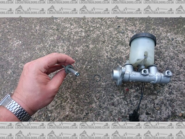
Just rearranging the garage and I've just realised that I shouldn't have given away the brake servo. I now have no means of attaching the
master cylinder to the pedal. Now of course, there is no need for vacuum assistance, so I could just source a replacement servo and block off the
vacuum port, but is there a way of doing it more elegantly, perhaps even removing the servo altogether?
Not to worry, I've figured it out. You use a bolt underneath the pedal to act as a limit stop, and then recycle the push-rod from the old clutch
slave cylinder since the supplied Wilwood clutch cylinder already has a push-rod.
[Edited on 27/12/2015 by micksalt]
sdh2903 - 28/12/15 at 11:58 AM
It'd funny you mention this as I was having the same head scratching moment last week. I've seen a couple of pics of the pedal stop but it
just doesn't rest easy with me that the bolt is a bit of a bodge on the pedal that will save your life. I emailed MNR about it who must be aware
of the issue as Marc is looking at turning up some new pushrods in the new year. Quite how he plans to retain the rod in the cylinder I'm not
sure.
I'm actually 50/50 on ditching the mx5 cyl and buying an aftermarket cylinder with a proper retaining fork and clevis pin.
l5tuy - 28/12/15 at 11:48 PM
I'm planning on disecting the servo in the next few days to reuse the crevice. Interesting to here that MNR are looking to into it, there are
numerous build logs that detail 'solutions' which makes me feel this problem has been reported back to MNR a few times. Think I'll
raise the question, I need to talk to them regarding the clutch reservoir anyway. Chris informed me this was offset to prevent clash with clutch slave
however now it clashes with brake reservoir.
STU
sdh2903 - 29/12/15 at 04:27 PM
Ive had another look at this earlier. Im still not overly happy with the bolt stop in the floor, while i'm sure it would do a job it just
doesn't rest easy with me. Another thought i had was fitting a tether to the pedal maybe a steel cable to add a secondary device to prevent the
pushrod coming out.
Im actually straying towards ditching the mx5 master cylinder altogether as its quite a large bore for a non servo car at 22mm which in theory will
give a softer longer throw pedal and going for a westfield or catering van master cylinder. Maybe westfield dont use the mx5 cylinder in the sdv for a
reason.
Perhaps anyone who has used the mx5 cylinder in a kit could comment on how the brakes feel in the real world?
micksalt - 29/12/15 at 04:32 PM
To be fair, the bolt in the floor pedal stop is used in the Chris Gibbs book, but the pedal has a dedicated nub to engage with the bolt. I think
I'll leave the pedals until I see what Marc has come up with, then I won't have any unnecessary holes in the chassis.
sdh2903 - 29/12/15 at 05:31 PM
Yeah am waiting to see what Marc comes up with, but he did say it would be end of Jan before he mastered his new lathe and am not sure if my
childlike patience will hold.
Anyway I'll stop filling your build thread with my ramblings!!
jim87 - 1/1/16 at 01:04 PM
Yes, will be interesting to see how marc is going to fasten the push rod into the mx5 master cylinder.
Have you see this blog ?
http://fastcraft.biz/blog/?p=856
Its essentially just a pedal stop again, but might give you some ideas
sdh2903 - 1/1/16 at 03:32 PM
Yeah have read that. Ive decided I won't be using the mx5 master cylinder. Its 22mm which is a bit big bore for non servo and will give a bit of
a dead pedal and I'm not comfortable with the bolt in the floor. I've gone for a fiat uno 19mm tandem master cylinder which should give a
better feel pedal. Has a retained push rod and is a brand new item. For the master cylinder, Pushrod and reservoir it's come in at less than 50
quid.
However depending on the next few days I may not need it as I may not carrying on with the build at all, so it might be available if you want it!
micksalt - 1/1/16 at 03:50 PM
quote:
Originally posted by sdh2903
I've gone for a fiat uno 19mm tandem master cylinder which should give a better feel pedal. Has a retained push rod and is a brand new item. For
the master cylinder, Pushrod and reservoir it's come in at less than 50 quid
Can you point me in the direction of where you get these from? All the Uno ones I can find are non-retained. Cheers!
sdh2903 - 1/1/16 at 03:54 PM
I got mine here
eBay Item
Pushrod here
eBay Item
It doesn't physically show the retaining circlip but I've been assured they do have one. I'll soon find out when it arrives in a few
days.
sdh2903 - 1/1/16 at 03:56 PM
Advantage over the fiat 124 one which is popular is that it has standard M10 x 1.0 ports where's the 124 one has oddball coarse M10 x 1.25 ports.
l5tuy - 2/1/16 at 09:24 PM
I'm going standard mx5, couldn't decide on what alternative to use so went with the challenge of utilising the donor part. Bit of cutting
and welding, I'll post pics when I get a chance.
Stu
micksalt - 4/1/16 at 08:08 AM
quote:
Originally posted by sdh2903
I got mine here
eBay Item
Pushrod here
eBay Item
It doesn't physically show the retaining circlip but I've been assured they do have one. I'll soon find out when it arrives in a few
days.
Let me know of the push rod is indeed retained, and what modifications you need to do to the bulkhead (if any). That could be the way I choose to go
too.
Yesterday was a very productive day. I had a bunch of administration work to do for the heritage railway event I'm organising
(shameless plug, but heck, it's a charity). Didn't get out to the car until 14:00 and thought I
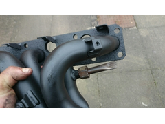
wouldn't get much done. Instead I got the engine, front hub carriers, engine mounts and exhaust manifold sufficiently clean to take paint. Even
found my 1/4" 9 mm socket that had gone missing when I had dropped my toolkit a few days ago The only snag was that I'd positioned the
chassis with the front facing the garage entrance, and the engine and engine crane were behind it. Ended up having to drag the engine along the carpet
to the correct end of the car, Doh!
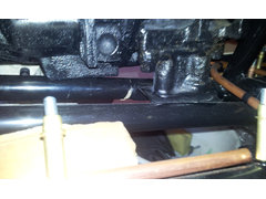
[Edited on 4/1/2016 by micksalt]
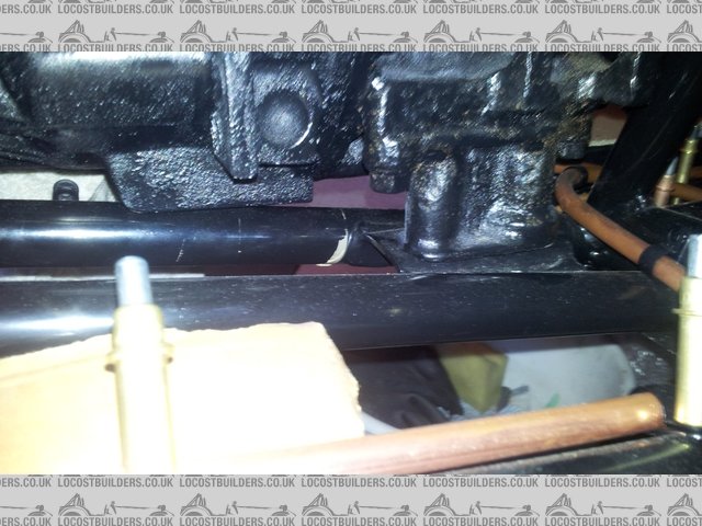
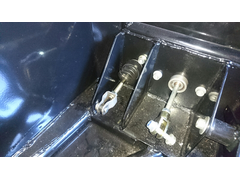
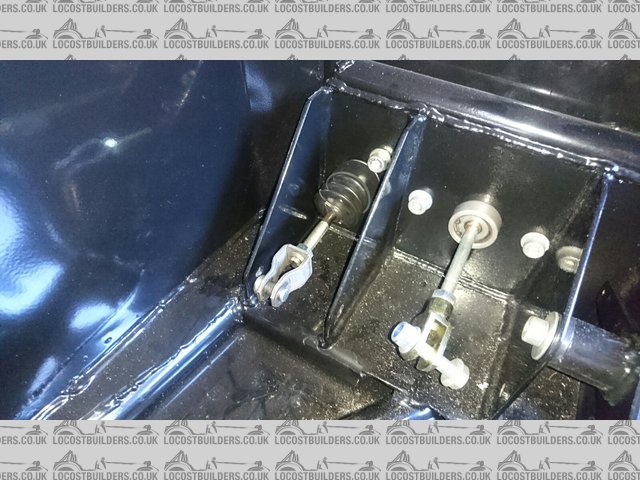
micksalt - 4/1/16 at 06:45 PM
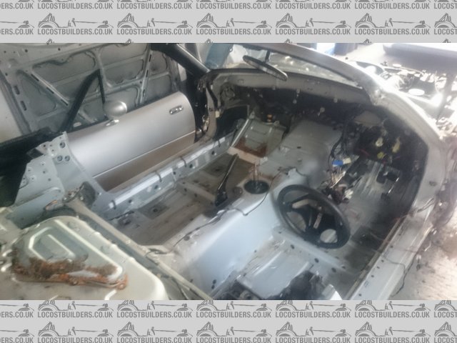
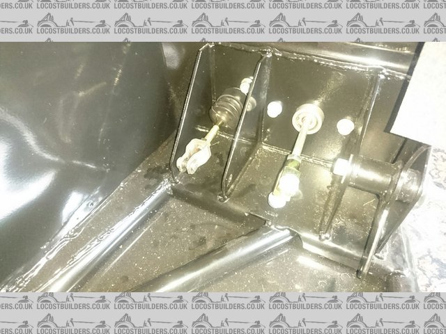
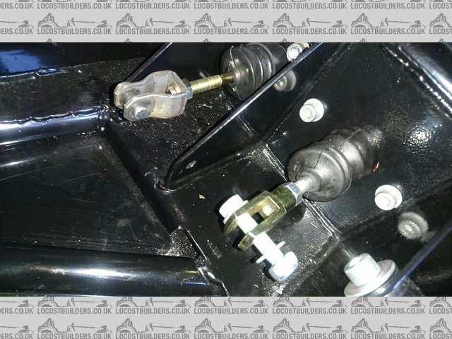
Here's the problem I have, in the original Mazda pedal box that I photographed, the pedal was offset to the left, giving plenty of room to put
the stop-bolt in:

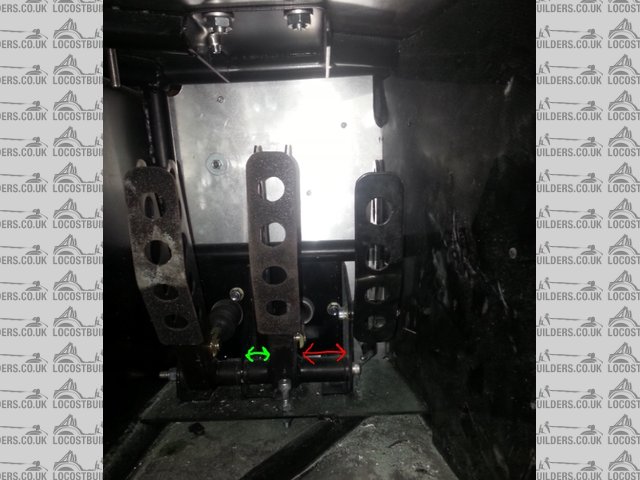
OldMazdaPedalBox
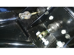
Probably in response to feedback that the brake and clutch master cylinders were too close together, the Mazda brake pedal has been updated to a more
central position. The only problem with this is that the chassis tube now prevents the use of a bolt-stop. I have confirmed with Marc that this is an
updated pedal design rather than a case of the wrong pedal being sent.
NewMazdaPedalBox
I've emailed Marc for advice, but they've got more pressing issues since there's no electricity to the workshop in the moment. I'm
sure a solution will come along shortly, I have every faith, particularly since there's talk of an updated push-rod too
micksalt - 5/1/16 at 11:09 AM
quote:
Originally posted by jim87
http://fastcraft.biz/blog/?p=856
I've just read that properly and I'm not convinced that's a great solution. I can see that pedal stop bending and eventually snapping
with fatigue.
jim87 - 5/1/16 at 11:21 AM
I did think the same actually. If I'd done that, I think I'd try to make it a bit sturdier
Is your pedal box welded to the chassis ? It looks like it is in your pic
micksalt - 5/1/16 at 11:30 AM
It is indeed welded to the chassis. I've noticed quite a few detail changes compared to the car I took reference photos from.
micksalt - 5/1/16 at 09:26 PM
As much fun as the prospect of building a kit car is, what is not so appealing is having to service the daily driver whilst lying in a puddle since
the garage is occupied.
However, having finished with the daily driver (just an oil change this time, nothing exciting), I got distracted by the kit again, specifically how
to seal my steering column top bearing from the elements. And then I had a great moment of
inspiration.
I love this hobby
sdh2903 - 7/1/16 at 04:46 PM
Well as promised. The fiat master cyl has arrived. No retaining circlip. Although I think would be very easy to knock up a retainer as the end of the
pushrod is domed.

Mastcyl
micksalt - 7/1/16 at 07:17 PM
quote:
Originally posted by sdh2903
Well as promised. The fiat master cyl has arrived. No retaining circlip. Although I think would be very easy to knock up a retainer as the end of the
pushrod is domed.
Mastcyl
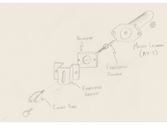
Ah, bad luck, however, easily fixed with a retaining bracket attached to the pedal side of the bulkhead with that particular push rod.

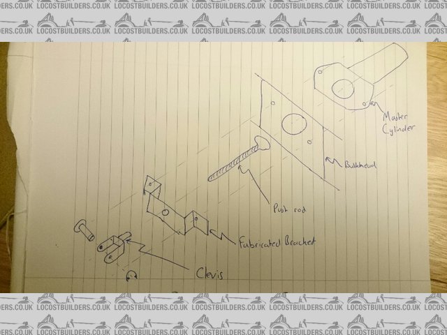
FabricatedBracket
I'll wait to see what Marc has to say before I do anything drastic. If I don't like the solution I may fork out for the Westfield retained
master cylinder.
[Edited on 7/1/2016 by micksalt]
micksalt - 10/1/16 at 08:41 AM
If I had access to a lathe, this would be my solution.
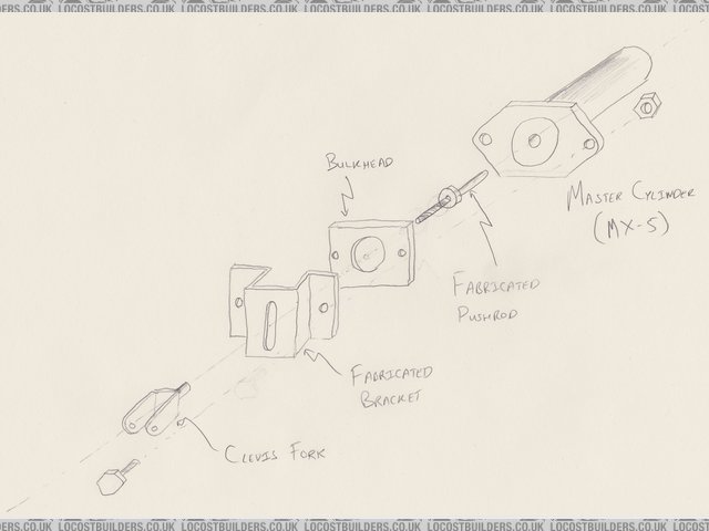
MX5Pushrod
The critical dimension is the radius of the middle section of the pushrod, it should be small enough to enter the body of the pushrod, even accounting
for small angular deflections of the pushrod, but large enough to pass through the slit of the fabricated bracket.
jim87 - 10/1/16 at 07:19 PM
quote:
Originally posted by micksalt
If I had access to a lathe, this would be my solution.
MX5Pushrod
The critical dimension is the radius of the middle section of the pushrod, it should be small enough to enter the body of the pushrod, even accounting
for small angular deflections of the pushrod, but large enough to pass through the slit of the fabricated bracket.
You could just extend the thread on your existing pushrod, and use a nut as the stopper. If the nut is too big then you could grind it down to
size.
I actually ended up buying a small lathe for this kind of thing - not really necessary, but you can make bespoke stuff like this easily
micksalt - 28/1/16 at 08:55 AM
I've contacted MNR to see what is being done to address the pedal issue, and Marc is indeed getting to grips with the new lathe to engineer the
solution. I'd better get cracking, I've had a lazy month....
jim87 - 28/1/16 at 12:13 PM
While you're looking at the pedals, you might want to think about the accelerator pedal.
I've been having a problems with it sticking a little. I think its probably because one the plastic bushings on the pedal isn't quite
square.
I've taken them out now, and am replacing them with aluminium spacers and bearings.
A return spring might help, but that'd be much easier without all the bodywork in place !
micksalt - 29/1/16 at 11:52 AM
Thankfully, I have a box full of bushings and bits donated to me by a friend for fixing his computer should I have problems with the accelerator
pedal.
micksalt - 4/2/16 at 03:25 PM
Please can I ask anyone that has built the Mazda based kit to take a photo of the upper rear suspension where it attaches to the upright? As it
stands, it looks liek the gap in the upper arm is much wider than the top bushing of the upright, and I want to make sure this is correct. It just
seems a little odd for the bushing just to be held into position by the friction-fit into the upright, rather than being backed up by appropriate
spacers each side. Ta in advance
jim87 - 5/2/16 at 10:45 AM
quote:
Originally posted by micksalt
Please can I ask anyone that has built the Mazda based kit to take a photo of the upper rear suspension where it attaches to the upright? As it
stands, it looks liek the gap in the upper arm is much wider than the top bushing of the upright, and I want to make sure this is correct. It just
seems a little odd for the bushing just to be held into position by the friction-fit into the upright, rather than being backed up by appropriate
spacers each side. Ta in advance
I don't have a photo at the moment, but I remember I had to put 3 or 4 washers in between the top upright mount/bush and the bottom damper mount,
to pack it out so that there was no gap.
l5tuy - 5/2/16 at 11:01 AM
Same here bud. Think I used 1 washer between each joint to space everything out which kept it all tight. From memory had to use vice to press
bushings into upright.
1 thing I did notice is the upright and lower diameter of suspension strut had a slight rub.
I'll have photo's, pain in the ass loading them onto here though. Give me an e-mail of Facebook and i'll send you some.
Stu
jim87 - 5/2/16 at 11:10 AM
I needed at least 3 washers in between damper and upright to avoid the rubbing you mention. With 4 in, everything lined up ans was nice and tight.
micksalt - 8/2/16 at 02:18 PM
Cheers folks, I see how it all works now. I'm running out of jobs to do before I'll need the MNR fix for the brake master cylinder. Still,
it'll take a while to order all the other parts I need for the engine and gearbox.
I'll get some pictures up soon with the latest and final painting jobs.
micksalt - 17/3/16 at 08:29 AM
Big order arrived from MX5-Parts yesterday, I'll get cracking again
micksalt - 19/3/16 at 11:25 PM
Whilst working on the car yesterday, I realised that all the EGR delete kits don't block the exhaust manifold end, so you're left with the
weight and engine bay clutter of the connecting pipe. Not any more

RedneckEGRDelete
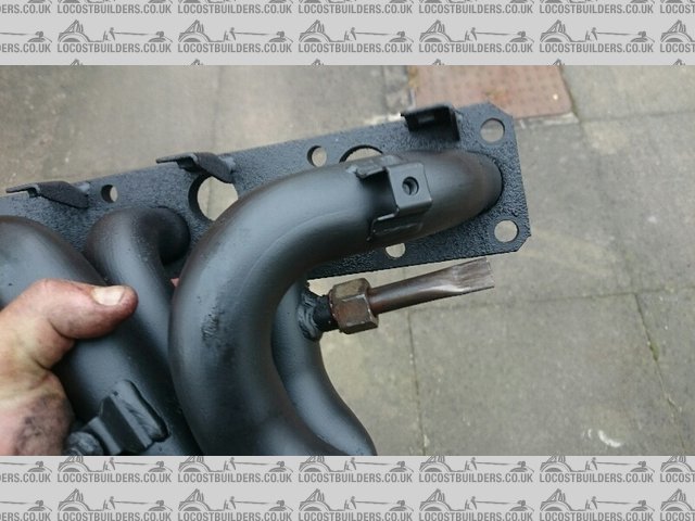
EGRDelete
Anyway, next issue, the O/S flexible brake hose from the MX-5 is permanently joined to a 2-way connector block. How have folk plumbed up their rear
brake hoses? The rear flexi-hoses on an MX-5 are handed, so it's not as if I can order another N/S hose and use that. By the way, all reference I
make to N/S and O/S are relative to the MX-5, I know they swap sides on the Vortx.
Cheers in advance,
Mick
[Edited on 19/3/2016 by micksalt]
micksalt - 20/3/16 at 04:59 PM
Mystery solved thanks to Stu, the flexi hoses should have been included in the kit!
micksalt - 18/4/16 at 11:00 AM
Flexi hoses have now turned up amongst a goodie bag of a fair few other parts. Marc is still getting to grips with his lathe, but is working on the
push-rod fix
micksalt - 22/4/16 at 07:39 AM
A little indulgence on the brake caliper refurbishment:

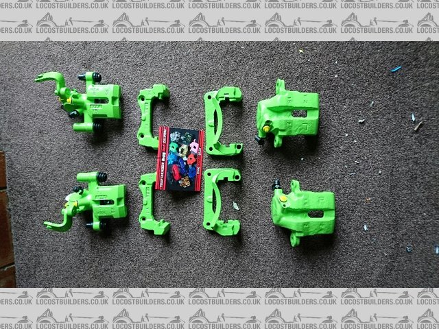
BiggRed
james h - 23/4/16 at 07:50 PM
Hi Mick,
If you don't mind, could you tell me how much you paid Bigg Red for the calipers? My friend's mk1 MX5 has binding brakes at the moment, so
much so that the pads have worn all the way down over 18 months!!
Cheers,
James
micksalt - 23/4/16 at 08:11 PM
�296 including new slider pins and return postage. I think the outbound postage was about �16, so �312 all in for all four calipers.
james h - 23/4/16 at 08:27 PM
quote:
Originally posted by micksalt
�296 including new slider pins and return postage. I think the outbound postage was about �16, so �312 all in for all four calipers.
Thanks
I just rang my friend, turns out she's bought some none OEM replacements anyway!
[Edited on 23/4/16 by james h]
micksalt - 23/5/16 at 06:07 PM
PUBLIC DECLARATION: I am a muppet.
I fired Marc an email to find out where he was up to with the new retained pushrod design. The response I got that he had already sent me the
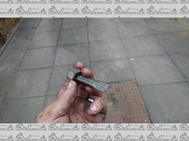
prototype, and then the penny dropped, the curious looking bolt I received in addition to all my other parts WAS the push rod modification, intended
to be retained by the original master cylinder circlip.

Push Rod
Two minutes with a pair of circlip pliers, and the problem was solved

Master Cylinder
Now I've got the big event at the railway out of the way, I can get properly cracking.
sdh2903 - 23/5/16 at 06:32 PM
Get cracking? Thought you'd have finished by now!
micksalt - 23/5/16 at 06:57 PM
quote:
Originally posted by sdh2903
Get cracking? Thought you'd have finished by now!
I wish, too busy sorting this event out http://www.ww1-event.org
[Edited on 23/5/2016 by micksalt]
micksalt - 26/5/16 at 10:34 AM
*** EDIT: the push rod fix DOES work, please see my follow-up thread ***
Bummer, the MNR push-rod fix doesn't work. It seemed like an elegant solution in principle, but the washer and push rod hold the master cylinder
too far in for the inlet ports to be exposed, so there's no way to get fluid into the system. A little bit disappointed if I'm honest, I
expected something more like my proposal after waiting months
MX5Pushrod
[Edited on 28/5/2016 by micksalt]
sdh2903 - 26/5/16 at 12:45 PM
I'd just bin off the std mx5 unit anyway. You'll get a much better feel from a smaller bore cylinder that's designed for non servo
applications anyway.
jim87 - 26/5/16 at 12:46 PM
quote:
Originally posted by micksalt
Bummer, the MNR push-rod fix doesn't work. It seemed like an elegant solution in principle, but the washer and push rod hold the master cylinder
too far in for the inlet ports to be exposed, so there's no way to get fluid into the system. A little bit disappointed if I'm honest, I
expected something more like my proposal after waiting months
MX5Pushrod
Maybe you could shave a few mm off the piston to make space for the washer ? Seem to remember there's plenty of meat on the piston, but I dunno
whether it's a good idea on important brake parts ?
micksalt - 26/5/16 at 02:22 PM
*** EDIT: the push rod fix DOES work, please see my follow-up thread ***
I'm thinking that I might just go for the Westfield
Option.
[Edited on 28/5/2016 by micksalt]
micksalt - 28/5/16 at 10:30 AM
Well, this is embarrassing, the push rod fix DOES work . I was trying to pull fluid through using a vacuum pump and pipe directly against the
cylinder outlets, but then I thought I'd better test what happens with the push-rod fix NOT installed and I got the same result. I dug around in
my box of tricks and found a better rubber connector to connect to the outlets and sure enough, fresh fluid at all the outlets. Put the push rod fix
back on, and again, fresh fluid. I angled the push rod to quite a severe angle since this pushes the cylinder in slightly, and I still get fresh
fluid.
Apologies to anyone I mislead with my flawed testing
micksalt - 9/7/16 at 11:45 AM
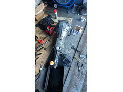
Finally finished with the restoration of the oily bits.
First of all, started with a proper scrub of the gearbox.
CleanGear
Fitted a new clutch release bearing, clutch release arm, gaiter, slave cylinder, turret seal and turret oil. Made the mistake of filling the gearbox
with oil, not realising that the seal relies on the driveshaft being inserted. Ended up with a very messy floor when I tilted the gearbox to put it
back on the engine.
SlaveCylinder
After that mishap, engine and gearbox came together for the first time in a long while.
SlaveCylinder
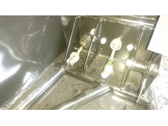
I've moved onto the actual kit itself now. Installed both master cylinders including the clevis pin assembly. Curiously, the brake master
cylinder is centred on the pedal, rather than centred on one of its vertical sections. This means that the clevis pin ends up between the two vertical
plates of the pedal, and you need a longer clevis pin to accommodate it. I'll post details when I install the pedals.
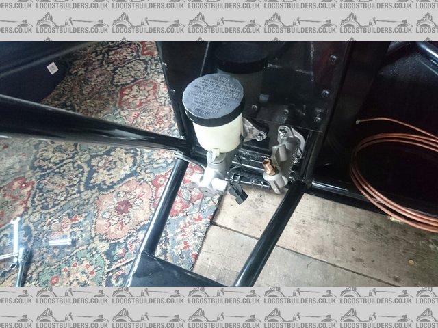
MasterCylinders
ClevisPins
Also trial-fitted the T-pieces required for the braking system. MNR fit a small tab to the chassis to hold this, which is a very nice touch.
TPiece
The brake hoses themselves have got me rather confused. To the left of my tape measure are the pipes that connect to the flexi-hoses, evidenced by the
fact they have the female connections on one end. What puzzles me about these though is that one is a very different length to the other. The T-piece
sits roughly in the middle of the chassis, and the chassis is symmetrical between the T-piece and the flexi-hose attachment points, so there seems to
be no reason that just one is much longer.
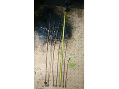
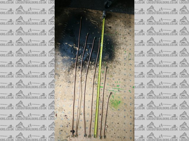
RigidToFlexi
Also, I assumed that the very shortest pipe was to connect between the clutch master and slave cylinders. By a process of elimination, the pipe I am
holding here is the one to connect the master cylinder to the T-piece, and as you can see, it is desperately short. Did anyone else have similar
issues?
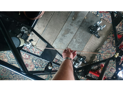
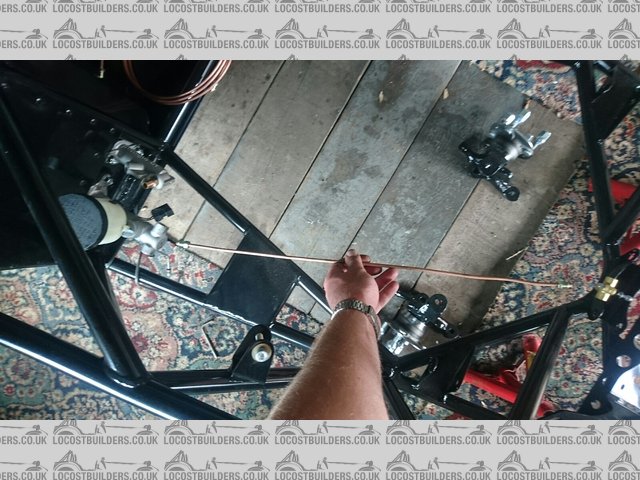
TooShort
Cheers,
Mick
sdh2903 - 9/7/16 at 03:33 PM
To be perfectly blunt the best thing you can do with the mnr supplied brake pipes is chuck em in the bin. The lengths really didn't correspond to
where they were supposed to go. In my case they were all way too long. They are also made out of copper which will eventually work harden. I ended up
recycling all of the fittings and made my own pipes to the correct lengths using 3/16 kunifer pipe. Bit of a pain but better in the long run to use
kunifer.
micksalt - 9/7/16 at 03:43 PM
quote:
Originally posted by sdh2903
To be perfectly blunt the best thing you can do with the mnr supplied brake pipes is chuck em in the bin. The lengths really didn't correspond to
where they were supposed to go. In my case they were all way too long. They are also made out of copper which will eventually work harden. I ended up
recycling all of the fittings and made my own pipes to the correct lengths using 3/16 kunifer pipe. Bit of a pain but better in the long run to use
kunifer.
Sounds like a plan.
micksalt - 9/7/16 at 04:07 PM
Any recommendations on a good flaring tool? I assume we're double-flaring with it being brakes.
sdh2903 - 9/7/16 at 04:28 PM
Some are double flared, from memory into the bias valve and the bulkhead ends where the flexys connect.
I've had good success after a bit of practice with the laser hand held tool in the link below (you will get cheaper on ebay). The bench mounted
ones are better but more expensive. I've done a couple of cars worth with the hand held one with no leaks. Keep the copper pipe to make templates
as the kunifer is a bit harder to bend in situ. Also keep some to practice the flares. Might be worth also buying a pipe bender too.
https://www.machinemart.co.uk/p/laser-pipe-flaring-tool/
micksalt - 10/7/16 at 04:19 PM
I wasn't intending to work on the car today, but got a bit carried away. I was a bit dubious about the fit of the steering column and associated
joints, so I thought I would do a trial assembly. After a bit of wriggling, it all seems to fit very nicely indeed.
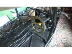
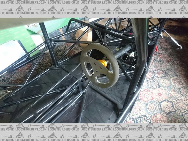
InstalledColumn
Detail of the column mounts.
ColumnMountDetail
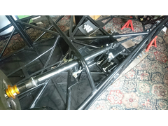
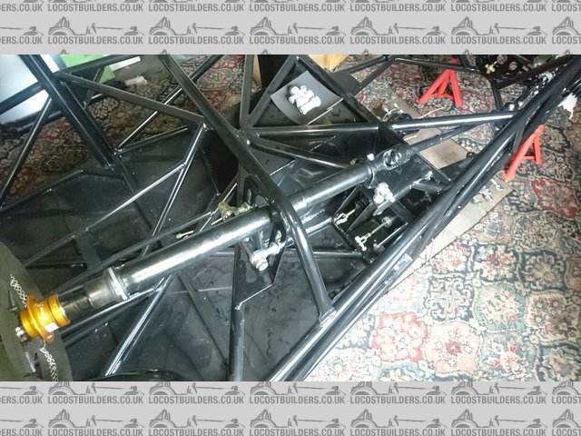
Detail of the bracket / bushing on the intermediate shaft. I'm not 100% on there being a plastic bushing with the column and rack having
ball-bearings. I might be slipping beer tokens to my tamed machinist to have something made with proper bearings and a metal body.
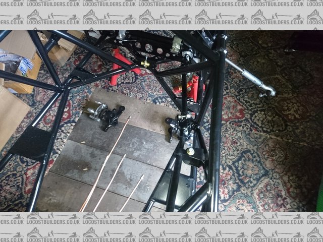
MidSupportBracket
After doing some research on the IVA requirements for the fog light switch, it either required some ingenuity, or about �60 worth of electronics to
comply. Instead, this from a mk4 VW Golf seems to do everything I need using a mechanical interlock. I've tested it against the Golf wiring
diagram and it performs as expected, and will give a bit of 'production car' feel to the dashboard. The best part is that it was a mere
�4.75 (Part number 1C0941531), although you don't always get the wiring plug, which is very useful to have, particularly that the wiring diagrams
reference the plug numbers, not the pin numbers on the switch.
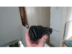
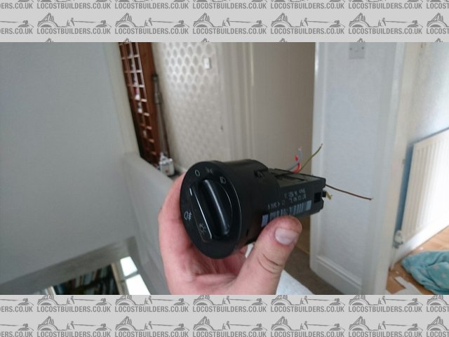
FogSwitch
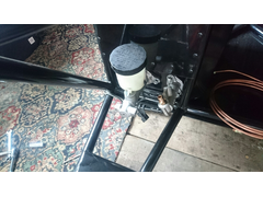
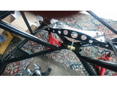
Since I'm making my own brake pipes, I am thinking of a departure from the default MNR layout. In the MNR layout, the brake pressure switch is
mounted underneath the proportioning valve. However, with the proportioning valve located above the height of the master cylinder reservoir, this
means that the switch needs to be removed to bleed the circuit - far from ideal.
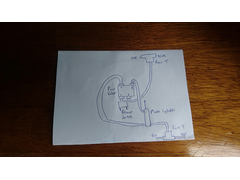
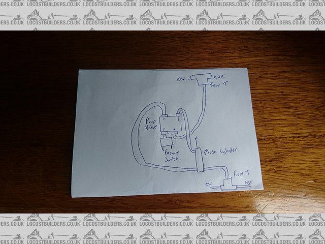
DefaultBrakePipes
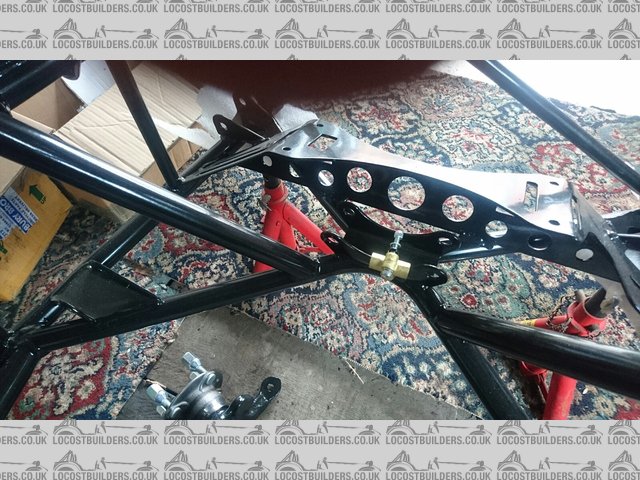
My proposed improvement is to mount the pressure switch directly off the master cylinder, below the reservoir height. By connecting the front brakes
via the proportioning valve, all routes through the proportioning valve end up at the caliper, where there is a bleed valve to pull any air through,
rather than dead-ends. Does anyone see any potential problems with this setup?
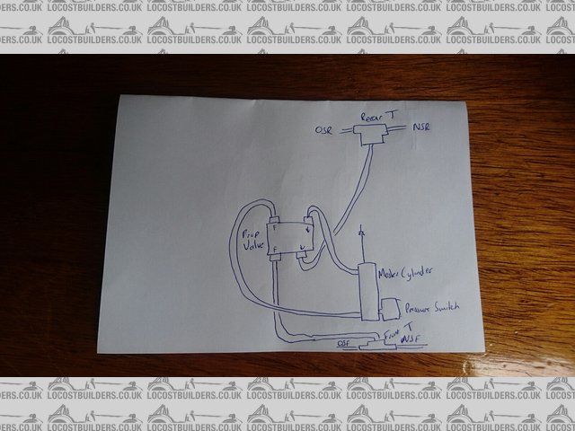
ProposedBrakePipes
Cheers,
Mick
[Edited on 10/7/2016 by micksalt]
sdh2903 - 10/7/16 at 05:34 PM
Ref the switch. I had it in the master cylinder as per your suggestion. I've seen a few other builds with it there too. Best place for it in my
opinion.
micksalt - 11/7/16 at 06:52 PM
quote:
Originally posted by sdh2903
Ref the switch. I had it in the master cylinder as per your suggestion. I've seen a few other builds with it there too. Best place for it in my
opinion.
Excellent, that's the way I shall go then.
micksalt - 14/7/16 at 05:30 PM
Lots of presents turned up today up today including all the tools for making my brake pipes. However, not a lot of time today so I just fitted the one
part.
BareMaster
Gaiter
Available from Demon Tweeks, cost me less than a fiver.
ClothedMaster
I had read about a fellow Locostbuilder that got a stone caught in the master cylinder causing the brakes to bind, so i would recommend this.
jim87 - 14/7/16 at 07:04 PM
I originally had the pressure switch at the front, in the 3 way t piece, but changed it to the way you're going to.
You can make the MNR supplied pipes work, I think this is much neater
micksalt - 14/7/16 at 08:01 PM
My issue with the MNR pipes were that the feed pipe to the front T piece was way too short. For the sake of a tenner's worth of kunifer pipe and
some tools I'll get to use again and again, I may as well make to measure.
micksalt - 15/7/16 at 05:19 PM
Before I commit to drilling holes and forming the kunifer pipe, please can folk take a look at the rough routing I've mocked up with the original
copper pipes and tell me if it looks right.
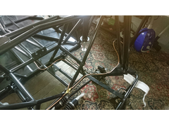
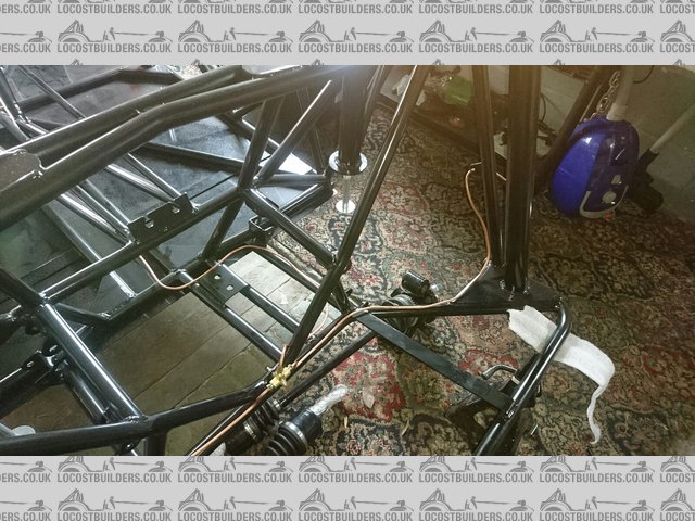
RearBrakePipes
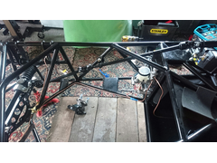
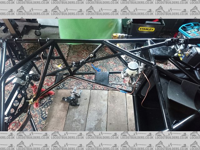
FrontFeed
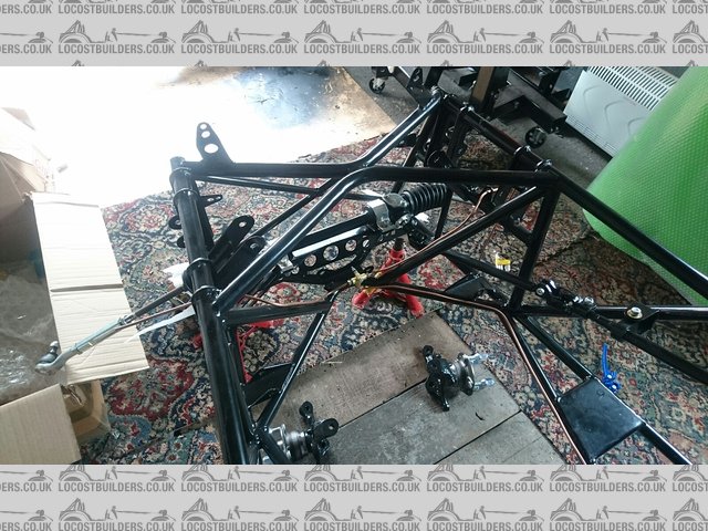
FrontPipes
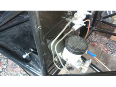
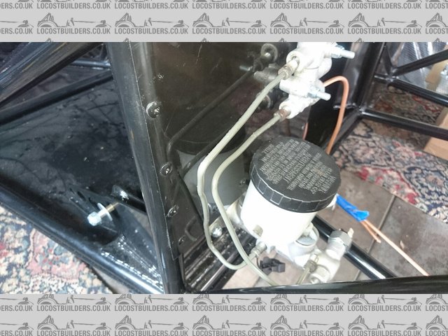
BiasValve
micksalt - 19/7/16 at 10:31 AM
Looks like I'll be making up my kunifer pipes to this pattern then this Friday. I'm going to get myself a nicer pipe cutter though, I'm
still nursing the blisters from Friday
jim87 - 20/7/16 at 06:39 PM
Looks very similar to the way I have mine.
Just be careful where you route around where the clutch slave cylinder will be. The clutch fork gets within an inch ish of the chassis tube when fully
disengaged
micksalt - 20/7/16 at 07:03 PM
Cheers Jim, I'll try to keep the vertical hoses as far too the offside as I can get them.
micksalt - 26/7/16 at 08:35 AM
First of all, this tool was an absolute joy to use. I had never made a pipe flare in my life, and yet using this tool, I did a whole car's worth
without a single bum flare.
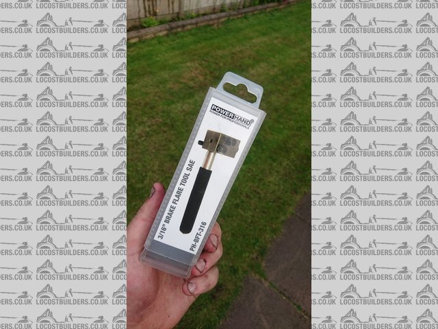
Powerhand
And here is the first pipe, double-flared at both ends this time.
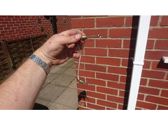
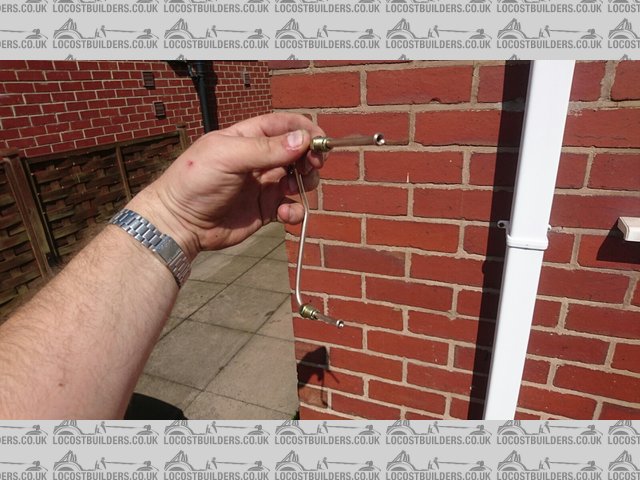
FirstPipe
I decided that because the diff sits quite high, the best route for T-piece feed was this way. It was double-flared at the bias valve end,
bubble-flared at this end to match the T-piece.
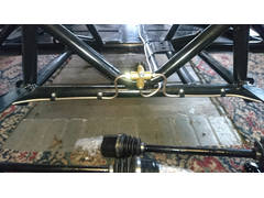
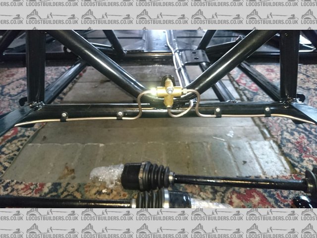
RearT
And to the rear flexis. I think I need to neaten this up to make sure that there is less than 6 inches of unsupported pipe. This was bubble-flared at
the T-piece end, double-flared at the flexi end to match the profile.
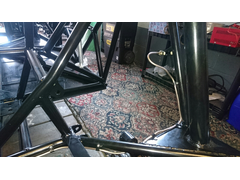
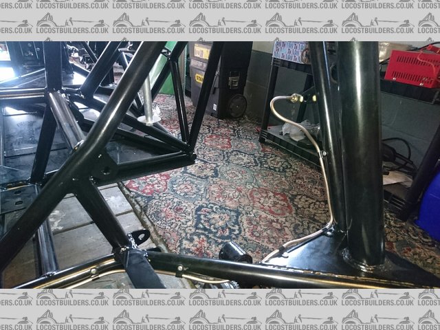
RearBrakePipesFixed
Very chuffed with the plumbing around the master cylinder and bias valve.
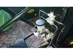
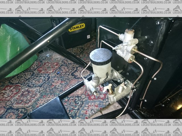
BiasValvePlumbed
And to the front flexis. Remember, bubble-flare at the T-piece, double at the flexi.
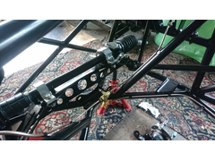
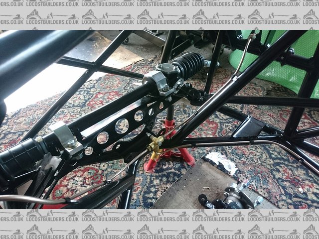
FrontPipesFixed
I didn't take a picture of this, but I had enough kunifer left over to make a generous length of clutch pipe. I had forgotten to note what style
fitting was at the Wilwood master cylinder end, so had to take it off to check. Turns out it is bubble flare at the master cylinder, double flare at
the slave. The reason I have made this longer than necessary is to put a loop in like the original MX-5 pipe to ensure that the pipe can accommodate
relative gearbox to chassis movement.
l5tuy - 27/7/16 at 10:59 AM
Very nice Mick.
Where did you buy the flare tool? Is it a hand one or vice?
Stu
micksalt - 27/7/16 at 11:05 AM
It's a hand-held one, although I suppose there's nothing to stop you slipping off the neoprene sheath and clamping it in a vice if required.
I got it from Brake Pipe Flaring Tool Powerhand PH-BFT-316 3/16". It's by a company called Powerhand, and made in
England, so you'll be doing your bit to prop up the economy
[Edited on 27/7/2016 by micksalt]
micksalt - 3/8/16 at 08:02 AM
Sorry for the lack of updates folks, ended up giving myself sciatica by sitting on the garage floor for too long. Did a stint volunteering at the
local heritage railway instead which seems to have sorted my back out. Should be installing fuel pipes and fitting the pedals to their cylinders this
weekend. I've found a guide for fitting the pedals to make sure it is optimised for hee-and-toe, but at 6'3" tall I might optimise the
pedal positions for leg length as the priority.
micksalt - 8/8/16 at 07:43 AM
Before I do anything daft...

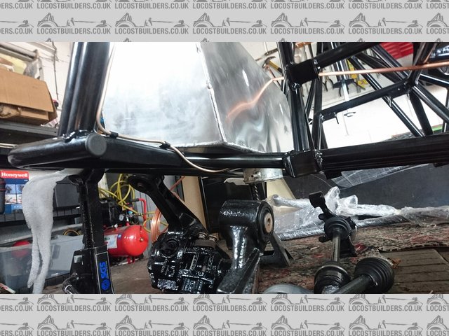
FuelPumpSide
In the build manual, the fuel pump is mounted on the nearside, on the chassis turb that carries the rear lower suspension brackets. However, looking
at my fuel tank, the outlet is pointing towards the offside, suggesting that the fuel pump should also be mounted offside. Please can fellow MX-5
based builders confirm? Any pictures of this area would be greatly appreciated.
Also, how does the fuel pump attach to the hoses? At the pump inlet end, it seems that I need a 10 mm bayonet to M18 thread adapter for connecting the
rubber hose between the fuel tank and the pump, which seems easy enough. However, the outlet end of the pump has a very strange fitting, the same as
this pump from CBS. I assumed that I just attached a small length of
rubber hose between this outlet and the end of the copper fuel pipe. However, this outlet has weird holes around the stem. Is there a specialist
adapter I should be aware of?
Cheers,
Mick
[Edited on 8/8/2016 by micksalt]
40inches - 8/8/16 at 08:04 AM
The pump uses a banjo fitting. I got one of eBay for about �5.
Best photo I have, but I think you can see it OK?
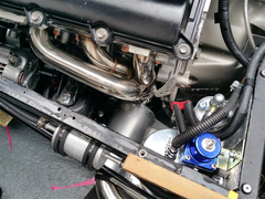

Description
micksalt - 8/8/16 at 08:16 AM
Thank you very much, I see it now, I need a 12 mm banjo, copper washers and cap nut similar to
this, but probably cheaper from eBay (I need to check my fuel hose ID. Very
good.
Actually, I'm struggling to find the inlet end now, I thought that an M18x1.5 male thread to 6/8 mm ID hose tail would be reasonably common, but
my searches are drawing a blank
micksalt - 8/8/16 at 08:39 AM
My search for 'Bosch 044 adapters' was far more fruitful. Going to check with MNR first though to see if they should have been included with
my kit, particularly since I am missing the fuel pump bracket too.
40inches - 8/8/16 at 10:04 AM
I have one or these spare Fuel pump bracket, if
it's any use to you?
micksalt - 8/8/16 at 10:11 AM
Cheers 40inches, unfortunately, it's supposed to be one that is mounted from one side only, more like a giant 'P' clip. This is
supposed to be a comprehensive 'just add MX-5' SDV kit, so I suspect it has just been missed as part of my kit.
40inches - 8/8/16 at 10:30 AM
Ah! got you, the same as the filter mountings in my photo?
micksalt - 8/8/16 at 10:45 AM
quote:
Originally posted by 40inches
Ah! got you, the same as the filter mountings in my photo?
That's right, yes. Thank you very much for all your help
micksalt - 12/9/16 at 10:11 AM
Really slow progress at the moment, got a few DIY tasks at home to deal with. Quick question, attaching the fuel pump to the chassis, rivet or rivnut?
Rocket_Rabbit - 12/9/16 at 04:05 PM
Aren't you using the OEM Mazda pump? If so, it should be internal to the tank? Or are you using some sort of lift pump arrangement?
micksalt - 12/9/16 at 04:09 PM
It's a brand new Bosch 044 type pump. MNR didn't reuse the MX-5 pump and supply a seperate pump and fuel level float instead.
sdh2903 - 12/9/16 at 04:15 PM
Rivnut and use 2 rubber lined p clips.
micksalt - 12/9/16 at 04:24 PM
quote:
Originally posted by sdh2903
Rivnut and use 2 rubber lined p clips.
I suspected one clip was a bit light. I ordered five as a matter of course. Ta very much, rivnut it is then.
jim87 - 13/9/16 at 04:29 PM
Used a rivnut on mine, and no problems in 3000 miles so far. Not come loose or anything
micksalt - 4/10/16 at 08:47 PM
Well, it all became more obvious one I trial-fitted. The fuel pump does indeed go on the side shown in the manual. Once I laid it all out, I realised
it was the only way that the pre-pump filter fitted properly.
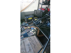
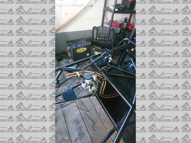
FuelFront
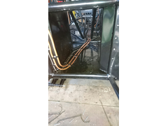
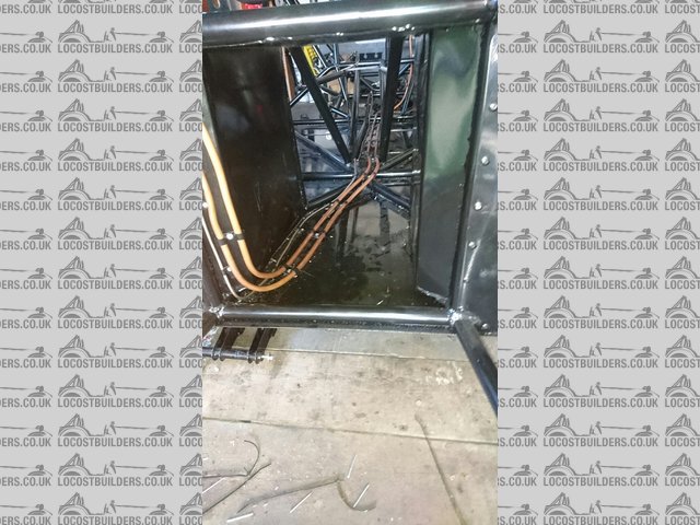
FuelTunnel
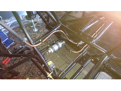
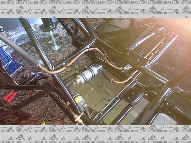
FuelPump
The rivnuts for the fuel pump proved interesting, The instructions for the tool explained how to install the rivnut, not how to remove the tool. Had a
tool stuck to my chassis for a while whilst I figured out how it actually came off.
l5tuy - 4/10/16 at 09:15 PM
Looking good buddy.
Quick point, your brake pipes seem to run over the gearbox mount point in the centre tunnel? I had to stack mine vertically at the side of the mount
plate.
Cheers
Stu
micksalt - 5/10/16 at 08:41 AM
I had forgotten to check where the gearbox mount point goes. Should hopefully be enough flex for me to mount them vertically as you suggest. Thanks
for the heads-up.
micksalt - 8/10/16 at 07:07 PM
Does anyone have a picture of the rear gearbox mount in place so I can figure out how far I need to move the pipes out of the way?
jim87 - 8/10/16 at 07:36 PM

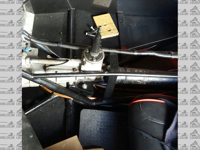
Descgb
micksalt - 9/10/16 at 04:07 PM
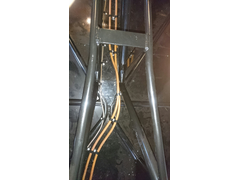
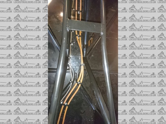
FuelPipeReRoute
Thanks Stu and Jim, that could have been a lot of rework without your help.
l5tuy - 9/10/16 at 08:35 PM
No bother, looking good now.
You on facebook? There is a cracking owners page there, sadly I only recently found it and I'm about 90% done. Still been helpful though.
Stu
micksalt - 9/10/16 at 09:00 PM
I am on Facebook, but didn't know about the owner's club. I've just joined.
micksalt - 17/1/17 at 12:38 PM
Any recommendations for self-tappers to use to mount the fuel sender unit in the tank?
cjwood23 - 24/3/17 at 11:04 AM
Lovely looking build so far!
micksalt - 24/3/17 at 11:08 AM
Thank you very much indeed. I'm trying to get back into the project but my newborn daughter comes first. Turns out I'm more productive in
the bedroom than the garage these days
cjwood23 - 24/3/17 at 11:38 AM
quote:
Originally posted by micksalt
Thank you very much indeed. I'm trying to get back into the project but my newborn daughter comes first. Turns out I'm more productive in
the bedroom than the garage these days
Kids have that effect!
Enjoy them while they're young though - they really do grow up fast!
micksalt - 28/3/17 at 03:21 PM
Been ages since an update.
First up was the fuel level sender, which was a bit long for the tank. Whilst this soldering isn't pretty, I've given it a good bash and a
pull to make sure it was solid.
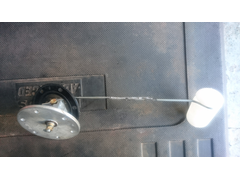
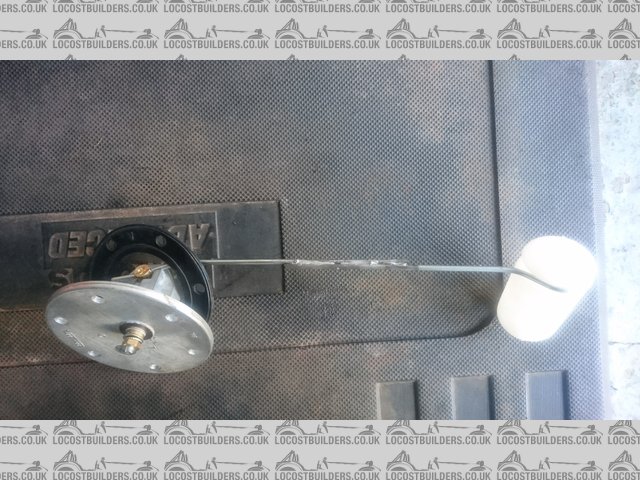
SolderLevel
Next up was to cut a hole in the tank. I had the worst hole-saw that pretty much ground the hole out rather than cutting it. Thankfully, it
didn't have to be too precise.
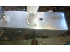
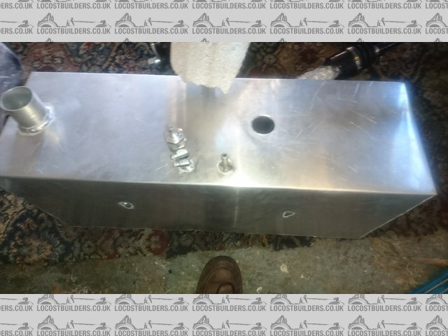
RoughHoleSaw
And it fits! I connected up my multimeter and turned the tank upside down to check that I had the full movement range.
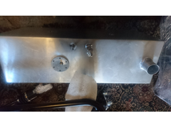
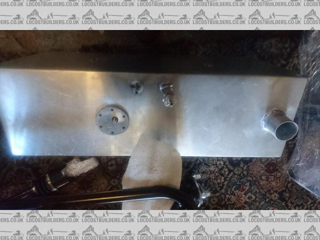
SenderInstalled
But then, it was a case of rain stopping play, although it was oil, not rain. A friend brought her car in wondering why she was having to top it up by
several litres a week. It hadn't had an oil and filter change in 30,000 miles and the filter had rusted through. In fact, the filter fell to
pieces under my strap wrench, which could have been a disaster.
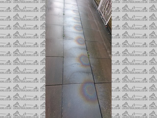
DripDrip
After that, I made up my tank straps, but then realised that my fuel return hose was a bit short, so called it a day. Once the tank is in, I can make
a start on the body, then see about putting the suspension and wheels on so at least I can move it about a bit.
Mash - 21/6/17 at 06:48 PM
You haven't been on for a while Mate, but you're doing a great job.
Hope you don't mind me asking how you fixed the sender unit in your tank as mine has no hole so I'm going to have to cut one and fix the
sender in somehow
micksalt - 21/6/17 at 08:32 PM
I'm hiding in shame after slightly cracking the body tub when moving it . On the plus side, it is nowhere visible and it also made me pause and
remember that I needed to fit the scuttle panel first, which could have been an embarrassing mistake. I'll just get a fibreglass repair kit and
reinforce the back of the split to prevent any further damage.
As for mounting the sender unit. I used these from Screwfix:
http://www.screwfix.com/p/carbon-steel-self-drilling-screws-4-8-x-16mm-100-pack/68505
And I figured out that the rubber seal between the sender unit and the tank doesn't actually prevent vapours from coming up past the screw, so I
put a 5 mm copper washer under each one to seal it against the sender unit body. With them being self-tapping, the screw should seal against the soft
aluminium of the tank, but I wanted to be doubly sure.
Mash - 21/6/17 at 08:40 PM
Thanks Mate, they look just the job
micksalt - 21/6/17 at 08:43 PM
I was worried that those ones were a bit short at first, but they had plenty of bite into the tank.
micksalt - 18/9/17 at 11:17 AM
Got the family coming to visit this Saturday to help to mount the body tub. After that, progress should speed up again because most of it is just
bolting things together. I think I am going to wimp out of building my own engine loom and just get Canems to do that for me. By the time I've
purchased all the materials to do it, the difference in cost won't be that different. I will still have to build my body electrical systems loom
though
super-ron - 18/9/17 at 08:06 PM
cant wait to see the body on!
[Edited on 18/9/17 by super-ron]
micksalt - 18/9/17 at 08:55 PM
Scuttle panel is now in place, and after a tip from the MNR Owner's Club, I will be gluing the internal carbon effect panels before lifting the
bodywork into place.
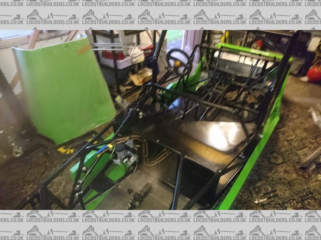
BodyToFit
Not a lot I can do until the bodywork is in place, so I just fitted the rockers. Really nice piece of kit these, not just having radial-load needle
rollers, but also axial load needle rollers too!
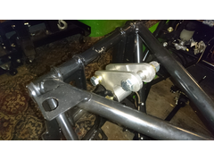
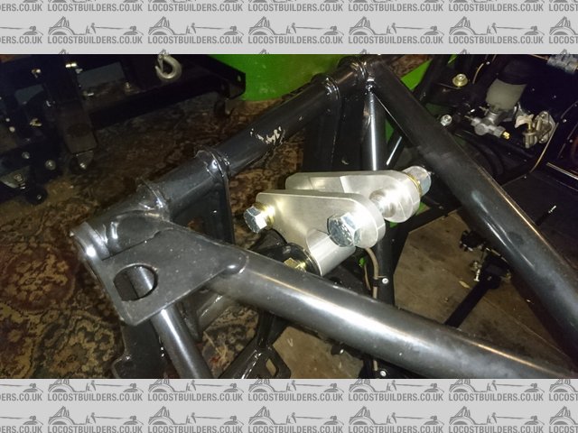
Rocker
Of course, once the bodywork is on, I can cut the holes for the front suspension, build up the suspension both back and front and get it onto its
wheels. Not before time either, I'll need to evict the car for a day whilst doing a major service on the daily driver, which is due in just 5,000
miles time.
micksalt - 13/12/17 at 09:57 PM
Do you know what annoys me?
Incomplete blogs, and I was almost guilty of this myself, so I've decided to put some time aside to get this one up to date
Having had my mishaps with the main bodytub, I decided to wait until I had some help available. Of course, to line everything up, I needed to cut the
scuttle panel for the steering column and cut a little bit off its base where the dash rail joins to the main top chassis rails. I also mounted the
internal panels using Tiger Seal, which were thankfully thin enough to cut with sturdy scissors where adjustment was necessary. If you have the full
cage like me, you need to cut the side panels down the middle and mount separately.
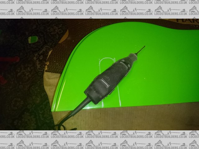
ScuttleCut
After the help of family to mount the main tub, I trial-fit the scuttle into position. It needed a little fettling to one side because I'd
obviously got a slight misalignment whilst trial fitting.
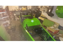
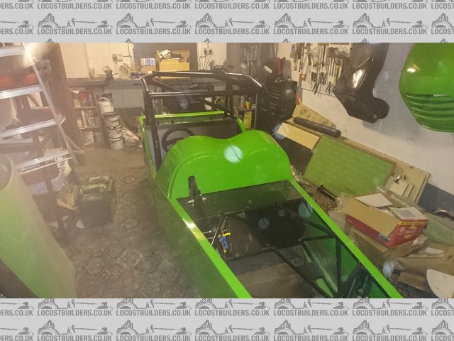
ScuttleTrial
And the rest of the bodywork got a trial fit to ensure the main tub was properly aligned.
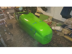
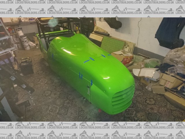
FullTrial
Finally, I could fix the main tub. I took Leon's advice and glued it using Tiger Seal. Bit of a pain to remove if I need to, but it saves
drilling any extra holes in the chassis.
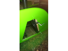
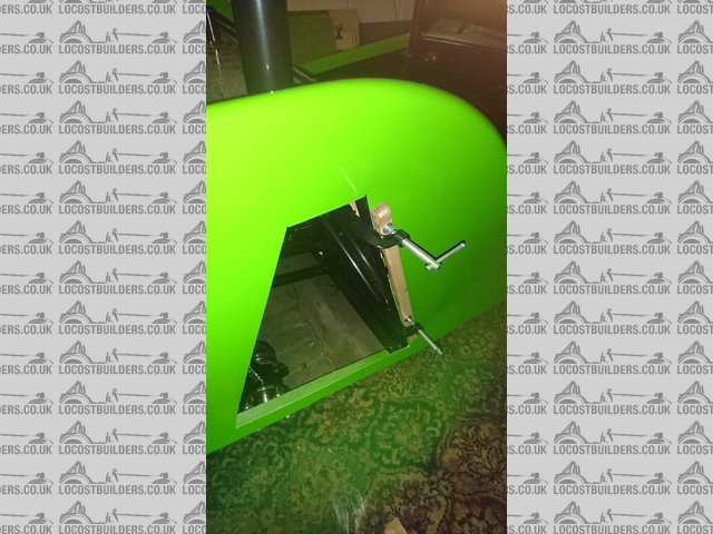
TigerSeal
After some discussion and disagreement on the MNR owner's Facebook page as to which way the front top wishbones were to be mounted, I contacted
Marc himself. This resulted in this annotated picture back from him. Notice that the slight angle of the tube that holds the rose joint points upwards
on the outside. Despite knowing this, I did mount the offside one upside down on the first attempt having got distracted looking for a tool.
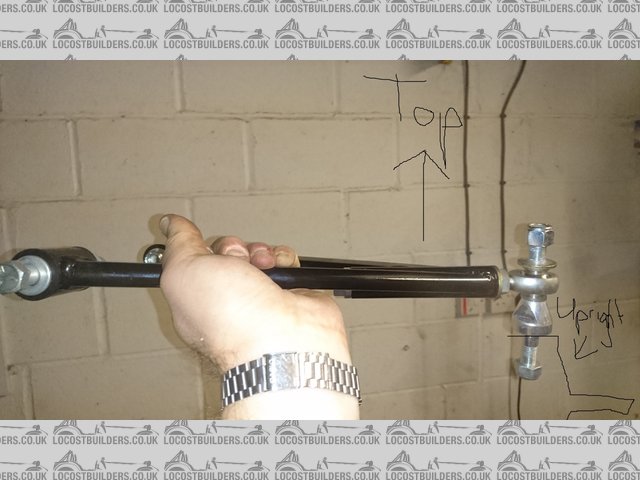
ThisWayUp
To cut the holes, I used a hole saw in the approximate location of the suspension mounts, fettled with a Dremel to get an initial fit of the
suspension arms, fitted the arms, then fettled to give it its full travel. I wouldn't actually recommend this technique since it resulted in
holes being larger than necessary. If I had my time again, I would temporarily mount the suspension before mounting the main tub, create a cardboard
template to give the desired clearances, remove the suspension, mount the main tub, then tape the template to the tub and cut the holes accordingly.
You can always find a new piece of cardboard if you screw up, you cannot uncut a hole in GRP. It's also a very messy, dusty job.
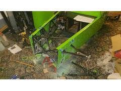
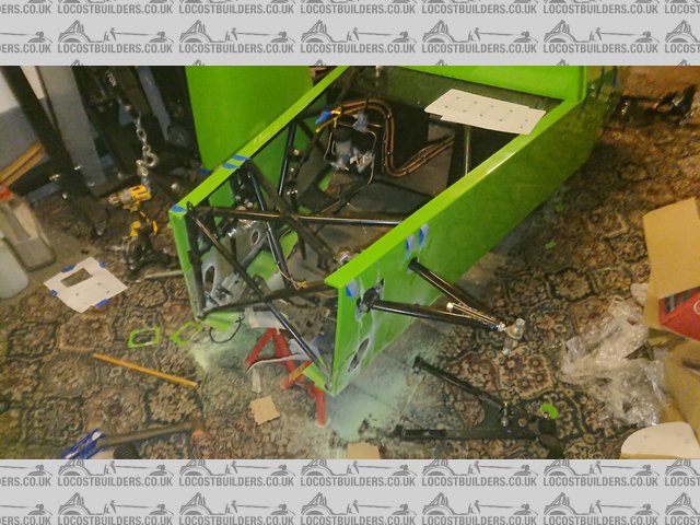
FrontDust
At this point, attention turned to building up the rear suspension. Top-tip, when you push the driveshafts into the diff, do check that you've
not threaded it through the top suspension arm. Cost myself 15 minutes correcting this mistake. You'll see at this point that the lower
suspension arm is not yet fitted. This is because the top-hat spacers supplied with the arms were a tiny bit too big for the MX-5 hub carrier. If I
had a mini lathe, I would have turned them down a bit, but I did not, so I had to resort to a file and elbow grease.
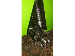
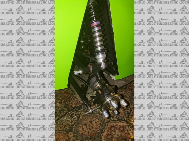
RearSuspensionPartBuilt
I didn't fancy rebuilding calipers myself, and I wanted a high-quality finish in keeping with the colour scheme, so I had Bigg Red rebuild the
calipers and apply their green polymer paint to them.
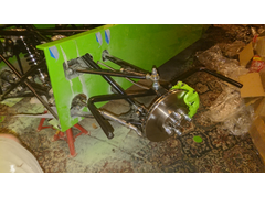
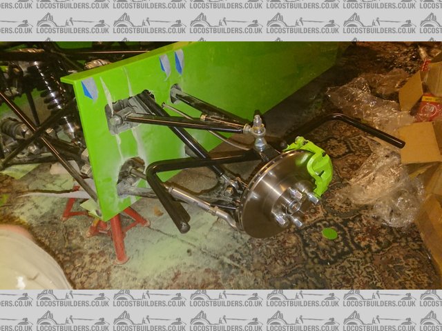
BiggRedFront
And the rear. To anyone reading this blog, please note that the brake hose routing shown here is wrong. I corrected it just before mounting the
wheels.
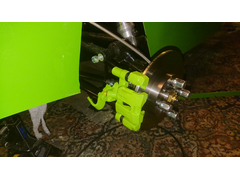
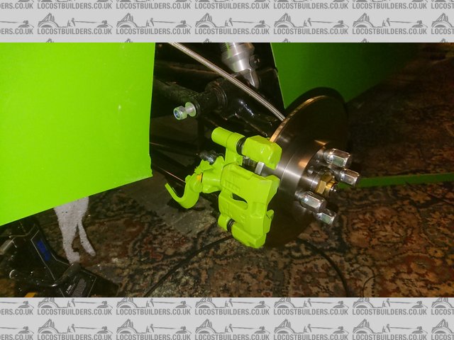
BiggRedRear
And then.... TOUCHDOWN! She stands on her own four wheels for the very first time, and in that instant transforms from a bag of bits to a car.
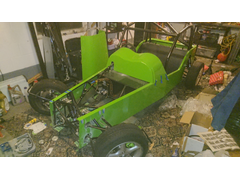
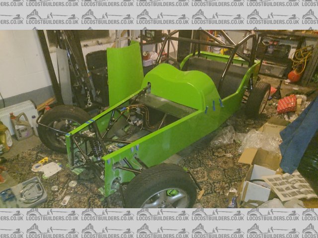
TOUCHDOWN
Having had pretty much every tool out, and with the garage floor covered in fibreglass, I had to have a thorough tidy up. The remaining parts are
either the bits of bodywork hanging up, or limited to just one pile of boxes under my workbench. This is also the first time in two years I have been
able to access my inspection pit.
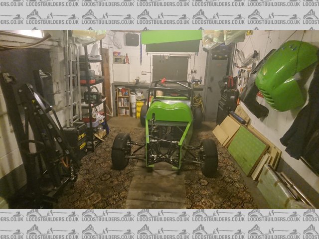
TouchdownTidyUp
Getting the car on its wheels is an important milestone. I need to temporarily evict her from the garage for a day so I can do a major service on the
daily driver.
[Edited on 13/12/2017 by micksalt]
micksalt - 14/8/18 at 01:22 PM
The project hasn't stalled, just on a bit of a slow-down, mainly due to the ridiculous temperatures in the garage. Got back onto it properly last
night with rear wheel arches and rear panel fitted, amazingly, with no mishaps
micksalt - 16/5/19 at 08:12 PM
Build blog continued at:
https://www.mnrsportscars.com/forum-1/vortx-mazda-builds/mick-s-mnr-vortx-mazda-build-continued


