
Mr Madinventions - help please, Ford ECU etc
monkeyarms - 30/6/11 at 06:53 PM
Or any other Ford ECU gurus?
Fitted into my Sylva J15 I have a 1.4 zetec, key, ecu & loom all from my doner fiesta.
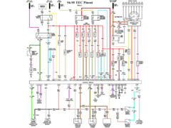
After reading this thread on the puma wiring and studying the
Ford TIS DVD i have arrived at the following -
Fuel pump drive - C1 pin 16
Ig pos II run - C1 pin 6
Ig pos III start- C2 pin 4
Pats wiring is uncut from my loom so should be ok.
Could i trouble you to check if you think the above are right to test fire the engine (i think it would be same as your 1.25 install?)
I am just double checking before connecting the battery, and your advice to others has really help me so far thanks 
Many thanks
Richard
mad4x4 - 1/7/11 at 06:54 AM
Not sure if these will help this is the pinouts of ECU IV & ECU V IIRC
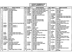
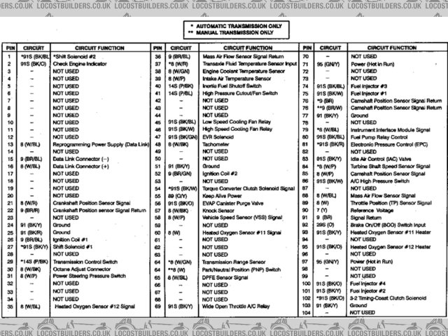
DuratecPinout 104
And

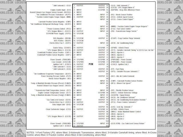
AUPCM6 Pinout (104)
and
ECU IV 60 Pin
Andy
[Edited on 1/707/11 by mad4x4]
monkeyarms - 1/7/11 at 05:00 PM
quote:
Originally posted by mad4x4
Not sure if these will help this is the pinouts of ECU IV & ECU V IIRC
Images
Andy
[Edited on 1/707/11 by mad4x4]
Andy, thanks for the diagrams, but i cant quiet read them, any chance of bigger copies please?
Richard
Madinventions - 3/7/11 at 12:27 AM
Hi Richard,
What year was your Fiesta? I'm now looking at the 96-99 Fiesta wiring diagrams on the TIS DVD to double check the connections. My 1.25 was a 96
base model and didn't have any extra like alarms, PAS, AC etc so the wiring loom was relatively simple.
Fuel pump:
C1/16 out to fuel pump via violet/orange wire. Check the inertia switch isn't activated (this caught me out once...)
Ignition key:
Start (pos III) grey wire to C2/4
Run (pos II) Vt/Og wire to C1/6. This feeds ECU pins 71 and 97 which are 'ignition +12v'
PATs transponder (just to check)
Pin 1 - Ye/Gn wire to C2/15. On the 1.25 this is connected to +12V, on yours it may be from pin 41 on the ECU?
Pin 2 - Bk/Gn wire to C2/14 (ground)
Pin 3 - Gy/Og wire to C2/12. This is connected to ECU pin 38.
Pin 4 - Wh/Gn wire to C2/13. This is connected to ECU pin 5.
One other thing to just check: Pre 05/98 gearboxes have a 'neutral' switch which connects ECU pin 64 (bn/wh wire) to ground. My 1.25 also
had a 'clutch down' switch in parallel with this. If you have problems, it's worth a quick check to make sure that pin 64 is connected
to ground. See drgs: 29-03-007, 29-03-010 and 29-03-011.
You should hear the fuel pump run for about a second or so when the ignition is turned to pos II. It may also be helpful to connect the LED as
described in the thread you linked just in case there's a PATs issue?
From what I've seen, I think your connections are spot-on so I'll keep my fingers crossed that you get your engine to fire up first time!
Good luck!
Ed.
Strontium Dog - 3/7/11 at 12:51 AM
quote:
Originally posted by monkeyarms
quote:
Originally posted by mad4x4
Not sure if these will help this is the pinouts of ECU IV & ECU V IIRC
Images
Andy
[Edited on 1/707/11 by mad4x4]
Andy, thanks for the diagrams, but i cant quiet read them, any chance of bigger copies please?
Richard
Put your curser over the pics and they expand automatically
monkeyarms - 3/7/11 at 09:28 AM
Strontium Dog - I meant even when i mouse over, they still look fuzzy to me! 
Ed, My fiesta was registered 10/03/1998 and i think i remember it having a clutch switch, but I still have all the wiring looms, labled up, so I will
check to see what switch I have. I might still have the clock too.
My fiesta had PAS and I have been informed (thanks RichN) that i need to look for a PAS related connector that affects tick over.
It was last year when I stripped the fiesta so Im glad i labled and kept all the looms.
Many thanks for everyones help so far, I will let you know how i get on, finger crossed!
Richard
monkeyarms - 3/7/11 at 07:37 PM
Well I tried to start my engine and it wouldnt turn over, so I will list what i have now..
On key Pos2 relays click into life, pos3 starter relay clicks but no turn over.
No fuel in tank (surely not needed to turn over?)
I have 12v to fuel pump on key pos 2, but no sound from pump, only relay sound from fuse box (would failed pump prevent turn over?)
I have 12v to C2 pin 5 when key at pos 3
I have located the clutch switch on my loom, it completes a circuit between C1 pins 4 and 5, tried both open and closed.
I am a little unsure as to the exact pin numbering convention on the ECU connector, but I can only find 1 bn/wt wire as shown in the picture, bottom
row 3rd from right, it tests as earthed ok.
Do I have a 60 pin ECU?


ecu connector
My PATS wiring is straight fom the loom from key antenna to C2 (also correct pins as per Eds post) although i did accidentally cut 1 wire and have
twisted it together temporarily (continuity tests ok).
Inertia switch ok (tried in both positions)
I have connected as many earths on the loom as i can see/find back to battery earth cable which also earths engine, lifted straight from doner fiesta.
checked all fuses = ok
tried both the keys i have.
Engine not siezed!
Battery seems ok, but I guess trying another/jumper cables from another car would be sensible?
[Edited on 3/7/11 by monkeyarms]
Strontium Dog - 3/7/11 at 10:22 PM
quote:
Originally posted by monkeyarms
Strontium Dog - I meant even when i mouse over, they still look fuzzy to me!
Richard
Oh bugger! 
[Edited on 3/7/11 by Strontium Dog]
Madinventions - 3/7/11 at 11:44 PM
Oh, that's a 60 pin ECU. All of mine were 104 pin versions. Anyway, the Ford drawings show the 60 pin variant so let's check a few
things.
Firstly, here's how the pin numbers run on your photo.

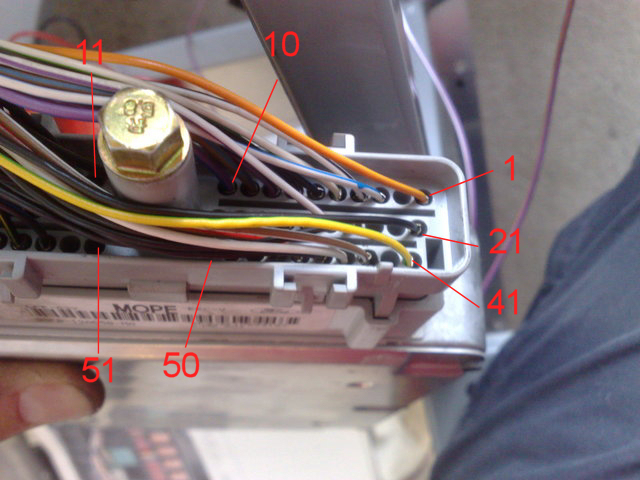
60 pin ECU pin numbers
I've gone through all of the Ford TIS drawings for a pre 05/98 ECU and drawn up a pinout:
1 Permanent +12v (og/ye)
2
3 Speed pulse signal (wh/rd) - I see yours is wh/bu though which is post 05/98 according to Ford...
4 Tacho pulse output to dashboard (wh/bk)
5 PATs transceiver (wh/gn)
6 A/C high pressure switch (bk/bu)
7 ECT coolant sensor (bk)
8 Fuel pump sense(?) Connected to output of fuel pump relay before inertia switch. (vt/bk)
9 MAF sensor (bn/bu)
10 To/from A/C system if fitted (vt/bu)
11 Cannister purge solenoid (bk/og)
12 Injector 1 (bk)
13 Cooling fan relay drive (bk/bu)
14 Injector 4 (bk)
15 Injector 2 (bk)
16 Ground (bk/ye)
17 'Data link connector' pin 13 (wh)
18 'Data link connector' pin 10 (bu/wh)
19 'Data link connector' pin 2 (gy/vt)
20 Ground (bk)
21 Idle speed control valve (bk)
22
23
24 Camshaft position sensor (bk)
25 Air temperature sensor (wh/vt)
26 Throttle position sensor reference(?) (bk)
27 +12V via F34 (if fitted). F34 fitted for high octane fuel. (wh/bk)
28 Power steering pressure switch (wh)
29
30 Camshaft position sensor (bk)
31 Extra high speed cooling fan relay drive for vehicles with A/C (bk/wh)
32 PATs immobiliser output connected to starter relay. Will be ground during cranking if PATs is ok. (bk/bu)
33 Lambda sensor signal (bk/ye)
34 Injector 3 (bk)
35
36 'Data link connector' pin 7. No wire colour listed.
37 Switched +12V power (vt/ye)
38 PATs transceiver (gy/og)
39 PATs transceiver (bk/og)
40 Ground (bk/ye)
41 PATs transceiver (ye/gn)
42
43 Neutral/clutch engaged switch (bn/wh)
44 Lambda sensor heater (wh)
45 Alternator (bk)
46 Sensor reference common (ground?) (common to many sensors) (bn/rd)
47 Throttle position sensor input (bk)
48
49
50 MAF sensor (wh/bu)
51
52
53 Fuel pump relay drive (bk/bu)
54 To/from A/C system if fitted (bk/ye)
55 Crankshaft position sensor (bk)
56 Crankshaft position sensor (bk)
57 Switched +12V power (vt/ye)
58 Coil pack drive for plugs 1 & 4 (bk/og)
59 Coil pack drive for plugs 2 & 3 (bk/gn)
60 Ground (bk/ye)
Drg 26-01-002 definitely shows ignition POS III going to C2 pin 4, not C2 pin 5. Is it definitely the starter relay clicking? If so, have you got
+12V onto the smaller wire on the starter motor when it should be cranking? F36 (60A) is the starter fuse. Could just be a duff starter relay?
Drg 29-03-014 shows the fuel pump wiring. Have you earthed the pump/sender assembly? F35 (10A) is the fuel pump fuse. The pump should spin up every
time the key is turned to POS II.
It's probably best for the pump to have a little fuel. Here's my coffee pot fuel tank I used for testing!

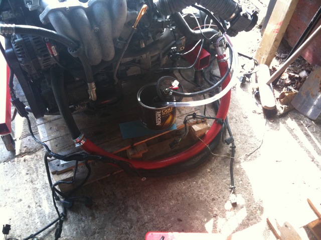
Coffee pot fuel tank
Does you ECU match up to the connection list above? It may be a Ford parts-bin-special because they changed over to slightly different wiring in
05/98.
Let me know how you get on. We'll get that engine running one way or another!
All the best,
Ed.
[Edited on 3/7/11 by Madinventions]
RichN - 4/7/11 at 11:19 AM
It will turn over without fuel.
I think that there are 2 possibilities:
1) The starter moter is seized. This happened on mine. Put the car in gear and rock it back and forward a couple of times, this cured it for me.
OR
2) The Immobiliser is not recognising the key. If you have the clock then connect it and earth it then look at the LED. If if goes out then all is
well, if it flashes rapidly then it's not picking up the key and won't start.
Let me know how you get on.
[Edited on 4/7/11 by RichN]
monkeyarms - 4/7/11 at 04:31 PM
Thanks guys, I will check the things you have pointed out.
Ed the Ign Pos 3 pin5 was a typo, tired and rushing on computer etc, it was connected to pin 4
Rich I will look for the started thing, but on the clock, I do have it, BUT, that half of my loom is in a sorry mess at the moment. Would you (or Ed)
know how to splice the clock to the ecu/fuse box?
It will be a couple of days before I get in the garage again, but many thanks for you time and help so far guys.
Watch this thread for progress!
Richard
RichN - 5/7/11 at 07:02 AM
Richard,
My Fiesta was a 1996 model, so you ought to double check this yourself on the TIS.
The clock had:
Og/BK which linked into OG/Ye (pin 6) - this is a permanent live
Vt/Wh into Vt/Ye (1) - Switched live from ignition position 1 (this illuminates the clock)
Bk (3) - Earth
Bk/Bu into Bk/Og (4) which is the LED.
The pins are from the Haynes manual so I would check them first as I found errors in their diagrams. If you can find the plug in your loom then this
would help for the connections.
I would imagine that you only need the LED and Earth to be connected.
Good luck.
Richard
[Edited on 5/7/11 by RichN]
monkeyarms - 5/7/11 at 07:59 PM
Long story short, no +12v to starter motor (small wire)
connect clock - confirmed pats is happy
fuel pump ok now i pushed in tank connector on properly (oops!)
pin 43 on ecu test ok to ground - even ran a wire direct
fuse 36 ok
put car in gear and rocked lots to free starter motor if stuck
jumper leads from my focus to check duff battery
removed starter relay to check-
+12v to pin 3 on relay base ok
continuity from relay base pin 5 to starter motor ok
When i turn the ket to pos3 start, with my finger on top of the relay i can feel it click, but no power is going to the starter motor.
So i guess it is a faulty starter relay, but would it still click if faulty? I suppose i need a spare to check it, or can i test it ?
I feel im close now!
Cheers guy so far.
monkeyarms - 6/7/11 at 12:26 PM
 it isnt the relay, i tried 2 spare ones from the internal fuse box. unless all 3 are faulty.
I am at a bit of a loss now.
I guess going over all my connection and double checking everything is wise.
Any ideas guys ?
No 12v to starter motor is where im at.
garybee - 6/7/11 at 01:01 PM
Surely if your starter relay is "clicking" but no feed is getting to the starter then it's either the feed to the relay (high capacity
side) or the feed from the relay to the starter.
RichN - 7/7/11 at 06:57 PM
From my Haynes manual the Starter Relay has:
a Rd permanent live via F36 which is one of the yellow 60amp fuses.
Gy which is from the ignition switch
Bk/Ye which can be connected to Bk/Bu, this is to Earth
Gy/Bk to Bk/Ro to the starter motor.
As the relay is clicking then I would guess that you have not got Rd via F36 or Gy/Bk to the starter motor.
I hope this helps and you get started soon.
Richard
monkeyarms - 7/7/11 at 08:03 PM
Well I have now got the engine to turn over, turned out to be the wire frim ECU to relay, I had accidentally cut when I decided to "trim a few
thing I dont need" off the engine loom. I am regretting that now!
Anyway, engine cranks over, fuel is at engine but not fired up.
I am going to study the TIS for wiring to coil pack to see if thats all ok. Anything else i could check guys?
Does the fuel system need "bleeding" or have i just made that up?
big_wasa - 7/7/11 at 08:35 PM
quote:
Originally posted by monkeyarms
Does the fuel system need "bleeding" or have i just made that up?
Just turning the ignition on and of will give you presure in the rail.
RichN - 8/7/11 at 09:12 AM
When you turn the ignition on to Pos II do you hear the fuel pump run for a few seconds? This gives it the initial pressure. I am guessing it does if
you have fuel at the rail.
You should not have to bleed the system at all.
So the next thing as you say is that there is no spark so it's the wires to the coil pack from the ECU.
There is a Power Hold relay that feeds Bk (Vt/Bu) wire via a Diode to the coil pack.
The coilpack is fired by Bk (Bk/Gn) for 2 of the cylinders and Bk (Bk/Og) for the other 2.
I would check for a spark in the plugs.
monkeyarms - 8/7/11 at 11:02 AM
Yes ther fuel pump definatly works, with fuel at the rail.
So i will check the coil pack next, I feel I am really close now
Fingers crossed it might be running this weekend!
Thanks everyone so far
monkeyarms - 9/7/11 at 02:53 PM
I still havent got the engine to start. There is no spark at the plugs. So -
I have put a new coil pack on just in case.
There is 12v to the coil pack connector
The 2 wires from ECU to coil pack check ok for continuity
The ECU pin 43 clutch switch is directly earthed like Ed suggested
Cranks over on key pos3 fine
fuel to rail - ok
fuel pump - ok
PATS - ok
So it seems the ECU isnt telling the coils to fire. I am stuck now, i really don't know what to check next, or what to do
Thinking the worst, could the ECU be duff? Could i have damaged it with some ham fisted testing? It was working ok when stripped from doner, then
bubble wrapped and left alone in the shed for a year, untill now.
[Edited on 9/7/11 by monkeyarms]
Madinventions - 10/7/11 at 04:58 PM
Those Ford ECU's are pretty resilient so I would think that it should be ok...
Have you checked your camshaft and crankshaft sensors?
It may also be worth getting one of the cheap OBD error code interfaces from eBay (search for ELM327) and see if there are any error codes in the ECU.
You'll get the standard 'cannister purge solenoid' fault probably but this doesn't stop mine working, and the error code may
shine some light on the issue?
Ed.
RichN - 10/7/11 at 05:36 PM
On Ed's advice I bought an OBD reader off Ebay (really for piece of mind), I get the canister purge registered but, as Ed says, it runs fine
without it, I've done 1300 miles now.
You say that you have 12 volts to the coilpack but are you firing the plugs. In my earlier post there are 2 other wires to the coil pack that are
connected to the ECU.
Also have you earthed the engine block to the chassis?
Keep trying, you're nearly there.
monkeyarms - 10/7/11 at 06:27 PM
Ed, I havent checked the cam&crank sensors, what's the best way to check their function? I will check that the wires are ok. I will consider
a OBD tester too thanks.
Rich I have checked the 2 wires you mention, they test ok. My earth is the fiesta battery cable to engine, I don't have a specific chassis to
engine earth cable but the chassis is earthed via the mounts/bolts if that makes sense?
Can i just confirm chaps the fuel supply is the top connection on engine, with the return below it? I did mark these sort of things when I dismantled
the doner, but im doubting everything now!
many thanks chaps.
RichN - 11/7/11 at 06:52 PM
Your fuel lines are correct. The top one is the supply (white Ford connectors) and the lower one the return (red Ford connectors).
I guess you will have to check all of your ECU wiring as per the diagrams and Ed's earlier post.
Have you got all of the ECU earths connected?
Keep us posted.
monkeyarms - 11/7/11 at 08:06 PM
Right, I may have got to the bottom of it. It could be a faulty camshaft sensor. After some reading up I figure out how to test the sensors, and the
crankshaft sensor seems ok, but nothing from the camshaft sensor.
So I will fit a new one and cross my fingers!
garybee - 11/7/11 at 08:52 PM
I believe the cam sensor is an inductance sensor, how did you go about testing it?
I don't think a failed cam sensor would stop the engine starting anyway.
monkeyarms - 12/7/11 at 07:04 AM
Gary read this article linky, here is the relevant
part...
One of the two wires is the Signal wire that sends the Signal to the Fuel Injection Computer of Ignition Module.
The other wire acts as a Ground return. This Ground is always provided by the Fuel Injection Computer or the Ignition Control Module.
On this type of Sensor, you'll connect both Multimeter Leads to both wires. That is the Red Lead can be connected to either of the two. The
Black Lead is connected to the remaining one. It doesn't matter which Lead goes where, since the polarity does not matter.
Your Multimeter has to be in Volts AC mode to see this Signal.
When your helper cranks the engine, the Multimeter will display about 1 Volt AC. Usually, this AC Voltage will move between .3 Volts AC to 1 Volt
AC the whole time the engine is cranking, this is normal. If the Sensor is BAD, the Multimeter will not display any AC Voltage.
This Voltage increases with Engine RPM's. So the faster the engine cranks, the higher the AC Voltage.
I really hope it is this sensor and it solves my problem!
monkeyarms - 12/7/11 at 05:25 PM
Predictably the new cam sensor did nothing.
I am now thinking what i can check next. Would a duff alternator prevent start up? The alternator seems to be connected to ECU pin45, should this be
earthed when cranking?
I think a OBD reader may be needed, which is best, a hand held or laptop style one?
I am getting fed up with this now
rich
[Edited on 12/7/11 by monkeyarms]
RichN - 16/7/11 at 05:00 PM
How are you getting on? Have you made any progress?
If you're still struggling then post some pictures of your fuse box (open so all of the relays and fuses show - I assume you've removed the
ones that you don't need) and ECU wiring. If possible an overall view of your installation may help.
I will then compare with mine, especially the fuse box.
Don't give up.
monkeyarms - 17/7/11 at 04:05 PM
Hi Rich, It was my 40th birthday friday and had a party saturday night and feeling a bit fuzzy in the head today! So I have not been on the car for a
while.
I have bought a OBD reader off Ebay and will try it in the next day or 2.
Thats a good suggestion about pics of fuse box. When Im in the garage next I will get snapping.
Thanks
Richard
monkeyarms - 18/7/11 at 07:25 PM
I have tried the OBD reader and it gave no error codes. The software said it had connected ok but only after a bit of messing with connection settings
(something about connecting with aux input?). I didnt seem to be able to retrieve any other information from the ECU but I dont know what to expect if
it is ok.
So here are the pics of open fuse box... (all fuses are ok)
In this picture you will see i used the green connector off the loom, my idea being to keep the black connector on the loom to trace wires etc.


In this picture you can see where i made the stupid desicion to "trim off what i dont need" turns out the wire for the starter relay and
clutch switch are in there. Also is a Bk/Blue wire that goes to ECU pin 46, this is grounded.
Can anyone see something wrong?
RichN - 19/7/11 at 06:57 AM
I will have a look at my fusebox later and get back to you.
When you connected the OBD reader did you have the ignition on (Pos II)? My reader would connect OK but wouldn't read anything until the ignition
was on.
I would expect you to get a cannister purge error assuming you have removed this from the engine.
monkeyarms - 19/7/11 at 10:12 AM
Yes I did have key at pos 2 when reading.
I am wondering if the ECU has a fault.
Thanks Rich
monkeyarms - 19/7/11 at 06:02 PM
After more time in the garage working on the wiring/ecu, I am more and more thinking that I may have a faulty ECU.
I have checked my wiring and cant find anything wrong and that the OBD reader doesnt get any fault codes or other data seems to point to ECU
problems.
So what are my options here to test ECU?
Would a similar 60 pin ford ECU (plus key) at least try to start the engine, ie borrow one to test or scrap yard find similar, or do I need the exact
same ECU?
Or send mine off to be be tested and/or repaired as needed?
RichN - 19/7/11 at 06:41 PM


Aux Fusebox Plug Map
These are the wires that I have connected to the 3 plugs. I can't remember what they all do, but if they fed to the ECU (apart from the Reverse
Light Switch) then I left them in.
Your fuses and relays look correct.
If you're not getting anything out of your OBD reader, then have you got the data port wired up correctly? I believe there are 4 wires (Bu/Wh),
Gy/Vt, Bk (earth and to the ECU) and Bn/Rd.
Also are you getting power to the ECU? Check the wiring out of fuse F28 in your box, this feeds power through 2 wires (both Vt/Og) to the ECU from the
ignition barrel (Gn) though F18 in the Central Fusebox through the Diode and into the Power Hold Relay.
I would imagine that all of this is correct.
Did you see/have the donor car running before it was stripped down? If so then it's unlikely that your ECU has broken in that time.
I don't know what else to suggest.
Keep us posted.
hearbear - 19/7/11 at 07:58 PM
Have you tried the reader on another car just to check there is no problem with it.
George
monkeyarms - 19/7/11 at 08:16 PM
Rich your plug map is great but i cant make out the text. I think its when this web site resizes the pictures to 640x480 definition gets lost.
Any chance of clearing the picture up please?
The data port is untouched from the donor loom so should be ok. I drove the donor fiesta 30 miles home and it was fine, quite nippy!
I will double check the power to ECU as you suggest.
Also I will check the OBD on another car when I get chance, brothers step daughter has a S reg 1.25 fiesta!
Many thanks for you help so far everyone.
Rich
RichN - 20/7/11 at 09:21 AM
I am looking at these from the back of the fuse box (the bit that’s against you’re bulkhead).
I can’t modify the pic as I am in work, but I’ll try and describe.
The Green Plug
Top row left to right
Vi/Wh
Bottom row left to right
Og, Wh/Bk (tacho)
White Plug
Top row left to right
Gy/Og, Wh/Gr, Bk/GR, Ye/Lt Gr, Bk/Og
Bottom row left to right
Bk/Gr, Gy (from the ignition barrel (Pos III), Vi/Og (from the reverse light switch (non-ECU))
Black Plug
Top row left to right
Vi/Og
Bottom row left to right
Bl/Bk, Br (clutch position), Br (clutch position), Vi/Og, Wh/Bk
Let me know if this doesn't make sense.
As you have driven the Fiesta I would doubt that the ECU has developed a fault whilst it has been in you garage.
[Edited on 20/7/11 by RichN]
monkeyarms - 20/7/11 at 11:44 AM
Rich, you have U2U
Thanks for the info, that clears it up
monkeyarms - 25/7/11 at 05:50 PM
Still no start up, cranks ok.
RichN is possible coming to help me this weekend so I am trying to clear up a few things in my head beforehand, so may I trouble you to look at the
following?
Will start up happen if –
No dash light for alternator is connected
Alternator is faulty i.e. start on battery power only, as ECU is connected to alternator (is possible to test the alternators working?)
Any other dash lights not connected
Other than ign pos 2 and 3, PATS, fuel pump and clutch switch what other essential connection should I be making?
For info, all wiring to sensors checks ok and I have fitted a new coil pack, cam & crank sensor.
At the back of my mind I am still thinking my ECU could be faulty, to test this would a similar one + key work or is a like for like needed?
How on earth did you start your engine on a pallet and I can’t start mine in the car!
Madinventions - 29/7/11 at 12:53 PM
Did you ever manage to get anything from the OBD reader? Did it work on the other vehicle? Does your software support viewing 'live
data'?
The ECU connection to the alternator is so that the ECU can control the output voltage. Most alternators used to have internal regulators but modern
versions use the ECU to do the regulation so it's probably important to have this connected.
I'll go through all my notes again tonight to see if I did something that I've since forgotten about. The only real difference is that I
used a loom that didn't have any cut wires so my money is still on there being one wire somewhere that we need to find and connect.
Ed.
Madinventions - 29/7/11 at 10:48 PM
Ok, I'm going through the TIS DVD and just jotting the following things down as I see them, so there's no particular order to these
notes!
Double, and triple check that your throttle position switch is connected correctly. If the ECU thinks you have your foot flat on the floor during
cranking then it will go into 'flood clearing' mode where it will turn over without spark to help clear a flooded engine.
Check your 'ign pos 2' wire comes from the green wire on the back of the ignition switch (pin 6) and not the yellow wire (pin 1). The GN is
+12V during cranking, but the yellow isn't.
I've just found the wiring loom from the 1.7 engine that I used for the 'pallet start' video. It's very different, but I can try
and check some things if it'll help? I also found a rubbish video I took about the connections for the pallet startup, and all I had was
switched 12v, start 12v, PATs, and the fuel pump. All of the engine sensors were connected except the MAF sensor because 'I couldn't be
bothered' according to the video! There was no alternator warning lamp either...
I think that there are different versions of the ECU so I wouldn't be sure that they could be freely interchanged. Big_Wasa seems to have a fair
bit of knowledge on this so it may be worth dropping him a U2U.
I'll keep looking...
monkeyarms - 30/7/11 at 05:24 PM
With a big thank you to forum member RichN for coming eround to help me, he spoted the problem.
I had 2 wires wrong way round into ignition. Swapped round it started, ran then died. 2 blobs of blue tack in the surplus vacuum tubes in the throttle
body and it ran superb also diagnosed a missing wire to the OBD port so we tested that and it came back with just the expected emissions canister.
So very happy now.
Ed, looks like you last post was pointing me in the right direction with checking ignition wiring.
Heres a video after I cleaned up a little
[Edited on 30/7/11 by monkeyarms]
Madinventions - 31/7/11 at 06:18 PM
That is absolutely fantastic news, and well done to you both for getting it sorted! Isn't it a great feeling when you finally get the engine
running?
I'll look forward to meeting up at Stoneleigh one year, and keep us posted re progress!
Ed.


