mark chandler
|
| posted on 13/4/14 at 06:52 PM |

|
|
Hydraulic help
I have a small mini digger, a powerfab 180c and the 9cc hydraulic motor is on its last legs  engine is a 11hp Honda gx340 engine is a 11hp Honda gx340
I have got a new 10cc motor, fitted it and power is fully restored, if anything it's too much now as when holding on the controls the engine
stalls, even though the engine is undersized by 1hp I would expect it to be dragged down but not stop. When walking on its tracks it's fine,
perfectly usable as long as the rams are moving.
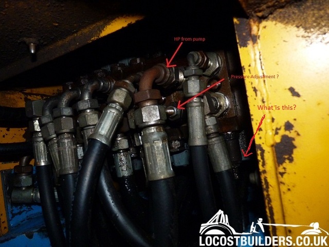
So looking at the lever block the pump plugs into the bar, directly below where it terminates the pump feed there looks at what may be an adjustment,
would you have something to set here? I cannot see anywhere else that may allow me to regulate the pressure, any suggestions
There is also a bypass block, this looks to be sealed for life, I assume it's just an over pressure protection device, it has a small bypass
hose to the return pipe.
Unfortunately no manuals for this
Thanks Mark
|
|
|
|
|
coozer
|
| posted on 13/4/14 at 07:00 PM |
|
|
Interesting, got any pics of it?
1972 V8 Jago
1980 Z750
|
|
|
mark chandler
|
| posted on 13/4/14 at 07:18 PM |
|
|
http://www.oilyhands.co.uk/Powerfab_diggers_excavators.htm
It's a 180c, picture 1/3 of the way down, the yellow one.
http://www.oilyhands.co.uk/Powerfab_180C-digger.htm
More manuals for the lesser machines show a similar valve block and mention pressure relief shims, mine seems to have two extra blocks if that makes
sense that only terminate the high pressure pipe into the valve block and what may be an adjustment nut + a single block for the return to the
tank.
It could have been fitted with a 9hp engine so I think something is amiss on the pressure relief side.
[Edited on 13/4/14 by mark chandler]
|
|
|
daviep
|
| posted on 13/4/14 at 07:37 PM |
|
|
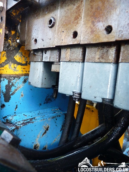
Any pics of the valve block?
A truly great library contains something in it to offend everyone.
|
|
|
mark chandler
|
| posted on 13/4/14 at 07:50 PM |
|
|
Here you go

Its masked by the hose but looks like an allen headed screw and lock nut.
[Edited on 13/4/14 by mark chandler]
|
|
|
daviep
|
| posted on 13/4/14 at 08:29 PM |
|
|
Could be, but not where I would expect to see it. I've added another arrow to your pic in the rough area I would have expected it to be. I take
it you want to drop the pressure, if so no harm in backing the screw out as long as you count the turns and/or leave the lock nut where it is. Do you
have a gauge so you can see what's happening?
A truly great library contains something in it to offend everyone.
|
|
|
carlknight1982
|
| posted on 13/4/14 at 08:37 PM |
|
|
another thing to try is drop the engine revs so the pump isnt running as fast
Logic will get you from a A to B
Imagination will take you everywhere.
|
|
|
mark chandler
|
| posted on 13/4/14 at 09:05 PM |
|
|
Davie, that's the control for the dozer blade, the return to the tank is on the far left hand side, is this where you would expect adjustment?
I have an air conditioning gauge but nothing that would allow me to tee. Into any circuit. My measure of power is the ability of the dozer blade to
fully extend. With the new pump it easily lifts the front of the machine, with the old it takes the weight and lifts by maybe an inch when the fluid
is cold, as it heats it loses power to do this. I'm happy then that the motor is strong enough to run this pump but need to limit the pressure
and allow it to bypass before it stalls the motor.
Carlknight, running the engine at half speed or slower and it stops immediately you pull on any lever, it just not have the power unless cranked up,
it's as if there is no pressure relief so the pump just brakes the engine to halt in seconds. I have checked the engine regulator and that holds
the throttle wide open when under heavy load.
[Edited on 13/4/14 by mark chandler]
|
|
|
Dingz
|
| posted on 13/4/14 at 09:07 PM |
|
|
Can't really help I'm afraid, I suggest trying what Daviep suggested. The picture caught my attention as the fittings are Gates
Hydraulics, I used to help design them many years ago!
Phoned the local ramblers club today, but the bloke who answered just
went on and on.
|
|
|
tegwin
|
| posted on 14/4/14 at 08:16 AM |
|
|
Not an expert by any means.... But did the old pump have a pressure bypass on it? If the new one doesn't or it's set too high you will
stall the engine...
------------------------------------------------------------------------------------------------------------------------
Would the last person who leaves the country please switch off the lights and close the door!
www.verticalhorizonsmedia.tv
|
|
|
mark chandler
|
| posted on 14/4/14 at 02:17 PM |
|
|
No bypass inbuilt within the pumps, they look identical although externally there is a bypass which I suspect is for overload protection.
|
|
|
dinosaurjuice
|
| posted on 14/4/14 at 03:25 PM |
|
|
As the new pump is a larger displacement the only thing you can do is reduce the max working pressure, unfortunately this will also reduce the force
on all the functions, but without buying a larger engine not much else can be done.
The valve block should have a primary relief valve close to the inlet hose connection from the pump, will probably look like a threaded stud with a
locking nut, wind it out to reduce cracking pressure. Without installing gauges this will be a trial and error process.
If there doesn't seem to be such a thing on the valve block then it will be the pump bypass that needs adjusting (reducing), trial and error
once again.
|
|
|
mark chandler
|
| posted on 14/4/14 at 04:46 PM |
|
|
I also have a relief valve on the system, Tee'd between the pump outlet and the oil tank


This does not look like its adjustable ?
Made by Sun Hydraulics.
I,m happy to drop the max working pressure, at present I,m not sure if this function is even working ! I am sure the old pump is not capable of
generating the pressure anyway.
|
|
|
omega 24 v6
|
| posted on 14/4/14 at 04:51 PM |
|
|
Not that I know much about hydraulics BUT could you not put a tee in the supply line with a pressure relief valve back to the tank. Then set it at
whatever pressure you require??
Like I saidI don't know a lot but thought this would be possible.
If it looks wrong it probably is wrong.
|
|
|
mark chandler
|
| posted on 14/4/14 at 05:07 PM |
|
|
I think I have cracked it  however need to put the new pump back to prove. however need to put the new pump back to prove.
On the ECV above the threaded bit that sticks out and looks like it should have something wound onto it has been wound tightly in, it's an
adjustment so I can back this out and drop the max pressure.
I guess as the old pump started to fail they just locked it up tight which would have seen off the dying pump and explains why it kills the engine
dead with the new pump.
Thanks for the help chaps, I will report back in a few days.
[Edited on 14/4/14 by mark chandler]
|
|
|
dinosaurjuice
|
| posted on 15/4/14 at 03:34 PM |
|
|
quote:
Originally posted by mark chandler
I also have a relief valve on the system, Tee'd between the pump outlet and the oil tank
This does not look like its adjustable ?
Made by Sun Hydraulics.
I,m happy to drop the max working pressure, at present I,m not sure if this function is even working ! I am sure the old pump is not capable of
generating the pressure anyway.
that's a counterbalance valve which is being 'badly' used to prevent return line flow when the system pressure falls. Might be a mod
to prevent the anything moving when switched off, possibly due to a worn spool valve or similar.
|
|
|
mark chandler
|
| posted on 15/4/14 at 06:08 PM |
|
|
Does this mean winding back the valve in the ECV will make no difference to the maximum working pressure ?
I have now looked more closely where Davie expected an adjustment and found this
Hopefully this is what I need to back out?
[Edited on 15/4/14 by mark chandler]
|
|
|
daviep
|
| posted on 15/4/14 at 07:14 PM |
|
|
quote:
Originally posted by dinosaurjuice
[that's a counterbalance valve which is being 'badly' used to prevent return line flow when the system pressure falls. Might be a
mod to prevent the anything moving when switched off, possibly due to a worn spool valve or similar.
Indeed it is, well spotted!
Hard to tell from the photo but that looks like a very poor set up of the suction hose, an arrangement where the pump must pull the oil up a stand
pipe is asking for problems, any air leaks will cause cavitation and damage the pump relatively quickly. Also having the suction of the pump on the
upper face is not good practice as the pump won't prime as easily as if the suction was on the lower side of the pump, so make sure the pump is
fully primed before giving it any load and make sure that the connections on the suction side are nice and tight, if the oil becomes foamy then you
have an air leak on the suction.
Normal practice is a gravity feed in to the bottom of the pump.
Cheers
Davie
A truly great library contains something in it to offend everyone.
|
|
|
mark chandler
|
| posted on 15/4/14 at 07:30 PM |
|
|
Feed out the top is how it's designed, it does look awful but the hose fits well with no air bubbles but I'll keep an eye on it, thanks
for the tip.
When I got it the oil was very grubby and the filter was missing, also a number of little bolts are wrong as witnessed in the photo. Once I've
done my immediate digging I'll strip and refurbish it as a late summer project
|
|
|
mark chandler
|
| posted on 17/5/14 at 04:29 PM |
|
|
Digger all up and running now, had to get a more powerful motor, 16hp and it's working well, or rather was
One of the distribution valves is leaking badly, I have pulled off the cover and the plungers are sealed with two O rings, then a metal hoop presses
down on top held in by the base plate.
These look just like ordinary O rings so I swapped out with some new ones, this fixed it for a short while but they have now broken down, I was
expecting to see seals like you get in a brake cylinder with square shoulders, can anyone confirm what I should have?
The plungers measure 0.625" or 15.88mm and look to be in good condition.
Thanks Mark
|
|
|