
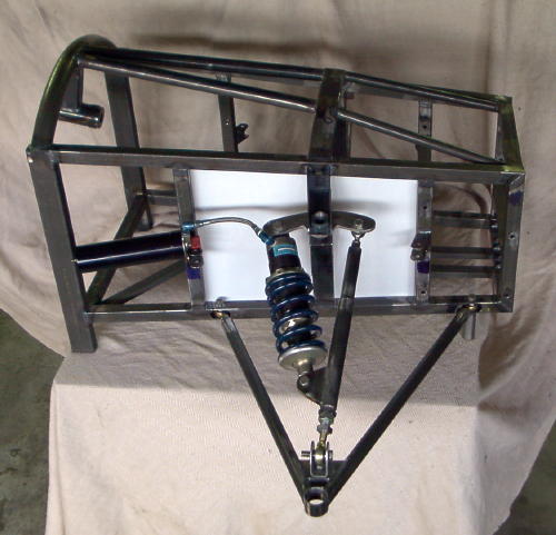
I found this browsing through Kurt Belinskis Midlana site. Its not from Midlana though

[Edited on 2/3/16 by liam.mccaffrey]
I'm an engineer and this picture troubles me, I flip flop between understanding how it works and being baffled
I found this browsing through Kurt Belinskis Midlana site. Its not from Midlana though
[Edited on 2/3/16 by liam.mccaffrey]
It's a method of increasing the stroke of the spring/damper, while staying compact.
Wot Designer said.
This picture of the arrangement from a different angle might help:
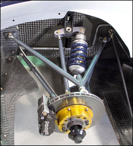
This might make it a little clearer. It's an interesting set-up and seems to work just fine in D-sports.
Edit: Sam beat me to it.
[Edited on 2/3/16 by cs3tcr]
I like it! Very slick, ive never seen this arrangement before.
[Edited on 2/3/16 by liam.mccaffrey]
Here's how I see it.
As the wishbone moves up in its arc, it pushes up on the bottom of the shock.
The pushrod also pushes up, but against the pivot.
The pivot pushes down on the top of the shock.
Twice as much travel on the shock.
Wouldn't the inner joints on the upper wishbone and the shock be much better turned through 90 degrees.
I think continuous movement under load in that plane would see them off really quick
Nope, im happy with that.
The suspension goes up, the rod that is attached to the shock at one end and the rocker at the other pushes against the rocker. That rotates the
rocker, compressing the spring.
Its just like a normal bell crank but the photo angle dont help.
JeffW F2 indycar front ARB is a good one for this. I think its anti dive and an ARB controller so its 2 functions in one.
Rocker reverses travel, therefore you end up with two points moving towards each other. Not seen that before, pretty neat!
The old Ducati 916 used this technique on the rear suspension.
Niklink as used on radicals since the late 90s.

At first glance it looked as if someone made a mistake & there would be no pivoting action at all. At second glance I see the movement, but it seems like that's a lot of force on that one rod. Would that be a problem?
Most monoshock sports motorcycles use the same principle.
It also allows an adjustable none linear motion ratio which is why it's used rather than the 'normal' shock/spring between arm and
chassis.
Ian
quote:
Originally posted by SCAR
Wouldn't the inner joints on the upper wishbone and the shock be much better turned through 90 degrees.
I think continuous movement under load in that plane would see them off really quick
I would think there could be considerable forces on the upper wishbone during cornering. As the tyre grips the road the lower wishbone mount would act
as a pivot point for the hub carrier subjecting the upper wishbone to either compression (inside wheel) or tension (outside wheel) loads. No idea of
the magnitude though.
[Edited on 3/3/16 by SCAR]
quote:
Originally posted by SCAR
I would think there could be considerable forces on the upper wishbone during cornering. As the tyre grips the road the lower wishbone mount would act as a pivot point for the hub carrier subjecting the upper wishbone to either compression (inside wheel) or tension (outside wheel) loads. No idea of the magnitude though.
An example of this suspension is detailed either on Milliken/Millike Race Car Dynamics or Competition Car Suspension by... ??? can´t recall now.
It is used to increase damper range of movement with very small wheel travel set-ups.
Those are cool, From my work

c17 undercarriage
The left hand wheel ends up at the front of the wheel pod and at 90 deg to the centreline of the aircraft. It's also a double wishbone
suspension, but to allow the verticalpost to come into the pod the side of the aircraft moves out of the way. 1 1.5" dia actuator moves
everything including the doors.
Engineer being a loose term then?
Go on then I'll bite I can't help myself, I suppose you're fully qualified to critique what an "engineer" should find
interesting? Are you chartered then or a fellow maybe?
quote:
Originally posted by sam919
Engineer being a loose term then?