jim87
|
| posted on 26/5/16 at 12:46 PM |

|
|
quote:
Originally posted by micksalt
Bummer, the MNR push-rod fix doesn't work. It seemed like an elegant solution in principle, but the washer and push rod hold the master cylinder
too far in for the inlet ports to be exposed, so there's no way to get fluid into the system. A little bit disappointed if I'm honest, I
expected something more like my proposal after waiting months 
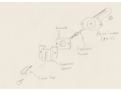 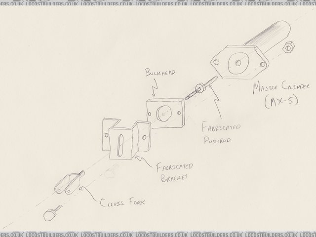
MX5Pushrod
Maybe you could shave a few mm off the piston to make space for the washer ? Seem to remember there's plenty of meat on the piston, but I dunno
whether it's a good idea on important brake parts ?
|
|
|
|
|
micksalt
|
| posted on 26/5/16 at 02:22 PM |
|
|
*** EDIT: the push rod fix DOES work, please see my follow-up thread ***
I'm thinking that I might just go for the Westfield
Option.
[Edited on 28/5/2016 by micksalt]
|
|
|
micksalt
|
| posted on 28/5/16 at 10:30 AM |
|
|
Well, this is embarrassing, the push rod fix DOES work  . I was trying to pull fluid through using a vacuum pump and pipe directly against the
cylinder outlets, but then I thought I'd better test what happens with the push-rod fix NOT installed and I got the same result. I dug around in
my box of tricks and found a better rubber connector to connect to the outlets and sure enough, fresh fluid at all the outlets. Put the push rod fix
back on, and again, fresh fluid. I angled the push rod to quite a severe angle since this pushes the cylinder in slightly, and I still get fresh
fluid. . I was trying to pull fluid through using a vacuum pump and pipe directly against the
cylinder outlets, but then I thought I'd better test what happens with the push-rod fix NOT installed and I got the same result. I dug around in
my box of tricks and found a better rubber connector to connect to the outlets and sure enough, fresh fluid at all the outlets. Put the push rod fix
back on, and again, fresh fluid. I angled the push rod to quite a severe angle since this pushes the cylinder in slightly, and I still get fresh
fluid.
Apologies to anyone I mislead with my flawed testing
|
|
|
micksalt
|
| posted on 9/7/16 at 11:45 AM |
|
|
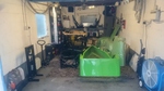
Finally finished with the restoration of the oily bits.
First of all, started with a proper scrub of the gearbox.
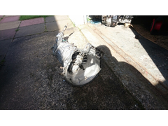 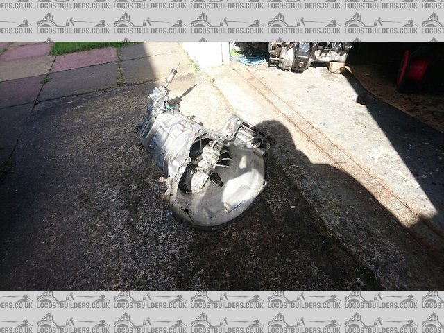
CleanGear
Fitted a new clutch release bearing, clutch release arm, gaiter, slave cylinder, turret seal and turret oil. Made the mistake of filling the gearbox
with oil, not realising that the seal relies on the driveshaft being inserted. Ended up with a very messy floor when I tilted the gearbox to put it
back on the engine.
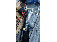 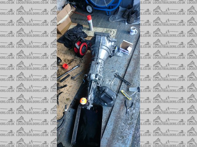
SlaveCylinder
After that mishap, engine and gearbox came together for the first time in a long while.
SlaveCylinder
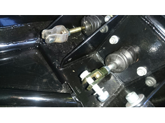
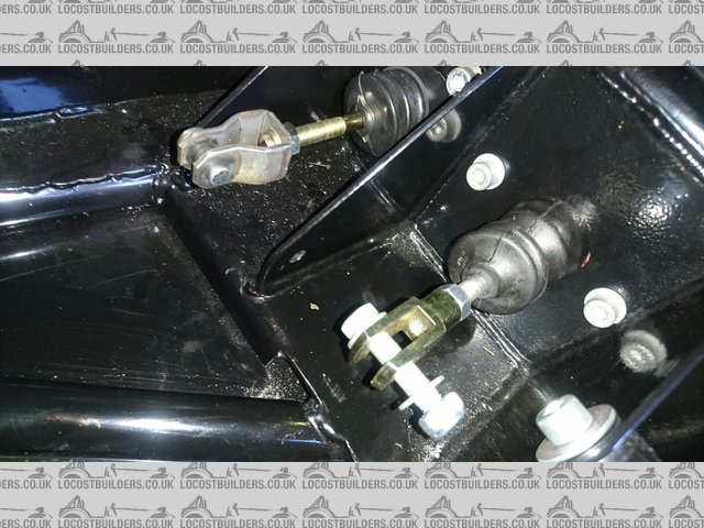
I've moved onto the actual kit itself now. Installed both master cylinders including the clevis pin assembly. Curiously, the brake master
cylinder is centred on the pedal, rather than centred on one of its vertical sections. This means that the clevis pin ends up between the two vertical
plates of the pedal, and you need a longer clevis pin to accommodate it. I'll post details when I install the pedals.
MasterCylinders
ClevisPins
Also trial-fitted the T-pieces required for the braking system. MNR fit a small tab to the chassis to hold this, which is a very nice touch.
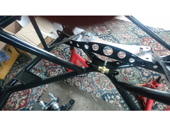 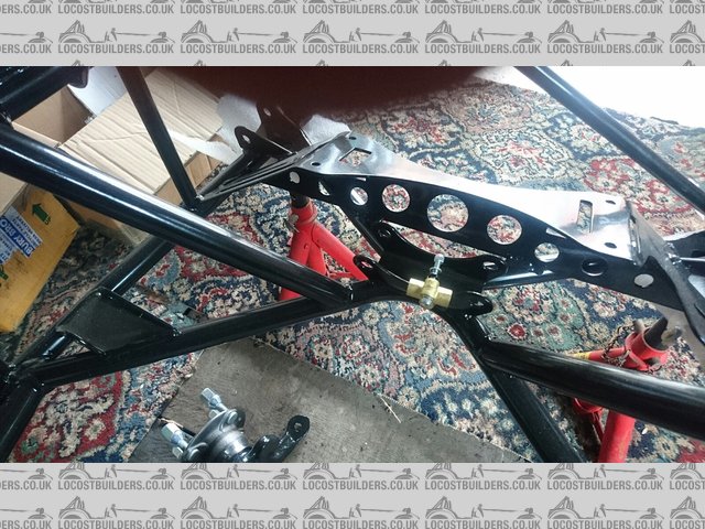
TPiece
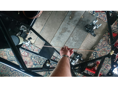
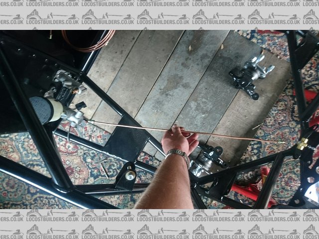
The brake hoses themselves have got me rather confused. To the left of my tape measure are the pipes that connect to the flexi-hoses, evidenced by the
fact they have the female connections on one end. What puzzles me about these though is that one is a very different length to the other. The T-piece
sits roughly in the middle of the chassis, and the chassis is symmetrical between the T-piece and the flexi-hose attachment points, so there seems to
be no reason that just one is much longer.
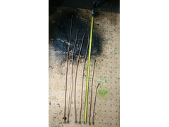 
RigidToFlexi
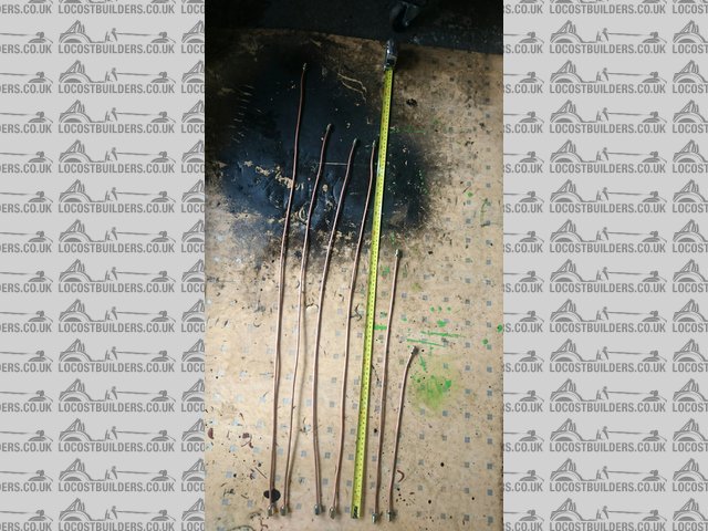
Also, I assumed that the very shortest pipe was to connect between the clutch master and slave cylinders. By a process of elimination, the pipe I am
holding here is the one to connect the master cylinder to the T-piece, and as you can see, it is desperately short. Did anyone else have similar
issues?
TooShort
Cheers,
Mick
|
|
|
sdh2903
|
| posted on 9/7/16 at 03:33 PM |
|
|
To be perfectly blunt the best thing you can do with the mnr supplied brake pipes is chuck em in the bin. The lengths really didn't correspond
to where they were supposed to go. In my case they were all way too long. They are also made out of copper which will eventually work harden. I ended
up recycling all of the fittings and made my own pipes to the correct lengths using 3/16 kunifer pipe. Bit of a pain but better in the long run to use
kunifer.
|
|
|
micksalt
|
| posted on 9/7/16 at 03:43 PM |
|
|
quote:
Originally posted by sdh2903
To be perfectly blunt the best thing you can do with the mnr supplied brake pipes is chuck em in the bin. The lengths really didn't correspond
to where they were supposed to go. In my case they were all way too long. They are also made out of copper which will eventually work harden. I ended
up recycling all of the fittings and made my own pipes to the correct lengths using 3/16 kunifer pipe. Bit of a pain but better in the long run to use
kunifer.
Sounds like a plan.
|
|
|
micksalt
|
| posted on 9/7/16 at 04:07 PM |
|
|
Any recommendations on a good flaring tool? I assume we're double-flaring with it being brakes.
|
|
|
sdh2903
|
| posted on 9/7/16 at 04:28 PM |
|
|
Some are double flared, from memory into the bias valve and the bulkhead ends where the flexys connect.
I've had good success after a bit of practice with the laser hand held tool in the link below (you will get cheaper on ebay). The bench mounted
ones are better but more expensive. I've done a couple of cars worth with the hand held one with no leaks. Keep the copper pipe to make
templates as the kunifer is a bit harder to bend in situ. Also keep some to practice the flares. Might be worth also buying a pipe bender too.
https://www.machinemart.co.uk/p/laser-pipe-flaring-tool/
|
|
|
micksalt
|
| posted on 10/7/16 at 04:19 PM |
|
|
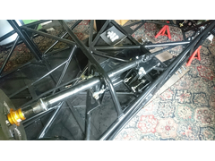
I wasn't intending to work on the car today, but got a bit carried away. I was a bit dubious about the fit of the steering column and associated
joints, so I thought I would do a trial assembly. After a bit of wriggling, it all seems to fit very nicely indeed.
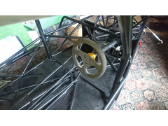 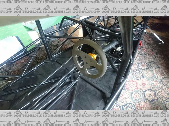
InstalledColumn
Detail of the column mounts.
 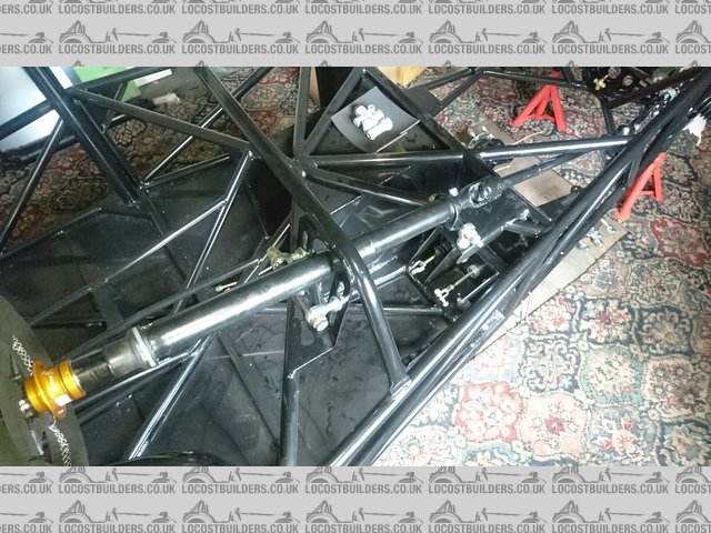
ColumnMountDetail
Detail of the bracket / bushing on the intermediate shaft. I'm not 100% on there being a plastic bushing with the column and rack having
ball-bearings. I might be slipping beer tokens to my tamed machinist to have something made with proper bearings and a metal body.
MidSupportBracket
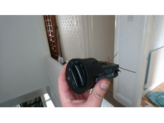
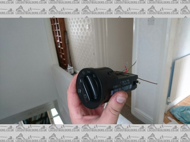
After doing some research on the IVA requirements for the fog light switch, it either required some ingenuity, or about £60 worth of electronics to
comply. Instead, this from a mk4 VW Golf seems to do everything I need using a mechanical interlock. I've tested it against the Golf wiring
diagram and it performs as expected, and will give a bit of 'production car' feel to the dashboard. The best part is that it was a mere
£4.75 (Part number 1C0941531), although you don't always get the wiring plug, which is very useful to have, particularly that the wiring
diagrams reference the plug numbers, not the pin numbers on the switch.
FogSwitch
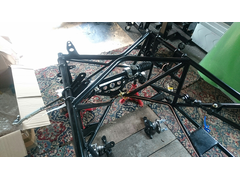
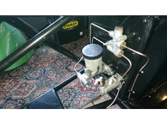
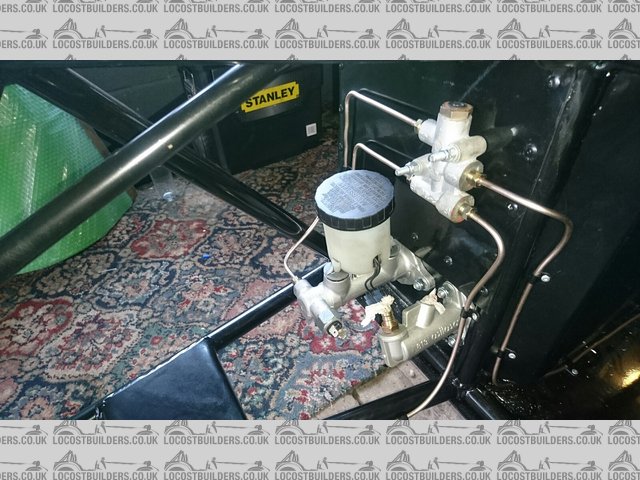
Since I'm making my own brake pipes, I am thinking of a departure from the default MNR layout. In the MNR layout, the brake pressure switch is
mounted underneath the proportioning valve. However, with the proportioning valve located above the height of the master cylinder reservoir, this
means that the switch needs to be removed to bleed the circuit - far from ideal.
DefaultBrakePipes
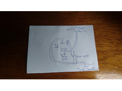
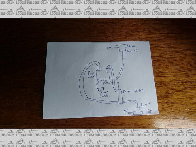
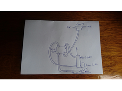
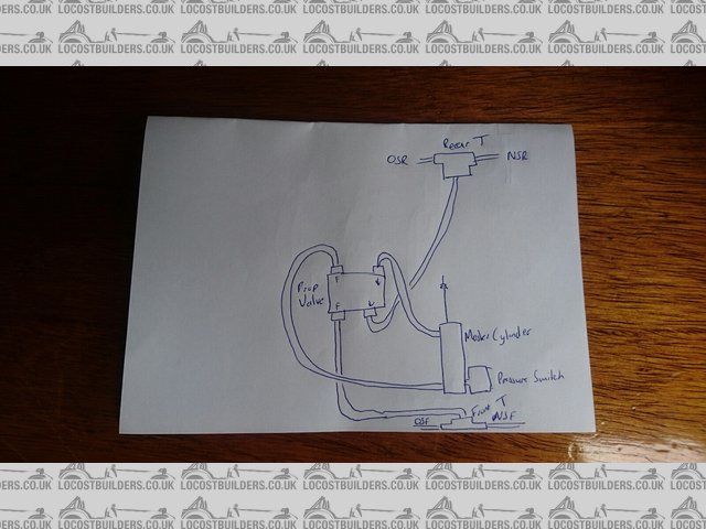
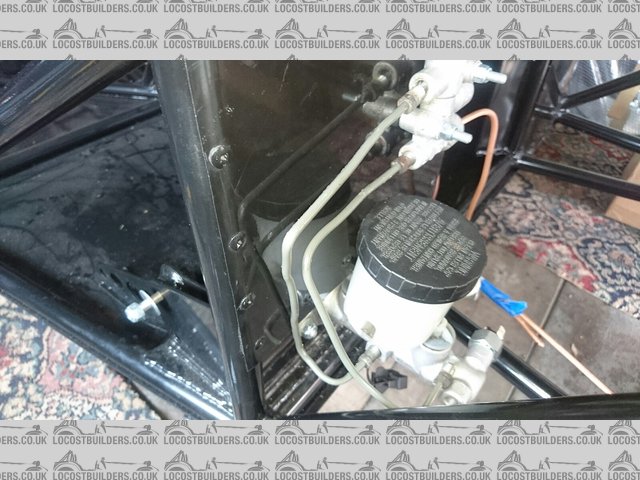
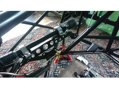
My proposed improvement is to mount the pressure switch directly off the master cylinder, below the reservoir height. By connecting the front brakes
via the proportioning valve, all routes through the proportioning valve end up at the caliper, where there is a bleed valve to pull any air through,
rather than dead-ends. Does anyone see any potential problems with this setup?
ProposedBrakePipes
Cheers,
Mick
[Edited on 10/7/2016 by micksalt]
|
|
|
sdh2903
|
| posted on 10/7/16 at 05:34 PM |
|
|
Ref the switch. I had it in the master cylinder as per your suggestion. I've seen a few other builds with it there too. Best place for it in my
opinion.
|
|
|
micksalt
|
| posted on 11/7/16 at 06:52 PM |
|
|
quote:
Originally posted by sdh2903
Ref the switch. I had it in the master cylinder as per your suggestion. I've seen a few other builds with it there too. Best place for it in my
opinion.
Excellent, that's the way I shall go then.
|
|
|
micksalt
|
| posted on 14/7/16 at 05:30 PM |
|
|
Lots of presents turned up today up today including all the tools for making my brake pipes. However, not a lot of time today so I just fitted the one
part.
BareMaster
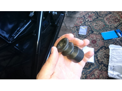 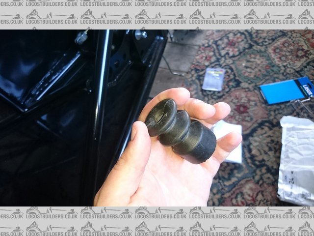
Gaiter
Available from Demon Tweeks, cost me less than a fiver.
ClothedMaster
I had read about a fellow Locostbuilder that got a stone caught in the master cylinder causing the brakes to bind, so i would recommend this.
|
|
|
jim87
|
| posted on 14/7/16 at 07:04 PM |
|
|
I originally had the pressure switch at the front, in the 3 way t piece, but changed it to the way you're going to.
You can make the MNR supplied pipes work, I think this is much neater
|
|
|
micksalt
|
| posted on 14/7/16 at 08:01 PM |
|
|
My issue with the MNR pipes were that the feed pipe to the front T piece was way too short. For the sake of a tenner's worth of kunifer pipe and
some tools I'll get to use again and again, I may as well make to measure.
|
|
|
micksalt
|
| posted on 15/7/16 at 05:19 PM |
|
|
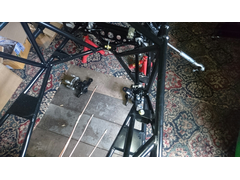
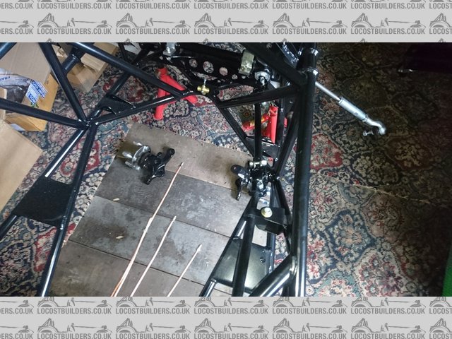
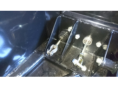
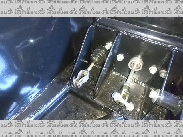
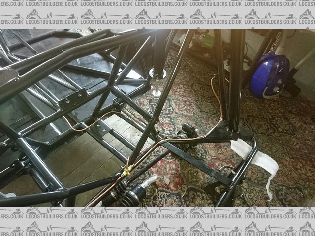
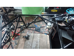
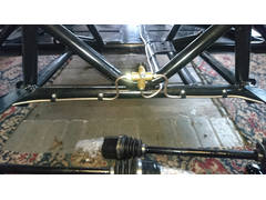
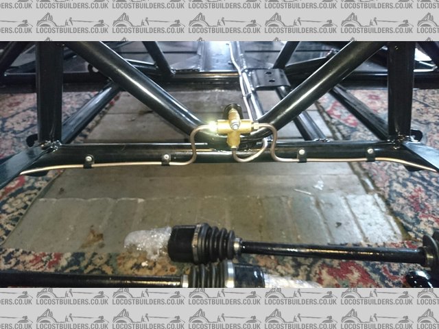
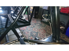
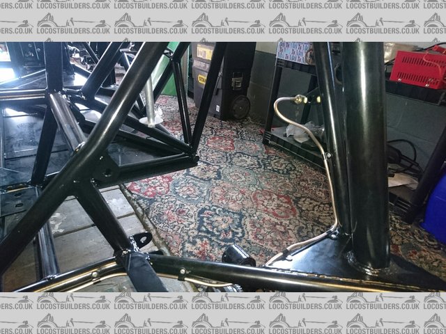
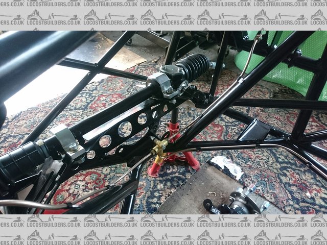
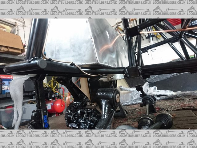
Before I commit to drilling holes and forming the kunifer pipe, please can folk take a look at the rough routing I've mocked up with the
original copper pipes and tell me if it looks right.
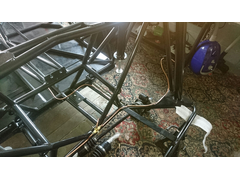 
RearBrakePipes
FrontFeed
 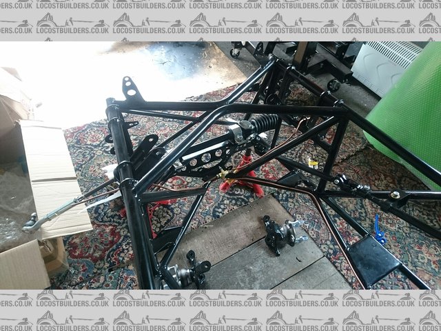
FrontPipes
BiasValve
|
|
|
micksalt
|
| posted on 19/7/16 at 10:31 AM |
|
|
Looks like I'll be making up my kunifer pipes to this pattern then this Friday. I'm going to get myself a nicer pipe cutter though,
I'm still nursing the blisters from Friday
|
|
|
jim87
|
| posted on 20/7/16 at 06:39 PM |
|
|
Looks very similar to the way I have mine.
Just be careful where you route around where the clutch slave cylinder will be. The clutch fork gets within an inch ish of the chassis tube when fully
disengaged
|
|
|
micksalt
|
| posted on 20/7/16 at 07:03 PM |
|
|
Cheers Jim, I'll try to keep the vertical hoses as far too the offside as I can get them.
|
|
|
micksalt
|
| posted on 26/7/16 at 08:35 AM |
|
|
First of all, this tool was an absolute joy to use. I had never made a pipe flare in my life, and yet using this tool, I did a whole car's worth
without a single bum flare.
 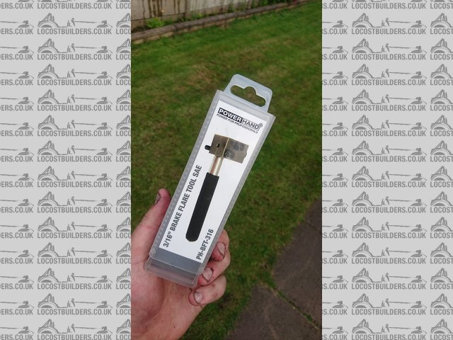
Powerhand
And here is the first pipe, double-flared at both ends this time.
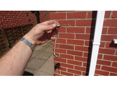 
FirstPipe
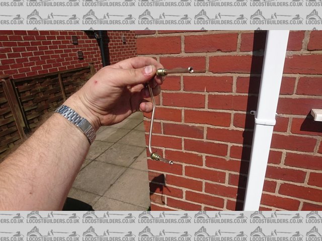
I decided that because the diff sits quite high, the best route for T-piece feed was this way. It was double-flared at the bias valve end,
bubble-flared at this end to match the T-piece.
RearT
And to the rear flexis. I think I need to neaten this up to make sure that there is less than 6 inches of unsupported pipe. This was bubble-flared at
the T-piece end, double-flared at the flexi end to match the profile.
RearBrakePipesFixed
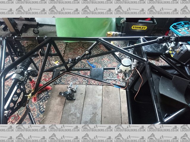
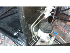
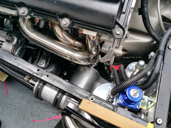
Very chuffed with the plumbing around the master cylinder and bias valve.
BiasValvePlumbed
And to the front flexis. Remember, bubble-flare at the T-piece, double at the flexi.
FrontPipesFixed
I didn't take a picture of this, but I had enough kunifer left over to make a generous length of clutch pipe. I had forgotten to note what style
fitting was at the Wilwood master cylinder end, so had to take it off to check. Turns out it is bubble flare at the master cylinder, double flare at
the slave. The reason I have made this longer than necessary is to put a loop in like the original MX-5 pipe to ensure that the pipe can accommodate
relative gearbox to chassis movement.
|
|
|
l5tuy
|
| posted on 27/7/16 at 10:59 AM |
|
|
Very nice Mick.
Where did you buy the flare tool? Is it a hand one or vice?
Stu
|
|
|
micksalt
|
| posted on 27/7/16 at 11:05 AM |
|
|
It's a hand-held one, although I suppose there's nothing to stop you slipping off the neoprene sheath and clamping it in a vice if
required. I got it from Brake Pipe Flaring Tool Powerhand PH-BFT-316 3/16" . It's by a company called Powerhand, and
made in England, so you'll be doing your bit to prop up the economy . It's by a company called Powerhand, and
made in England, so you'll be doing your bit to prop up the economy
[Edited on 27/7/2016 by micksalt]
|
|
|
micksalt
|
| posted on 3/8/16 at 08:02 AM |
|
|
Sorry for the lack of updates folks, ended up giving myself sciatica by sitting on the garage floor for too long. Did a stint volunteering at the
local heritage railway instead which seems to have sorted my back out. Should be installing fuel pipes and fitting the pedals to their cylinders this
weekend. I've found a guide for fitting the pedals to make sure it is optimised for hee-and-toe, but at 6'3" tall I might optimise
the pedal positions for leg length as the priority.
|
|
|
micksalt
|
| posted on 8/8/16 at 07:43 AM |
|
|
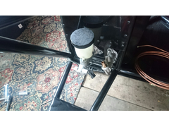
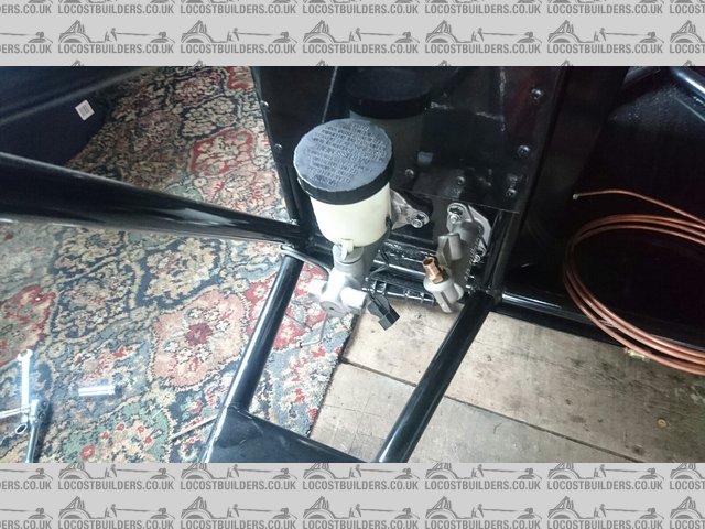
Before I do anything daft...
FuelPumpSide
In the build manual, the fuel pump is mounted on the nearside, on the chassis turb that carries the rear lower suspension brackets. However, looking
at my fuel tank, the outlet is pointing towards the offside, suggesting that the fuel pump should also be mounted offside. Please can fellow MX-5
based builders confirm? Any pictures of this area would be greatly appreciated.
Also, how does the fuel pump attach to the hoses? At the pump inlet end, it seems that I need a 10 mm bayonet to M18 thread adapter for connecting the
rubber hose between the fuel tank and the pump, which seems easy enough. However, the outlet end of the pump has a very strange fitting, the same as
this pump from CBS. I assumed that I just attached a small length of
rubber hose between this outlet and the end of the copper fuel pipe. However, this outlet has weird holes around the stem. Is there a specialist
adapter I should be aware of?
Cheers,
Mick
[Edited on 8/8/2016 by micksalt]
|
|
|
40inches
|
| posted on 8/8/16 at 08:04 AM |
|
|
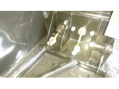
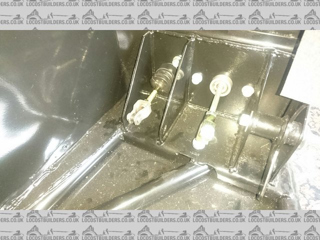
The pump uses a banjo fitting. I got one of eBay for about £5.
Best photo I have, but I think you can see it OK?
Description
|
|
|
micksalt
|
| posted on 8/8/16 at 08:16 AM |
|
|
Thank you very much, I see it now, I need a 12 mm banjo, copper washers and cap nut similar to
this, but probably cheaper from eBay (I need to check my fuel hose ID. Very
good.
Actually, I'm struggling to find the inlet end now, I thought that an M18x1.5 male thread to 6/8 mm ID hose tail would be reasonably common, but
my searches are drawing a blank
|
|
|