
IRS AGAIN!!!
chunkielad - 31/1/05 at 09:51 AM
Well then lads and lasses (are there any females on here?
Has anyone actually set up an IRS back end? I know it's going to be hard to set up (God knows I understand the problems) but I just want to see
if anyone has set up a WORKING and correct IRS on a Locost style frame (i suppose Tiger etc would work too) and what the setup and measure ments were.
Mainly just interested for knowledge but may well have a go at it.
locoboy - 31/1/05 at 11:11 AM
Chunkielad,
Photo deleted !
[Edited on 18/4/05 by locoboy]
chunkielad - 31/1/05 at 11:23 AM
Don't want to sound funny or anything but - does it work? Have you tried it out on the road yet? I want to try an dtake dimensions of someone for
set up, wishbones etc for a WORKING IRS that has no serious handling problems. I know this can be a very difficult this to setup.
PS I would preferable like a Sierra width version - none of that MG, Lotus, other wonderfully unusual setups!! I already have sierra diff and shafts!
locoboy - 31/1/05 at 11:35 AM
Dream on! Not on the road yet, it was bulit by Triton Racing and came with wishbones and uprights to fit sierra back end.
So there is more chance of it working than if it was designed and biult by me 
I Can post wishbone dims if you want when i get a chance?
chunkielad - 31/1/05 at 11:52 AM
The main data I need mate is the location (distance from side of chassis) of the support bars (Diff location and wishbone support) the layout of the
wishbones and a drawing of the hubs (which I assume are custom made).
I hope this isn't asking too much. I really want to try and make as much as possible myself (when my welding is up to scratch!) so ANY and ALL
measurements would be a fantastic help.
Ofset, castor, camber etc are needed too if you have them.
I have plans for a second car already but it's a little more unique to the locost!! I haven't even started this one yet!!!
locoboy - 31/1/05 at 12:17 PM
Will see what i can do, it may have to wait until the weekend for the chassis measurments because the chassis is under cover outside and its dark when
i get home from work!
The bones i can measure no probs.
The bones have rose joints on the outer ends so you can set toe in/out and camber to suit.
The measurement on the bones will be as accurate as i can make them but it doesnt really matter because they are adjustable for length with the rose
joints in so a mm or 2 is neither here nor there - so long as it +2mm not -2mm
Mix - 31/1/05 at 12:20 PM
I have the dimensions I'm using on a book width chassis but like Col, it's untested yet. If you can read either Turbocad or Autocad I could
cobble together some drawings when I get a minute.
Mine uses the IRS from an XR4x4i.
Mick
chunkielad - 31/1/05 at 12:21 PM
Sounds great fella - I keep asking for trouble on this one don't I?
I just have a feeling that this is going to cause a better vehicle in the end. Puls if I don't use it niw, I will defo use it on the new one.
Bob C - 31/1/05 at 12:28 PM
Another still building... but you can checkout photos in my photo archive and on www below. I've used mx5 uprights so my geometry is different to
everybody else, but the dimnsions are all on the website if you want to do the same.
BTW there are stacks of MK indy's on the road already with irs
Bob C
Hellfire - 31/1/05 at 05:12 PM
Ours for a start - if you need any pictures let me know! Just starting to re-assemble the rear... again! 
chunkielad - 31/1/05 at 05:14 PM
Defo pics and as many measurements as you can Hell fire - I really want to try this - what's the worst that could happen?
Oh hang on you crashed yours!!
Vet Will - 31/1/05 at 06:43 PM
Sorry to ask what is probably a really stupi question, but why are the rose joints on Bob C's set up horizontal, not vertical? I guess there is a
really simple answer to this.
Thanks Will
chunkielad - 31/1/05 at 08:19 PM
If I use a pair of wishbones at the rear, am I right in thinking that there is no need for any links or anything else of this sort?
JoelP - 31/1/05 at 08:34 PM
bob has his roses that way round cos they have enough flex to take it, and they are not prone to popping out under braking like they would be the
other way round. 
Bob C - 31/1/05 at 09:48 PM
JoelP nailed it in one - I would have put them the other way round but was pursuaded by the arguments set forth in this very forum!
Cheers
Bob
Alfalfameister - 1/2/05 at 09:24 AM
I haven't actually started my chassis, but I'll be following this thread closely. I have a preference for the live axle because that's
"by the book" and should make less of a hassle. But the de dion is enticing.
Since I plan to make it a track day car, I am scared about having an IRS (or rather, an IMPROPERLY designed IRS). But since the roads of my country,
are, well, 3rd world (potholes and general lack of smoothness), the IRS looks very tempting.
I have some nice books that I am trying to pore over: Chassis Engineering by Herb Adams, Staniforth's Suspension book, some of Carrol
Smith's (Tune, and Engineer to Win), and even a Steve Smith book(let) on suspension. After a few pages though, the headaches it gives me is
overwhelming. Heheh.
So, chunkie, thanks for starting this thread. By the time I get to my build, I hope all the other guys have contributed a lot to this thread.
BTW, since MK already has IRS, can't someone just post the dimensions for all of us? Or would MK get upset about this?
Cheers!
chunkielad - 1/2/05 at 10:41 AM
MK are VERY helpful mate but I don't think they'd approve of their design being half hinched!!!!
Glad to be of service though!! If my stupidity and ignorance can help, I'll stay that way for a while!!!
I'm sure someone on here with a working car will bob out and get the tape measure out in the next few days though!!!
Alfalfameister - 1/2/05 at 12:19 PM
quote:
MK are VERY helpful mate but I don't think they'd approve of their design being half hinched!!!!
Well, it's not like they're giving us the blueprints, or that we're doing it for mass production -- else, Caterham would be suing all
of us, eh? So maybe someone can take pictures of it and put some tape measure(s)/ruler(s) beside it, and we can work it out ourselves. Don't see
anything wrong with that.
quote:
Glad to be of service though!! If my stupidity and ignorance can help, I'll stay that way for a while!!!
Godz, that was funny!
pbura - 1/2/05 at 12:38 PM
One of the ways I've been burning off frustrated Locost-building energy has been studying suspension design. Resources have been pretty much
those cited by Alfameister plus everything I could find online. I've assisted a few builders by helping to set up computer models and working
through some modifications, but generally there were some compromises because chassis were already built.
Some conclusions I've reached in my research and tinkering thus far:
--Were it not for the ability to deal with bumps, a solid rear axle would be preferable because: (A) most obviously, squat in acceleration will cause
some camber change with IRS; (B) in independent FRONT suspension, KPI and caster work together to keep the wheels upright in turns, which doesn't
happen at the rear, and (C) forces generated in cornering travel along paths from tire contact patches to the instant centers of the wishbones, making
the inside wheel want to lift. This last point is true for any wishbone suspension, even the book front suspension, and the effect is usually
minimized by keeping the roll center under about 80mm.
--With a maximum height for rear roll center being ideally no more than about 75-80mm, the front RC must now be lower, say about 30-35mm, to maintain
a typical sort of roll axis. This necessitates a re-do of the book front suspension layout, which has an RC of about 75-80mm.
--Now that the roll axis has been lowered, the car is going to need more roll resistance than a book car, unless more body lean is acceptable.
Stiffer springs are pretty much out, so you are now looking at anti-roll bars front and rear. The use of anti-roll bars is somewhat detrimental as
they transfer some additional load from the inside tire to the outside.
--As far as specific goals for camber change, can't really say because intended use of the car rules the decision. Generally, people go with
more camber change in bump (and less in roll) for the front because it's doing the work of steering, and vice versa for the back, for the job of
accelerating. Because of the aforementioned steering effects, I've found that getting a pleasing setup for the front is fairly easy, but the
back is much less satisfying because of the compromises involved. My personal goals for camber change are .5-.6 degrees per inch of bump for the rear
and .75-.85 for the front (similar to book).
Despite the case against IRS for hard-core track performance, I still want to build it because the car will mainly see service on bumpy roads. Also,
I want to use cheap motorcycle shocks front and rear, and cannot think of a way except with IRS. There are some pics in my archive of a chassis
I'd like to emulate. Please ignore the ones with a plus (+) sign in the names as I can't delete them.
Pete
phelpsa - 1/2/05 at 02:21 PM
I'm making an IRS setup based on the Stuart Taylor designs.
It uses shortened driveshafts but I can get some dimensions if you want.
Adam
chunkielad - 3/2/05 at 12:53 PM
I take it that from the distinct lack of response including measurements, I'm not going to be let in on the trade secrets!!!
Someone must have a set of measurements for their IRS on Sierra width. Anyone? I only need the wishbones, hubs and where to put the members (metal
ones not the people on here!)
Cheers in advance.
locoboy - 3/2/05 at 03:45 PM
patience young man!
Wait till the weekend and i can give you the chassis dimensions - if it aint pissing down!
And i can give you the lower and upper bone dims tonight.
chunkielad - 3/2/05 at 04:35 PM
Not good enough col!! Get out there in the rain and earn your wage!!!
Sorry - I keep wanting to do bit then stop myself as I don't have all the info - then get stressed because I've done nothing!!!
Maybe I need to finnish my attic quicker and I can get welding some more - a bit of welding practise would get me a lot further than these
dimensions
Mix - 4/2/05 at 09:25 AM
Heres a few of the figures I'm working with to be going on with:
Sierra width from outer face of hub carriers 1391mm
Lower wishbone length 462mm
Distance between lower wishbone mounts 418mm
Distance between upper wishbone mounts 679mm
Upper wishbone length 308mm
Upright height 255mm
SAL 2540mm
Camber change C .5 degree per 25mm bump or droop
Vertical separation beween upper and lower bone inboard monts 224.5mm
All of the above refer to the rear suspension.
Mick
[Edited on 4/2/05 by Mix]
James - 4/2/05 at 09:51 AM
Chunkie,
What about buying a GTS or MK DeDion system? That way you'll get something that you know works.
HTH,
James
chunkielad - 4/2/05 at 10:07 AM
I also get something that costs me more money than I have
Thanks for those measurement mate - VERY useful. I can make a start on design and jigs from there.
chunkielad - 5/2/05 at 11:20 PM
Found these images - anyone tell me if these measurements are similar to ones used on the road at the minute? I don't want to work to settings
that will cause problems.

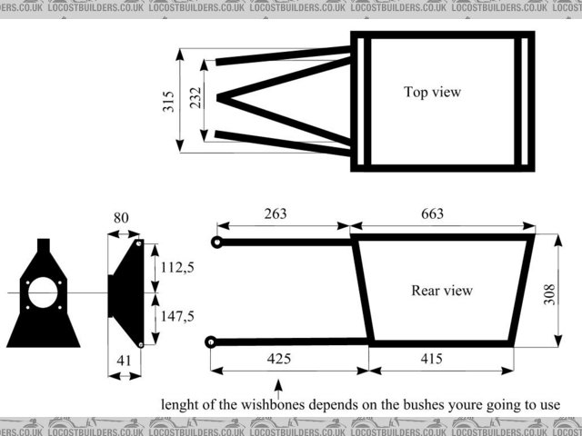
Rescued attachment REAR.jpg
chunkielad - 5/2/05 at 11:21 PM
Also chassis layout - I will work out if these are to scale before using them but I think they are....
chunkielad - 5/2/05 at 11:22 PM
If the person who owns these files is on here, please U2U me I can't find who they belong to.
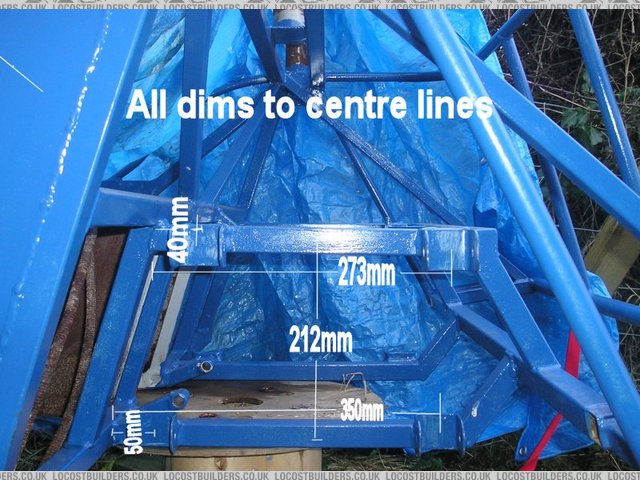
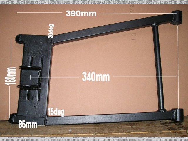
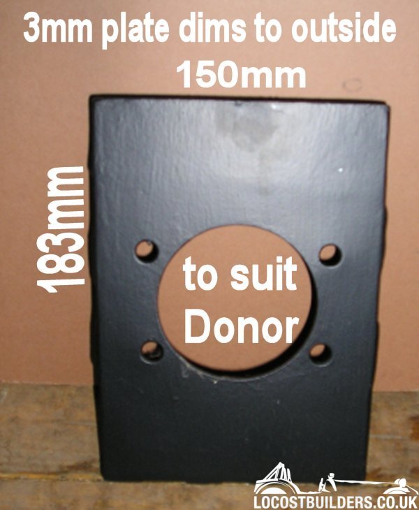
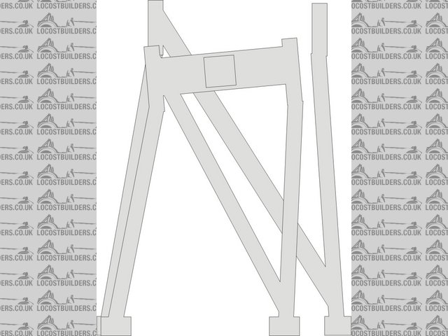
locoboy - 6/2/05 at 06:15 PM
Picys of IRS on book chassis
with Dimensions on for you.
As accurate as i could be with a tape measure.
Lower bonw


bottom bone dims
IRS Rear view


irs dims rear view
IRS side view

irs dims side view
Top bone

top bone dims
upright


upright dims 1
Upright
Hope thats of some helf for you.
[Edited on 18/4/05 by locoboy]
Bob C - 6/2/05 at 08:05 PM
Hi Colmacol - please don't take offence, but your bones look like they could use the odd triangle in 'em to prevent "lozenge"ing
when you hit a kerb or pothole.
Likewise the box they're hung off - (though it seems to work OK in tiger avons!) + I'm only too well aware of the difficulties in making
something you can get the diff in and out of!
I'd feel happier making sweeping statements like that if my car had been on the road a few months already - but I'm just venting an
unsubstantiated 1st impression here so feel free to shoot me down in flames!
(hah! as if you wouldn't....)
all the best
Bob
britishtrident - 6/2/05 at 08:29 PM
For a proven lower qwishbone here is Spyders version of the original Lotus Elan Plus2 wishbone --- they are just an easier to make skightly beefed
up version of the Lotus original --- both Spyder and the original Lotus wishbones have passed the test of time note the diagonal which as Bob C
very rightly pointed out is there for a very good reason. http://www.spydercars.co.uk/CB-PG3_PLUS2_LR_WISHBONES.jpg
The reason for the dog leg is the Elan had semi-inboard rear discs ie mounted on the inboard of the strut.
The top wishbone only requires to be a simple triangle with a single rose joint or bush at the outer end --- using two bushes or rose joints will
over locate the upright and could cause problems.
[Edited on 6/2/05 by britishtrident]
[Edited on 6/2/05 by britishtrident]
chunkielad - 6/2/05 at 08:44 PM
THANK YOU VERY MUCH GUYS!!!!
Wow what a comprehensive set of figures Col. That's got everything I need to have a go and I THINK I will be able to get my engine above all this
too.
It's time to get working and no more talking I think!!!!
locoboy - 7/2/05 at 09:17 AM
quote:
--- using two bushes or rose joints will over locate the upright and could cause problems.
Over locate - what does that mean?
chunkielad - 7/2/05 at 10:57 AM
Could you double check your figures for me COl? I started drawing the wishbones based on your figures and using the angle and measurements you gave,
It doesn't fit. Sorry
locoboy - 7/2/05 at 11:02 AM
I measured the angles roughly bsing a protractor pmsl.
I will recheck tonight for you.
The angle is not that important its the overall length that is, the angle is only there to allow it to clear the outer most tubes.
chunkielad - 7/2/05 at 12:29 PM
Using the pictures and sizing up I got these.
The don't seem right at the Hub end - any ideas?

Rescued attachment IRS Setup.jpg
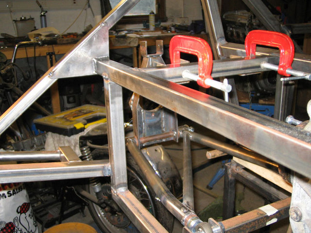
Mix - 7/2/05 at 12:38 PM
Some very amateurish pics of my IRS to date:


Rescued attachment IRS-3.jpg
NS Dev - 7/2/05 at 12:42 PM
Personal statement here, and it aint the only answer I know, but if I hadn't cheated and bought my chassis from Stuart Taylor, I would have gone
for a De-Dion setup. I just prefer the characteristics of this setup, for a start the chassis will be lighter than with an IRS setup, in fact De-Dion
gives the best weight saving potential of any setup, as well as very good roll control.
I bought my stuff ready made because I have too many other projects to do. If I were to make another chassis in the next few months it would be
another grasser, the sevens are too cheap to just cheat and buy!!!
So I have ended up with the ST chassis and IRS which generally looks ok. The wishbones are pretty "minimal" in terms of build quality, but
look ok and the geometry appears (to me at any rate) to be fine with no glaring errors (like some other manufacturers!)
Mix - 7/2/05 at 12:42 PM
Can't seem to get more than one attachment per post

Rescued attachment IRS-2.jpg
Mix - 7/2/05 at 12:42 PM
Last one


Rescued attachment IRS-1.jpg
locoboy - 7/2/05 at 12:49 PM
Chunkie,
Try flipping the top bone over. They are handed.
Like i said i will re measure it tonight and *try* to be a bit more accurate!
chunkielad - 7/2/05 at 12:52 PM
Those pis are fantastic mate but I'm looking more for dimensions thanks though. I've looked at Dedion and decided I really want to make IRS
work. There are lots of companies out there with working IRS systems and I can't see why I can't do it too. The car I am building is
designed for the road and track and I think IRS properly set up will give the best ammount of adjustment to setup for either.
I'll let a little secret out in that I am trying to get a custom car built with the option of selling it at a leater date as a turnkey or kit. My
first one will be built by me but I have a few companies lined up ready to make bits as needed after jigging it all up. The chassis is based around
the McSorley but is a middy BEC (will eventually be midddy car engine option too). The body work hasn't quite been finalised just yet so not
going to let too much out of the bag.
If I can offer IRS and maybe a DeDion option, I could give the best option range to customers. I want IRS working on my car before I offer it though.
I have absolutely no knowledge of suspension and hence need a smuch info as possible to ensure I don't sell anything duff or even worse
DANGEROUS!!!
Mix - 7/2/05 at 12:58 PM
As I've built it all myself I have all the relevant dimensions. The most important ones I posted earlier in this thread.
Do you intend to design your own IRS or just make a direct copy of another, (perhaps untried) design?
Mick
britishtrident - 7/2/05 at 01:05 PM
quote:
Originally posted by colmaccoll
quote:
--- using two bushes or rose joints will over locate the upright and could cause problems.
Over locate - what does that mean?
A linkage should alwaysuse the minimun number links to do the job adding any extra links and the result will be a conflict of arcs -- it may be
very slight but even that will cause additional streses within the system and could cause the linkage to bind up particularly if there is no designed
in compliance such as rubber bushes.
In a double wishbone system if the upper arm is in the shape of a letter "A" then a lower arm in the shape of a letter "N" will
provided restraint in all the required axis of freedom.
chunkielad - 7/2/05 at 01:07 PM
I'd prefer a known working set up so I can guarantee it works. This way I will have faith in it.
I don't want to be supplying something that isn't right. What did you do to get your measurements mate? Did you pick them out of the air or
was it a bit scientific?
britishtrident - 7/2/05 at 01:07 PM
quote:
Originally posted by Mix
Can't seem to get more than one attachment per post
Nice work Mix
A+ plus
Mix - 7/2/05 at 01:08 PM
That's comforting to know as I'm currently favouring an 'A' shaped upper arm
Mick
Mix - 7/2/05 at 01:14 PM
What did you do to get your measurements mate? Did you pick them out of the air or was it a bit scientific?
Read books, asked questions on here and taught myself the basics of CAD. Combined the ingredients and that's the result so far.
Mick
locoboy - 7/2/05 at 01:28 PM
quote:
Originally posted by Mix
That's comforting to know as I'm currently favouring an 'A' shaped upper arm
Mick
Get yourslef to the docs then quicksmart
Mix - 7/2/05 at 01:31 PM
Nah!!
S'OK it goes with my all singin and dancin rear end
Mick
chunkielad - 7/2/05 at 01:32 PM
I'm impressed Mix - I have not had a go myself yet as to be honest - I'm not sure I could get my head round it. Much easier to use a system
that works already
I assume yours isn't tested then. If the guys and girls on here generally say there's no probs, do you have an issue with me copying? I
wouldn't want to steal anything
Mix - 8/2/05 at 12:12 PM
Yes as yet untested.
I don't have an issue with anyone copying or adapting my design for their own use, (in fact it would be rather flattering), however I would feel
a tad peeved if someone used my work commercially without coming to some sort of arrangement first.
Mick
pbura - 8/2/05 at 12:36 PM
Nice job, Mick!
I plunked your coordinates into the Wishbone proggie (guessed at ride height and tire size) and you have very tight RC control (as you know!). Roll
center height I came up was 79mm, which might be off because of my assumptions. Camber gain was as advertised.
As your layout is about what I'd like myself, I'll be interested to see how it works out for you. AFAIK, it's much like the new
Caterham.
Did you make any changes to the front end?
Pete
Mix - 8/2/05 at 12:45 PM
At the front I kept the book design lower bone. The upper bone I redesigned increasing it's length slightly, (to decrease the amount of exposed
thread on the ball joint which I considered to be excessive). I also made it so that the brackets would sit centrally on the chassis members and give
me the correct degree of castor. Finally I incorporated a camber adjusting mechanism which, (I believe), is a refinement to the ones normally seen.
Mick
chunkielad - 10/2/05 at 10:56 AM
Do you have to build in castor and camber in the IRS too then? I do have a suspension book on it's way BTW so expect more questions to
come!!!!
chunkielad - 10/2/05 at 11:02 AM
Sorry camber is obvious!! Castor is the one I wondered - Mix where have you placed the mounts horizontally to get the right Castor?
MikeRJ - 10/2/05 at 01:43 PM
Looks like a nice setup Mix, I like the uprights especialy. Was it originaly designed for bushes rather than rod ends? Just wondering why you bent
the lower wishbone tubes at the chassis end?
Also, whats the deal with what looks like a nut hanging off the end of the lower upright bolt?
[Edited on 10/2/05 by MikeRJ]
Mix - 11/2/05 at 09:26 AM
Mike
I designed the uprights with ease of manufacture in mind and was quite pleased with the result although I still have to finalise the positioning of
the coilover attachment. I decided to go for some form of adjustability early on and opted for rose joints which I thought would be best mounted at 90
degrees to the axis of movement of the wishbone, hence the bends in the wishbones at the chassis end, (the upper bones which are still in the design
stage will also incorporate adjustability. Hopefully this will allow me to tune the suspension for optimum ride/handling.
Chunkielad
As you'll probably have realised I'm no suspension expert, all I've done is asked questions and read books, I don't think I'm
qualified to advise on suspension issues other than to explain what I've built and why I built it that way. Others on here know much more than I.
Good luck with the reading and don't get too bogged down in the early stages.
Mick
New I'd missed something, (I can't switch between the topic and the reply window)
The nut is nothing to do with the set up it's just a threaded rod temporarily holding the wisbone and upright together,(it's actually part
of a jig I made to make my front upper bones)
[Edited on 11/2/05 by Mix]
WIMMERA - 11/2/05 at 10:43 AM
I've gone the other way Mix and put the rod ends outboard with nylon bushes inboard top and bottom, the top bracket on the upright has a crush
tube through it with a rod end either side (4 in total) and the top inner bone bracket has three sets of holes for future reference. Interesting to
compare what others are doing.
Wimmera
chunkielad - 11/2/05 at 10:58 AM
Hey Mix,
all the info you have offered seems to be straight and true!! Your measurements may work, may not but at the end of the day, I'm sure it'll
be good enough either way unless you are racing.
Just got 'How to build & Modify Sportscar and Kit car Suspension and brakes' by Des Hammill and 'Car Builder's manual'
by Lionel Baxter - I hope I'll learn enough to prove or disprove your setup!!!
chunkielad - 12/2/05 at 02:06 AM
Just been reading 'How to build and modify Sportscar and Kitcar Suspension and brakes.' and got a LOT further to understanding
suspension.
So here goes... the standard FRONT book setup gives about 4-4.5 degrees of camber change (ignoring any connections but the wishbones and tested over a
4" change in height - 2" up and 2" down).
Would I be right in saying this is a good setup? - could the same setup be used on the rear? Same points of attaching to chassis and same wishbone
lengths etc...
I know you'd have to modify to fit Upright etc but basic geometry stays the same.
How would it handle? It seems from what I've learned so far that all would be fine. AND there is no steering to worry about at the back
obviously.
[Edited on 12/2/05 by chunkielad]
[Edited on 12/2/05 by chunkielad]
chunkielad - 12/2/05 at 02:53 AM
Could someone test these measurements for me and report if they are good or bad?
Upright Height 240mm
Upper Bone 263mm
Lower bone 425mm
Top bone chassis point 124mm in from Bottom one
Top bone chassis point 259mm up from Bottom one.
Chunkie - 13/2/05 at 08:15 PM
Anyone? I don't get the wishbone program at all - I designed this in 2d and theoretically I think it'll work but I'd just like someone
to double check the figures.


