
Bolt-in chassis braces?
Grant - 25/3/04 at 11:31 PM
Do these work well? Any tips on the size, strength and type of the fasteners used? Seems like 95% of kitcars out there have open engine bays (for
obvious reasons), and could really benifit from extra bracing.
The car I am thinking of building (eventually) is here:
http://www.aeonsportscars.com/
Unfortunately there aren't very many pics of the chassis online,
http://hometown.aol.co.uk/kezcurtstan/blue-front-what-it-looked-l.jpg
http://hometown.aol.co.uk/kezcurtstan/blue-front-what-it-looked-l.jpg
From what I can tell, the chassis follows all of cymtrik's points listed in his kitcaranalysis.doc, except maybe 3 and 4. I'm not sure I
understand exactly what he ment on those points.
If I end up building this car, I would want a lot of power, maybe an excessive amount. Its got to be faster than my old modified production car,
afterall  I guess a transverse engine would help the chassis cope with power better though wouldn't it?
[Edited on 25/3/04 by Grant]
James - 26/3/04 at 01:32 AM
Hi Grant,
Ned and I had a look at this at the Stafford kit car show- first thing that sprang to mind was- where the hell's the rear windscreen! 
You can't see bugger all out the back!
I didn't look under it at all- not sure if Ned had a look at quality of chassis etc. I seem to remember the GRP seemed pretty nice.
One thing that springs to mind from the chassis pictures you posted is: what a pity to do a new suspension design car and then fit Cortina front
uprights!  They're getting harder and harder to source- what on earth was gained by using them?
Also, pity they didn't go for inboard suspension when there 'appears' to be room for it.
As it happens they're right near the upcoming Detling kit car show (which they'll presumably attend) so a kind person here may take some
more pictures of it if you want!
Cheers,
James
Grant - 26/3/04 at 01:56 AM
quote:
Originally posted by James
Hi Grant,
Ned and I had a look at this at the Stafford kit car show- first thing that sprang to mind was- where the hell's the rear windscreen!
You can't see bugger all out the back!
Hah, I expect they didn't want the aerodynamic penalties of a cut-off back, like say the Noble M12. In theory the cut-off back would cause more
drag and lift. Works for me, I'll get used the side-view mirrors
quote:
One thing that springs to mind from the chassis pictures you posted is: what a pity to do a new suspension design car and then fit Cortina
front uprights! They're getting harder and harder to source- what on earth was gained by using them?
Ah, I didn't know what uprights it used. Thanks for this info. What were the rear uprights? There was some kind of problem between me and
Aeon's mailservers that has been blocking my emails, so I haven't been in contact with the company, only the 1 owner.
quote:
Also, pity they didn't go for inboard suspension when there 'appears' to be room for it.
Is there really much to be gained in a closed-wheel car? Other than a very slight decrease in unsprung weight?
quote:
As it happens they're right near the upcoming Detling kit car show (which they'll presumably attend) so a kind person here may take
some more pictures of it if you want!
That would be great!
[Edited on 26/3/04 by Grant]
britishtrident - 26/3/04 at 09:05 AM
quote:
Originally posted by Grant
Do these work well? Any tips on the size, strength and type of the fasteners used? Seems like 95% of kitcars out there have open engine bays (for
obvious reasons), and could really benifit from extra bracing.
snip
[Edited on 25/3/04 by Grant]
No point in using a bolt size that much exceeds the stregnth in shear of the chassis tube you are joining it to, the true shear strength will be below
the theorhetical value calculated. According to my calcs based on Locost style 25x25 rhs (making a lot of sweeping assumption) a 8mm (5/16" bolt
in double shear would be strong enough --- however a 10mm (3/8" would look more sensible, 11mm (7/16" is also be good.
bolt
in double shear would be strong enough --- however a 10mm (3/8" would look more sensible, 11mm (7/16" is also be good.
The bolt would require decent thicknes double shear brackets welded on to the tubes say 1.8 or 2mm thick and the bolts would have to be a close fit
in the holes a bit like proper " fitted bolts".
The length of the removeable brace should be adjustable because chassis flex when engines and suspension are fitted.
kingr - 26/3/04 at 12:55 PM
Grant,
My undestanding is that bolt in braces are only effective if they are incredibly precisely made and fitted - any freeplay and they're totally
valueless.
Kingr
Terrapin_racing - 26/3/04 at 02:42 PM
Remove all play by using SRE's at each chassis mounting point.
Photo shows part of 'Y' section crossbrace on rear engine bay of current project.
Done this many times with great success. Avoids the need to be deadly accurate with your mounting points and bar holes. Also looks the business.
cheers
Rob
PS: See Nick Skidmore (www.racecar.com) for very reasonable 3/8" unf SRE's - 3000lb rated rose engineering ones for peanuts - no good for
suspension , but ideal for this type of application.
[Edited on 26/3/04 by Terrapin_racing]

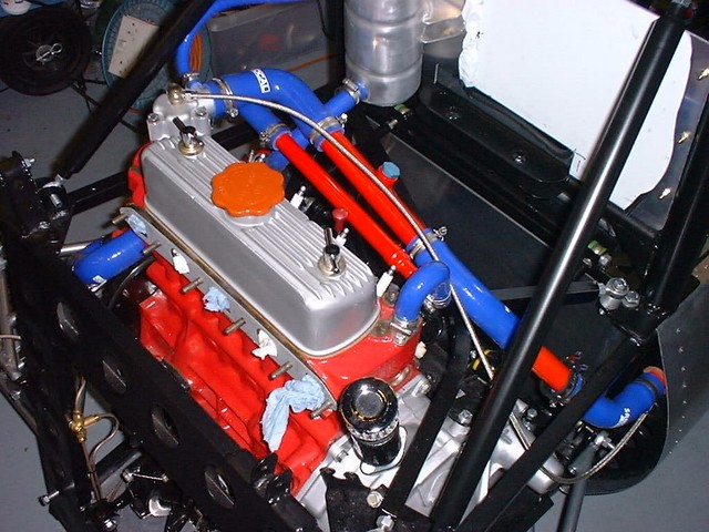
Rescued attachment eb4.JPG
GO - 26/3/04 at 02:54 PM
terrapin,
'scuse the ignorance, but SRE's? who are they then?
cheers,
Graham
britishtrident - 26/3/04 at 04:18 PM
A Rose joint by any other name.
Spherical Rod End bearings are called Rose joints after the manufacturer who supplied racing teams in the 1960s and 70s.
A very good simple way of doing it but not the only way.
GO - 26/3/04 at 04:44 PM
Doh!
Cheers britishtrident, temporary brain failure there. Could see what terrapin was on about from the pic, just couldnt remember what SRE stood for!
MikeR - 26/3/04 at 05:59 PM
<pssst>
Does anyone feel brave enough to mention to terrapin that he missed a bit when painting his block????
Grant - 28/3/04 at 08:28 AM
Spherical bearings, I should have thought of that! Thanks guys.
If he is reading this, I'd be interested to hear what cymtriks thinks of this idea, and the chassis in general (unfortunately those are the only
pics I could find).
From what I understand, it did undergo a lot of durability testing at MIRA. I am told they tested the suspension until failure (it lasted 1 and 3/4
"cycles", the average car only failing in the first cycle). Then they reinforced the suspension at the failure point.
I guess this was the machine used to test it?
http://www.aeonsportscars.com/images/mira/components_rig_test_large.jpg
from this page: (also seems to show some FEA software)
http://www.aeonsportscars.com/index.cfm?page=mira
[Edited on 28/3/04 by Grant]
Terrapin_racing - 29/3/04 at 08:09 AM
Missed abit - how dare you!
lolololol
Thats the machined surface on the head upper face.
MG Metro heads have two areas where this is exposed (ie part of the gasket face) - 0ne either side of cover.
I think it looks odd painted?
[Edited on 29/3/04 by Terrapin_racing]
