
I'm also getting more into SW too..;D
Check out the mid-engine section if you don't already....
Hi,
I wasnt sure where to post this, so here it is; i am just starting to fully model my car in solidworks, and i was wondering if it would be a good
idea to set up some sort of solidworks parts database, for things like hubs etc? Im building a midy with MR2 running gear, so most of my bits will be
of little use to most, but i would be happy to share.
Anyone have any thoughts on this?
Hey...sounds like my car..
I'm also getting more into SW too..;D
Check out the mid-engine section if you don't already....
Hi Alan,
well i was going to build a standard locost, but I had an engine already (1.6L Honda Vtec, 170bhp.) and they spin backwards, so middy was the
obvious way forward. I have taken a lot of comfort in the fact yourself and others are nearly there, and although not fully designed yet, i have made
most of the hardware decisions, and have most of the bits. So look out for a Alan B clone in the UK in a few years time!! 
MonkeyHunter,
I think that sounds like a great idea, but I'd have to be honest and say that it only sounds great because I'd love to model my car in
Solidworks but have never been able to get anywhere fast with it. If someone else designed all the parts for me then that might give me a fighting
chance of doing something constructive with it!!
I started messing with Solidworks when I started my build with the idea that I would design in CAD a few steps ahead of the real build. However, I
have never got beyond the first dozen or so tubes in CAD before I tied myself up in knots with mating conflicts (no funny comments please...) At this
rate my car will be complete before I've even got a basic chassis together in CAD... God knows how I'd get on trying to design somthing like
an upright or de-dion axle...
Anyway, enough of my failings as a CAD designer, I still think it's a good idea. I'm going to stick to programming and leave the graphical
stuff to those who can draw!
Cheers,
Craig.

quote:
Originally posted by craig1410
However, I have never got beyond the first dozen or so tubes in CAD before I tied myself up in knots with mating conflicts (no funny comments please...)
Yeah yeah, go on - have a good laugh...
I seem to recall you tried in vain to give me some Solidworks pointers a while back but as you can tell, it never sunk in. I was trying to build each
"tube" as a part with its ends cut at the angles specified in the McSorley plans but when you try to mate it all toether it never seemed to
quite fit. I think this may be down to the dreaded rounding/precision errors causing the mates to never quite mate up. I recall you had a clever
scheme of making each tube figure out where the cut points were by extending each one to the mating surface of the next tube but I couldn't get
my head around how this all worked. Any chance of sending me a drawing with a couple of tubes mated up in this manner? Let's say tubes
A1,A2,B1,B2 for starters? Of course, if you fancy sending me a copy of the entire chassis then that would be even better...
As for how such as "sharing" scheme would work I think there should be something in there to prevent people taking but not giving either
through incompetence (like me!) or sheer laziness. Old BBS's used to do this by having a ratio of downloads to uploads (say 3:1) to make sure
that you contributed at least one part for every three that you downloaded. Of course something like a whole chassis is a bit different to a
suspension bush but I don't think you want to make it too complex or it won't work. You also need to ensure that people don't abuse the
system by uploading garbage in return for good parts. If these parts were stored in a hierarchy by donor vehicle and/or category (eg steering,
suspension, chassis etc) with some sort of limited keyword search capability then I think that's all that is needed. It should also show the
author and perhaps have some form of "rating" to indicate the completeness/quality of the drawing.
How does that sound?
Cheers,
Craig.
Craig, which version of Solidworks do you have?
Later Solidworks packages has a weldments feature which enables you to place a particular size section onto a line and the trim the ends to other
sections in a number of different ways. If you don't have this it is a lot more difficult to produce models.
Dave
Dave,
Solidworks 2003 at present.
That may well be a useful feature if it does what you say it does.
Blueshift, is this the method that you were using?
Cheers,
Craig.
Ok, so we are agreed it would be a good idea then? Thats a good start
Im not sure it would be necessary to force people to contribute, in order to get parts. I imagine that that would restrict the speed that the parts
database grew, as if you were starting off designing a chassis, you would need to upload parts to get uprights for example, but at the beginning of
the design they would be unlikely to have any parts that were not available.
It strikes me that the people on this board, all have a common purpose, and it seems to be very friendly and free of the bickering etc, that occurs on
most other boards I frequent. I imagine that there would be very few people other than the members of this site, which would be interested in the
parts, so if access were restricted to members here than that should be enough. Those who can contribute and don?t mind sharing will, those who cant
contribute, can do so through the site in different ways by giving advice etc.
Though most people use the same major parts like uprights etc, it would be useful for everyone to have a selection of Rad?s to try out for example,
and as there is quite a variety being used, this is where I see the database becoming useful to everyone.
Scott.
Craig
I have recently upgraded to SW 2005. Its got some fantastic features such as the weldments also sheet metal work. Maybe you should upgrade aswell if
you use it a lot.
Dave
Scott,
Yes I agree with what you have said, it should indeed work just fine on the "honour" system and this can always be monitored and adjusted as
required. As for your mention of radiators, that is a very good point, I hadn't actually thought beyond the usual bits like chassis' and
suspensin parts. I have a VW radiator (the larger variant) and even my skills with Solidworks could capture the basic shape and extents of this part.
The same could be true for the likes of engine blocks and gearboxes although I would appreciate some guidance on how to get dims for such irregular
shapes without a 3D laser scanner.
One suggestion that I would make is that we make sure we stick to a particular version of SW and ideally create a template where the units of measure
are defined in advance along with any other useful settings. This should make interoperability easier.
Yep, count me in, I can now see how I can in fact contribute to the cause!
Blueshift, is it worth you speaking to Chris (Webmaster) to see how best the technical side could be put in place. It would be nice to just have a
link on the LB forum over to your co-hosted server with authentication info carried over automatically. Assuming of course that Chris is as keen on
this idea as we are...
Cheers,
Craig.
I am slowly building up my SW library, and currently have an almost finished McSorley +4 chassi and a de-dion assy.
I will be happy to share my files also.
Regards,
Chris.
quote:
Originally posted by craig1410
One suggestion that I would make is that we make sure we stick to a particular version of SW and ideally create a template where the units of measure are defined in advance along with any other useful settings. This should make interoperability easier.
Cheers,
Craig.
When you open an ealier version of a model it says that it will be saved as the new version which is fine for us. This propably means people with old
versions can't open our newer files
Dave
yes Dave, that is correct.
However, SW2004 cannot open files that are earlier than SW95 format. but I doubt anyone would have Solidworks from that long ago!
Regards,
Chris
Chris,
Fair point about the versions, I suppose we'll just have to make the best of it and see what happens. I still think that a standard template
would be worthwhile or at least a set of guidelines to enhance interoperability. Obviously some of you will already have models built but for any new
models this would still be worthwhile I think. Does everyone work in millimeters these days or what? Are there any standards about what is the top,
bottom, front and back of a model? (That's bound to provoke a few sniggers... ) What about angles - what is normally used as a reference for
cutting angles? (eg. if you cut a tube straight cross, perpendicular to its length, is this 90deg or 0deg?) That's the sort of stuff I mean.
) What about angles - what is normally used as a reference for
cutting angles? (eg. if you cut a tube straight cross, perpendicular to its length, is this 90deg or 0deg?) That's the sort of stuff I mean.
Anyway, you guys with Solidworks experience can more easily suggest how we kick this off, I am simply applying my generic project experience as an IT
Manager but maybe that's not appropriate here. (Exits stage left...)
Cheers,
Craig.
quote:
Originally posted by craig1410
Chris,
Fair point about the versions, I suppose we'll just have to make the best of it and see what happens. I still think that a standard template would be worthwhile or at least a set of guidelines to enhance interoperability. Obviously some of you will already have models built but for any new models this would still be worthwhile I think. Does everyone work in millimeters these days or what? Are there any standards about what is the top, bottom, front and back of a model? (That's bound to provoke a few sniggers...
Anyway, you guys with Solidworks experience can more easily suggest how we kick this off, I am simply applying my generic project experience as an IT Manager but maybe that's not appropriate here. (Exits stage left...)
Cheers,
Craig.
craig1410
I have been thinking more along the rad/engine/box/fuel tank and other components (bodywork?) line, as everyone generally builds one of a handful of
chassis, but all the other components mean that the permutations become quite large, i often see people asking which alt will fit in a certain space,
if we could have a few alt's modelled, then people could plug them in and see if they fitted. Obviously this sort of detail is not going to
happen over night, but if we could coordinate things a little im sure it wouldnt take us to long, and perhaps we could see some more elegant solutions
to space problems as a result?
Im still learning how to use solidworks (2003), but i can see that it is a very powerful tool and with a bit of time spent on it, could potentially
save people a lot of time on their builds.
Hi chaps. Thought I'd get the ball rolling, I have uploaded my current working set of solidworks files to my webserver. 7.5MB, includes +4
chassis and front suspension, cortina and GTS shock models, cut-out-and-keep tube templates, everything a young boy needs
Enjoy:
http://www.leetfighter.com/locost%20solidworks%20things.zip
Wow, we've just got broadband (last week) and I never knew how quick it was.
heh, it helps that that server is NOT on broadband but something a little quicker
my server at work is really slow at the moment, so when I download it, it terminates after about 10 minutes, and tells me that the D/L is complete.
I've managed to download 2MB, but the zip file is corrupted, so I can't actually access the files!
Gutted! I will have to wait for the server to sort itself out!
If not, I'll d/l it at home tonight.
Cheers Blueshift!
Regards,
Chris.
Cheers mate...looks good.....thanks for sharing
Very nice blueshift, cheers for starting things off; I cant open all the files though as i am using SW 2003 
I will contribute some stuff, as soon as i have a better grip of solid works, and some decent models of bits.
Um, you should be able to, I use solidworks 2003 as well. what can't you open?
I cant open the chassis with running gear, it says its an unrecognised file?
Oh, it works for me (obviously). can you open the chassis assembly? I wonder if your download was corrupted.. could try downloading again, if that doesn't work, maybe reinstall solidworks?
If its "chassis.SLDASM" then no i cant, i can see them both in the preview window though :/ i will try downloading and reinstaling, as
sometimes when i quit it crashes with an unhandled exception.
Scott.
If some one can u2u me with the info on where to upload... I have a small library of parts I'd like to share too, some basic wheels, hyabusa
engine model, a basic rendering of a 13b (rotary engine), shocks, nuts, bolts, a few human figures, some gears (chain drives), and a bunch of
imcomplete (i got bored before finishing them) items.
I am using 2004.
Also people who are using the older versions of solidworks can probably find the newer version on p2p sites like kazaa, their older authentication
codes should work on the newer version (at least that's what Ive been told). Ive been told that at least the '03 works on the '05
version, not sure how far back it will work. There might also be SW crack programs available on p2p sites such as kazaa.
It would also be nice to have a database of parts ex:
.....................Chasiss
..................../............
...........Frame............. Suspension
........../....................../........|........
Book............+4..... Front...Rear...Shocks
Then for each part
..........................Original
........................./.............
.....Modified by user A.......Mod by B
......../..................
Mod by C.........Mod by D
......................./.............
..............Mod by E........Mod by F
Sorry about all the periods, Ive never been good at ascii.
I would like to see a directory where each part that is original, my 13b for example which is quite unrefined, gets updated where a user can download
the model, then upload it with changes, having let's say 3 versions of the finished engine, each one slighly more finished than the last.
[Edited on 21/10/04 by derf]
quote:
Originally posted by derf
....Sorry about all the periods, Ive never been good at ascii.....
Nothing to do with american food additives then?
I have simple Rover V8, bellhousing and LT77 models. I'll upload them later if I remember.
well it looks like this might go somewhere useful  I better get modeling then!
I have some models based on mx5 running gear that I can stick on.
I've only modelled a rear quarter of the chassis so far so I'll build up a full chassis model & download that.
Bob C
If anyone has models they'd like to contribute, you can email them to me and I'll bung them up on a little temporary webspace until something cleverer is worked out.
Thanks for that Blueshift. Much appreciated!
Blueshift
I downloaded your .zip file and the extracted files look ok.
I'm totally "virgin" with Soliworks (I have 2003 ... not complete - no user manual).
How did you do the parts (tubes) and the assembly (chassis)? Parts first and then put together (how?)? or assembly first?
Can you give me some guidance? I might contribute a little if I manage to be able to work with the da.. thing.
BTW I have the correct dims for the balljoints.
jcduroc your best bet is to work through the online tutorials...
Uhm, do the solidworks tutorials first.
If others want to email me some things to contribute, jon at leetfighter dot com. I will put up a little blurb about how I made the chassis if I do a
little site for the files.
Basically though, the tubes are extruded squares, laid out with mates and using blind and extrude-to-surface, then fixed and the mates deleted (or it
got too unwieldy). I think all the mates are there to do an adjustable length engine bay though, should be possible to unsupress a lot of them and
float the front tubes and have a nice auto recalculating front end. A few red herring old mates in there though, so not super straightforward.
could i get a copy of the 13B model if possible. IS there a Turbo on it? If not any idea how much bigger it is with a turbo attached??
i need to figure out if a 13B T engine will fit into a Dax rush.
I spent a while adding my rear suspension to this solidworks model.
OMG the wheels are sticking into the chassis WTF....??? Ahhh - it's a +4 wide model.
Doh!!! - I'll bring it down to book dims eventually......... when I figure out how!
cheers
Bob
quote:
Originally posted by derf
If some one can u2u me with the info on where to upload... I have a small library of parts I'd like to share too, some basic wheels, hyabusa engine model, a basic rendering of a 13b (rotary engine), shocks, nuts, bolts, a few human figures, some gears (chain drives), and a bunch of imcomplete (i got bored before finishing them) items.
I am using 2004.
Also people who are using the older versions of solidworks can probably find the newer version on p2p sites like kazaa, their older authentication codes should work on the newer version (at least that's what Ive been told). Ive been told that at least the '03 works on the '05 version, not sure how far back it will work. There might also be SW crack programs available on p2p sites such as kazaa.
Is solid works anything like solid edge which is what i use?
quote:
Is solid works anything like solid edge which is what i use?
Cor, this topic brings back memories.
I think I have redone the front suspension since.
old old old old old old thread!
Only just signed upto this site a few days ago. I've finally got hold of solidworks 08 and was wondering how far everyone got with this parts
directory/database?
I had a quick look on solidworks' own website - they do have their own forums with a "Data Exchange" section which could be something
to do with swapping designs.
I don't know if it would be worth setting up a standalone "LocostDesigners.co.uk" forum with all solidworks parts/design discussion
etc?
Might be a bit extreme?
Just wondered
old thread indeed but i for one am interested in getting it rolling again, i have haynes rear uprights and bearing mounts etc, could use some engine drawings (pinto or 2l DOHC is what i really need- or zetec) if there are any solidworks people hanging around anymore!
quote:
Originally posted by hellbent345
old thread indeed but i for one am interested in getting it rolling again, i have haynes rear uprights and bearing mounts etc, could use some engine drawings (pinto or 2l DOHC is what i really need- or zetec) if there are any solidworks people hanging around anymore!

how does that hub stay on? im interested to know so i can see if i can redesign for a rear steer system? i need to know how the stub axle passes
through the bearing and is held on? thanks
alan
quote:
Originally posted by hellbent345
how does that hub stay on? im interested to know so i can see if i can redesign for a rear steer system? i need to know how the stub axle passes through the bearing and is held on? thanks
alan

Lets see if I can post more pictures.


As you can see the Ford design is a bit confusing, probably was a manager decision to get rid of a pile of stock.
The Caster is made to have a rear steering system but the installation and design at the car [sierra] was with a front steering.
To get a nice Caster with a front steering you need to rotate the hub by a lot.
[Edited on 16/8/08 by Cobra289]
[Edited on 16/8/08 by Cobra289]
This picture show the typical setup of a Locost.

After several evaluations we did decided to go in a different way, the Sierra hub don't give us the parameters that we want to have. The mushroom
piece should be changed in such way that would be result in a bad design.
But is our opinion, and we are quit stringent with our suspension design.
Regards,
Cobra289
quote:
Originally posted by hellbent345
i need to know how the stub axle passes through the bearing and is held on? thanks
alan

That SW dwg is far from correct. I've got a copy of the original Ford dwgs somewhere, I'll try and find them, but I know from dealings with
the original design team, the upright was always intended to be front steer, and front wheel drive. It just didn't end up that way.
I'd be very wary of turning the hubs around and rear steering the system, as well. I've seen it done, and the awful consequences.
The axle is held in with a big nut under the cover plate, sandwiching the bearings, which have a ridge between them in the main knuckle casting.
And again, these are made from SG IRON, NOT forged or cast steel.
Cheers,
Syd.
quote:
Originally posted by Syd Bridge
That SW dwg is far from correct. I've got a copy of the original Ford dwgs somewhere, I'll try and find them, but I know from dealings with the original design team, the upright was always intended to be front steer, and front wheel drive. It just didn't end up that way.
I'd be very wary of turning the hubs around and rear steering the system, as well. I've seen it done, and the awful consequences.
The axle is held in with a big nut under the cover plate, sandwiching the bearings, which have a ridge between them in the main knuckle casting.
And again, these are made from SG IRON, NOT forged or cast steel.
Cheers,
Syd.
On my Sierra 4x4 uprights the bottom and top balljoints are perfectly aligned. Are you sure that built in negative castor really exists? I
can't see why they'd do it that way as the production car is McPherson strut and the caster is determined by the rearward inclination of the
whole upright/strut assembly. Anybody got a real one to look at?
Liam
quote:
Originally posted by Liam
On my Sierra 4x4 uprights the bottom and top balljoints are perfectly aligned. Are you sure that built in negative castor really exists? I can't see why they'd do it that way as the production car is McPherson strut and the caster is determined by the rearward inclination of the whole upright/strut assembly. Anybody got a real one to look at?
Liam
so by the looks of that drg, the hub is kept from falling out by 2 thrust bearings, clamped onto an inner surface of the upright? the inside one
stopping it from falling outwards, the outer one stopping it from sliding inwards? ill draw a pic lol
also im not planning to turn them round, im planning to use rortys many posts to help design a new upright with good geometry and rear steer.. if i
can get it in the space available!
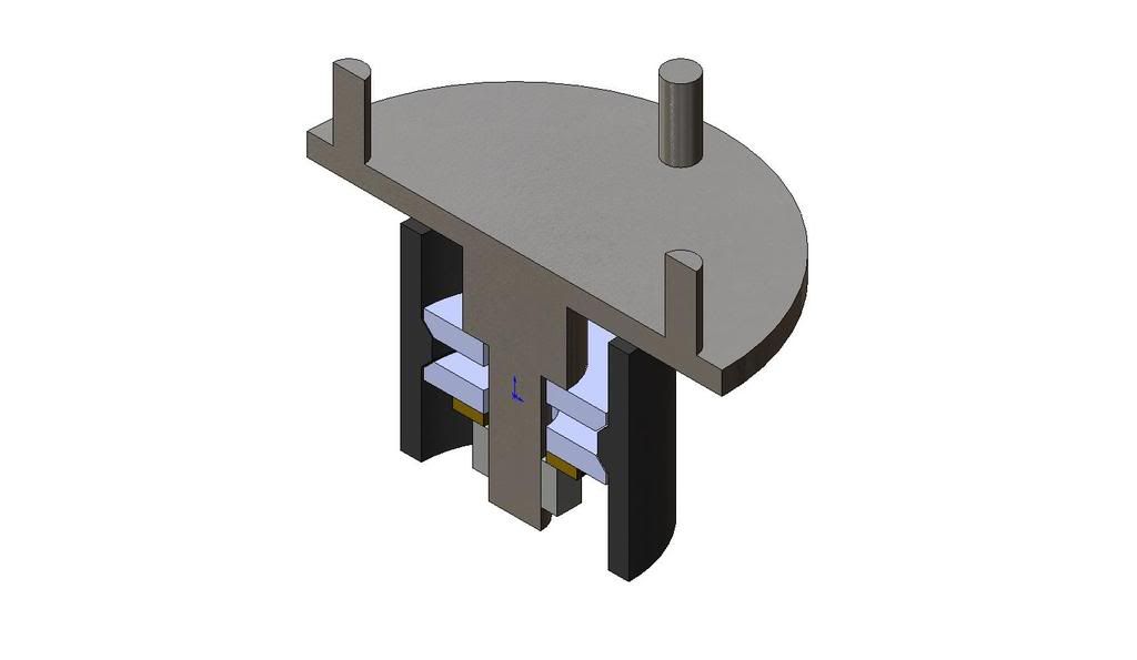
quick rough idea of what i recon the inside on an upright is like from the above comments and drgs, is it right? someone correct me if not
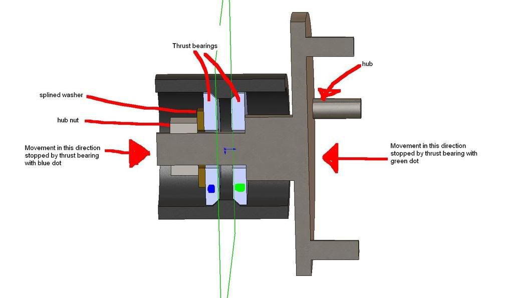
[Edited on 20/8/08 by hellbent345]
quote:
Originally posted by hellbent345
so by the looks of that drg, the hub is kept from falling out by 2 thrust bearings, clamped onto an inner surface of the upright? the inside one stopping it from falling outwards, the outer one stopping it from sliding inwards? ill draw a pic lol
also im not planning to turn them round, im planning to use rortys many posts to help design a new upright with good geometry and rear steer.. if i can get it in the space available!
quick rough idea of what i recon the inside on an upright is like from the above comments and drgs, is it right? someone correct me if not
[Edited on 20/8/08 by hellbent345]