
Inboard Front Suspension
AGK7 - 17/7/05 at 08:56 AM
Hi all,
I know this topic has been discussed to death and I have spent a lot of time reading through the archives but I have a few questions for the brains
trust.
The benefits of inboard front suspension seem fairly well accepted, less unsprung weight, progressive spring rates, and aerodynamic for what that’s
worth. I wonder why more haven’t had a go I’ve seen only a few locost clubbies who have tackled inboard shocks.
My thinking is as follows, try something that makes the car a little different and hopefully have a final product that also offers some more
adjustability. I am planning on designing a scale model of the push-rod and rocker as their movement is only in one plan this becomes quite straight
forward. My goals as I understand them are
1) Progressive spring rate
2) 1:1 ratio of wheel movement to spring compression
3) Push rod attachment near to bottom ball joint to avoid leverage
Whats the catch with attempting such a job, I am designing my bones to suit so I figure I might take it one step further. I am thinking the rocker
will be made from plate steel with rose joints on the push rod, the rocker pivot I am yet to finalise however I have noticed this set up
http://www.seven-nl.tk/
which looks nice.
So helps pleases, warnings comments on my design goals horror stories of those who have tried and failed/succeeded. I have also seen the Bob’s Locost
site which has help inspire this posts. Is it really that hard or have others just not thought it worth the trouble??
Thanks in advanced
Andrew
Australia
PS sorry for the long winded post 
scoobyis2cool - 17/7/05 at 09:34 AM
Hi Andrew, welcome to the site. Sounds like an interesting idea, I don't see any reason it couldn't be made to work in a 7 and as you say it
has a number of benefits over the traditional outboard design. (Having said that, outboard suspension is used on some of the best handling cars
around, such as the Lotus Elise, so it's not something to disregard completely!).
I was looking through Liam's photo archive yesterday - HERE.
He's made a nice looking inboard set up, maybe you could get in touch with him for some pointers. I'm sure other people have done it too but
I don't know who they are!
Good luck with the build, I look forward to seeing how it turns out.
Pete
JonBowden - 17/7/05 at 09:42 AM
I'd be interested in your results. I have little practical experiance in car construction (I've thought about it for many years but have
never had the space to try), but I believe one of your points may be a popular myth.
As far as I can see, if you use a 1:1 ratio of wheel movement to spring compression, you will not reduce unsprung mass, although some of the mass will
be on the other side of a pivot.
If you used a setup such that the spring/damper moved say half as much as the wheel (requiring a stiffer spring / damper) then this would reduce
unsprung mass.
craig1410 - 17/7/05 at 11:28 AM
Jon,
Doesn't the reduction in unsprung mass come from the fact that the shocker is working effectively "upside down" in an inboard design
where it is the lighter top section of the shocker which moves in reaction to suspension bump rather than the heavier bottom section? In a typical
outboard design the lighter top section of the shocker is fixed to the chassis (sprung side) and it is the heavier bottom section which is attached to
the unsprung side.
Could be wrong but this is my understanding unless someone points out the error of my logic.
Cheers,
Craig.
rick q - 17/7/05 at 12:07 PM
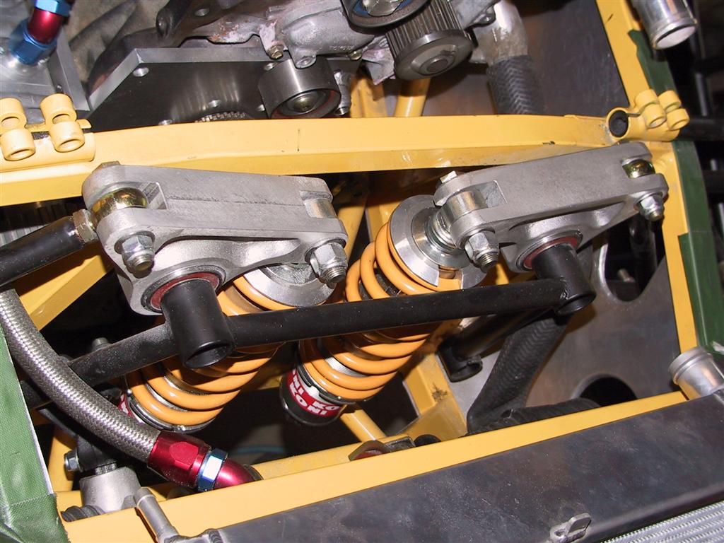
The Fraser (built in NZ) comes as either conventional or inboard front suspension. The rockers are available in a couple of different ratios in Cast
aluminium, though they should be relatively straight forward to fabricate in steel.
There are some good photos down at the bottom of this page :-
http://www.billzilla.org/fraser.htm
rick q - 17/7/05 at 12:09 PM
and here's the photo
JoelP - 17/7/05 at 12:29 PM
IMHO, the extra weight of the mechanism will outweigh any possible reduction in unsprung mass - the is both the mass of the pushrod and the rocker to
add on, and as craig says, having the shocker effectively upside down might save a few 100 grams.
The other three benefits as i see it are the slight reduction in the drag coefficient, the potential to change you effective spring rate just by
moving the rocker, and the fact that you can make the pushrod mounting point on the wishbone a little closer to the ball joint that you could with the
body of a damper in the way. Hence less bending force on the bones. 
Then there is also the small benefit of it looking quite clever, but that doesnt count for much.
However, i cant imagine it being hard to set up.
pbura - 17/7/05 at 04:34 PM
I'll second what Joel said about the pushrod and rocker adding to unsprung weight.
What I like about inboard shocks:
1. Can use cheap and plentiful second-hand motorcycle shocks.
2. By altering the rocker ratios, you can change the wheel rates of your springs.
3. Ride height can be adjusted with the push/pull rods.
The rocker ratios needn't be 1:1, but can be whatever you need to get the wheel rate you want.
Recommended reading: Allan Staniforth's Race and Rally Car Sourcebook.
JoelP - 17/7/05 at 05:19 PM
just thought, it could also be combined with the anti roll bar, if you wanted one, nice and tidy and all hidden. So thats one more possible benefit!

AGK7 - 18/7/05 at 03:25 AM
Thanks for the feedback guys.
Rick that is a lovely car indeed i trust you have no regrets about buying it!!
One of the benefits of a 1:1 ratio is it does make calc on wheel rates very easy.
I suppose a bit of it is wank factor but it would be nice to try something a little different. As mentioned ride height adjustment also becomes much
easier.
Any more links to design info or examples much appreciated.
Cheers
Andrew
rick q - 18/7/05 at 03:40 AM
Andrew - the links refer to Bill Sherwood's Fraser which is about to be registered. Mine is the red one in the avatar with a 16V 4AGE - just as
lovely though!!!
alfasudsprint - 18/7/05 at 11:23 AM
Take a look at the Caterham website, their all new CSR has in board front suspension.
smart51 - 18/7/05 at 11:33 AM
extend the top wishbone so that it extends inwards of the pivots. Use this extension to push down on your coil-over-dampers. No need to have push
rods. The extra weight is only the length of the extension bar (not much).
In terms of un-sprung weight reduction, all of the coil / damper is sprung. Better than that, the top of the damper moves in the opposite direction
to the wheel. Does that count as negative un-sprung weight?
Not having a push rod means even better aerodynamics.
NS Dev - 18/7/05 at 11:51 AM
..................all of which reminds me of something I looked at doing on the grasser to improve damper control.
Use the rocker inboard shocker setup, but mount the lower end of the inboard shock on a bellcrank and operate the bellcrank via a pullrod from the
outer end of the upper wishbone. That way you can compress the damper from both ends at the same time, giving greater damper movement for a given
wheel movement.
I then realised I could do the same with cantilever upper wishbones, then realised they wouldn't fit, so had to go back to the other plan, then
couldn't be bothered!!!
JoelP - 18/7/05 at 09:13 PM
quote:
Originally posted by smart51
extend the top wishbone so that it extends inwards of the pivots. Use this extension to push down on your coil-over-dampers. No need to have push
rods. The extra weight is only the length of the extension bar (not much).
In terms of un-sprung weight reduction, all of the coil / damper is sprung. Better than that, the top of the damper moves in the opposite direction
to the wheel. Does that count as negative un-sprung weight?
Not having a push rod means even better aerodynamics.
not specifically a bad idea, but the bending force on the upper wishbone would be considerable Beefing it up would solve this, but then the mass is
climbing again. I think it is likely (personal opinion only though) that a pull/push rod would weigh less than the additional bracing required for the
upper wishbone.
The inboard mass would also have to be added onto the unsprung mass, not deductied, cos it all adds to the inertia/rotational momentum about the
wishbone pivots, which is what unsprung mass actually refers to.
ady8077 - 18/7/05 at 09:25 PM
Hi
Most Sylva derived cars have inboard suspension, the top arm is slightly heavier than a book wishbone, but the bottom arms are probably lighter
Adrian

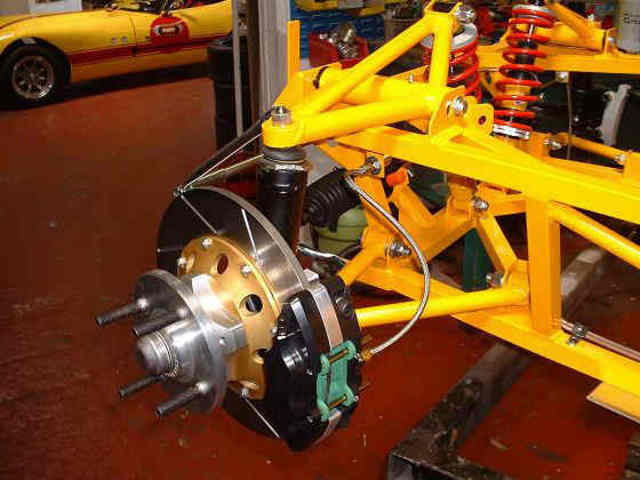
Rescued attachment in suspension.jpg
JoelP - 18/7/05 at 09:36 PM
that does look quite good
AGK7 - 18/7/05 at 11:41 PM
Hey guys,
The rocker arm type set-up was definitely something else I was looking at. I have seen a local 7 type car which uses this but on the bottom bone.
Mind you using the top bone as per pic above certainly does clean the area up quite a lot. One of the problems as I understand of the rocker arm type
is the heavy loads on both the rocker arm as well as the pivot points. Neither of these are insurmountable though and plenty have already gone
there.
This is a photo of the Alison Clubman an aussie but machine with a bottom rocker arm.

can't seem to get the image to show, it is however the only one in my alburn. (any tips on how to make this link work?? )
Thanks again.
AndrewK
Liam - 19/7/05 at 12:28 AM
Thanks for the big-up pete!
I went for rocker arm suspension - all the benefits of inboard without the hassle of working out the geometry relating to the movement of pushrods,
bellcranks etc etc.
Yes the pivot is highly loaded, but (intuitively - I haven't calculated) no more than the pivot of a bellcrank in a pushrod system. Nothing an
M12 bolt cant handle - i'd worry more about using 2 bits of 3mm steel for the bracket, which is why i doubled my pivot brackets up to 6mm (but i
have a high leverage, therefore high pivot load in my softest setting).
Bending of the wishbone is the main problem - you just have to make the top bone nice and stiff in that direction. A triangulated structure ideally,
but i've seen plenty of designs that just use beefy steel to resist bending.
The main reason I went for inboard is the scope for plenty of wheel rate adjustment. I have a selection of mounting holes for the shock on the inner
end of my rockers to play around with suspension settings easily. This is just as achievable with a pushrod design of course.
Best of luck,
Liam
rick q - 19/7/05 at 12:36 AM
The loads on the rockers are high. If you look back at the picture I posted on the previous page, the rockers were originally supported on
cantilevered studs welded to the cross frame. An additional pipe support is now added (the black frame in front of and connecting the rocker pivots)
which stiffens the whole thing up considerably.
AGK7 - 20/7/05 at 06:40 AM
One other problem with using the top rocker arm is finding a ball joint that will put up with the load.
I am using Toyota landcruiser tie rod ends as my top ball joints going into a Gemini upright, do people this this would put up with the extra load if
the shocks were transferred from the bottom to the top bone??
Landcruisers are pretty big heavy cars and being designed for off road use i can imagine that there would be heaps of load going through even if it is
steering only.
Any thoughts?
Cheers
Andrew
britishtrident - 20/7/05 at 07:00 AM
For ball joints I think Metro top ball joints have been used in the past.
But is it really worth all the complication -- I think not as the main reason for using inboard suspension on single seaters is aerodynamic. The
unsprung weight/mass arguments don't hold much water when looked at in detail, you can save much more by careful choice of rims and tyres.
The major disadvantage is the extra complication and stifness required in the front bay of the chassis and wishbones.
For a genuine reduction in unsprung mass without too many complications compound torsion bars (as per Lotus 72) are an idea --- a mid to late 80s
Honda or Rover 213 would be a suitable donor. For use on a lighter car the bar angular spring rate can be reduced by machining or better grinding down
the diameter of the centre part of the compound bar.
[Edited on 20/7/05 by britishtrident]
britishtrident - 20/7/05 at 07:06 AM
quote:
Originally posted by agk
snip
I am using Toyota landcruiser tie rod ends as my top ball joints going into a Gemini upright, do people this this would put up with the extra load if
the shocks were transferred from the bottom to the top bone??
Landcruisers are pretty big heavy cars and being designed for off road use i can imagine that there would be heaps of load going through even if it is
steering only.
Any thoughts?
Cheers
Andrew
The problem is that rod ends are self adjusting by a spring pressing against the cup the that the lower surface of the ball joint bears on. When the
ball is pressed into the socket the diaphram spring that provides the self adjustment is compressed effective negating its effect.
AGK7 - 20/7/05 at 11:55 AM
what about a spherical bearing installed horizontally?? Can these put up with the vertical loads if they are installed horizontally? I am pretty
sure i have seen this done, just seems that the inner ball would pop straight out of the outer ring? If they could then an adapter such as
http://www.raceleda.co.uk/ancilliaries.aspx
could be made up to suit? Sorry for so many question.
Cheers
Andrew
chrisf - 20/7/05 at 01:37 PM
I'm using rod ends exactly as you describe. I have a couple of designs of an inboard suspension idea in the Archived Files secion on my website
(give me a few minutes to update). Some things to consider is the packaging. I eventually got discouraged and dropped the idea. I still think it can
be done, but it is difficult. Have a look at Mathew_1 's inboard idea. His is very nice. Or Rob's BEC ZX-12.
--Chris
crbrlfrost - 20/7/05 at 07:12 PM
F1 has been known to run the pushrod directly to the upright. This can be done by running the heim joint horizontally to account for steering travel,
or vertically with a high misalignment bearing (still less steering angle however). But this get rid of the bending problems in the wishbones as well
as the stacked tolerance take up before actuation of the damper. Anyway, just something to think about. Cheers
AGK7 - 20/7/05 at 11:03 PM
Thanks for the replys guys, Chris i am having trouble finding those two guys Matthew_1 doesn't seem to have a website or archive and i
can't see any of the Robs as you suggested.
My thinking is as follows, top rocker arm similar to
these
using in Gemini uprights (similar to the Cortina units just a little lighter). For the top ball joint i will make up a spigot similar to the Raceleda
unit listed above and here
Raceleda
with spherical bearings. Taking another look at the Raceleda site they seem to offer this spigot conversion for the top and bottom of the cortina
units
top and bottom spherical bearings
I presume then that in this application the bottom joint would be taking the load from the traditional outbound shocks and as such can put up with the
load (as you also suggest Chris).
One of the advantages i see in going this way is that i could then simply remove the Gemini uprights and insert some nice and light Rorty style
uprights by simply turning the spherical bearings from horizontal to vertical.
Rorty's
I realise that many don't see the value in the trouble but with a rocker arm you remove the problems of push rods and rockers etc and it
definitely "cleans" up the look of the car.
Thanks again for all comments.
Sorry again for the long winded post.
Cheers
Andrew
bimbleuk - 21/7/05 at 08:46 AM
If you want a good example of inboard suspension look at any Striker. If I remember correctly it was originally design with inboard suspension so that
over 15 years! Also Strikers dont use anti-roll bars.
[Edited on 21/7/05 by bimbleuk]
ned - 21/7/05 at 09:14 AM
another slightly different way to do it is like the quantum extreme:
http://locost7.info/files/suspension/QuantumExtremeFrontSus.jpg
this may reduce the weight of and simplify the mechanism a little, but you need ot make sure your shocks work correctly on the horizontal.
Ned.
[Edited on 21/7/05 by ned]
geoff shep - 21/7/05 at 10:25 AM
I think Rorty's design is outboard - there's a thin piece of wire where the coilover would go.
My Robin Hood has inboard suspension - but I don't think it's that highly tuned to worry about how much unsprung weight I've got!
AGK7 - 21/7/05 at 11:07 AM
Thanks for the comments guys, talking to a few guys locally i am pretty sure the Landcruiser tie rod end will stand up to the job. Now to start
modelling it up and see how it goes
Quantum certainly looks like a nice car!!
Geoff Rorty's certainly are outboard i was only refering to the upright, with spherical bearings it would be a very easy change over for Gemini
to fabricated uprights.
Thanks again for all the input.
Andrew
Liam - 21/7/05 at 02:38 PM
I'm using maxi balljoints as my top joints, and i've seen lots of other inboard rocker arm designs that use production car ball joints too -
sylva, fisher etc etc. So i dont think you'll have a problem as long as your joint is up to it.
Without chopping one apart I can't be sure, but there certainly doesn't seem to be any springing inside my maxi joints as BT mentions.
There's certainly no movement at all when the joint is used in compression - just seems to be a big solid ball joint which I'm sure will
work fine.
One thing to be aware of - locosters commonly use Transit drag link ends for top ball joints, and these joints have only just enough movement for the
suspension travel. They top wishbones therefore have to be made with the joint pointing upwards slightly to prevent it from reaching the limit of
travel in droop. Looking at a picture of MK top front wishbones will explain this much better than my words - just make sure your ball joint will not
go solid in any part of your suspension travel!
liam
britishtrident - 21/7/05 at 03:01 PM
I seem to recall the Maxi the (top) ball joint was designed to take spring/hydroelastic displacer loads pressing the top whishbone down into ball
joint socket,but it is more than 20 years since I last changed a Maxi/Allgero ball joint.
Using a tre or drag link is a different matter.
britishtrident - 21/7/05 at 03:04 PM
ball joint info here http://www.ltsa.govt.nz/publications/infosheets/infosheet-2-05-200310.html
davidfe - 31/12/05 at 05:16 PM
I think the most interesting thing about Liam's build is I think it is AWD.
David Edwards
quote:
Originally posted by scoobyis2cool
Hi Andrew, welcome to the site. Sounds like an interesting idea, I don't see any reason it couldn't be made to work in a 7 and as you say it
has a number of benefits over the traditional outboard design. (Having said that, outboard suspension is used on some of the best handling cars
around, such as the Lotus Elise, so it's not something to disregard completely!).
I was looking through Liam's photo archive yesterday - HERE.
He's made a nice looking inboard set up, maybe you could get in touch with him for some pointers. I'm sure other people have done it too but
I don't know who they are!
Good luck with the build, I look forward to seeing how it turns out.
Pete
WIMMERA - 31/12/05 at 11:05 PM
Smith warns against adjusting ride height by altering push rod lengths in Engineer to Win (page 221)
Wimmera
Mark Allanson - 31/12/05 at 11:12 PM
..and it says 'INDIA' on bus tyres , but I have never heard of one that went that far.
WIMMERA - 1/1/06 at 01:09 AM
His exact words " not to be fooled around with by the uninitiated, imprecise or unwary" =a rather nice turn of phrase I thought
Wimmera
Syd Bridge - 1/1/06 at 12:02 PM
quote:
Originally posted by WIMMERA
Smith warns against adjusting ride height by altering push rod lengths in Engineer to Win (page 221)
Wimmera
Altering pushrod length is little different to altering spring seat position up and down. Does the same thing.
Why do you think that most racecars with front pushrods are configured to be adjustable? Just for looks?
EDIT... Further, it is desirable to keep the angular geometry between the pushrod/rocker/coilover fairly even, within limits. A little variation
won't cause any real upset, particularly in a road car. If you are adjusting ride height by large amounts, then both pushrod AND coilover will
need to be altered. At least, that's how the racers do it.
A lot of those old books need to have a 'Useful Working Life' date, or 'Use BY...'
Suspension is no 'Black Art', just adjustment and feel. Heck, what is a perfect setup for one driver, is undrivable to another. So...?
Cheers, and Happy New year All, you too Rorty(alias Wimmera)
Syd.
[Edited on 1/1/06 by Syd Bridge]
Ian Pearson - 1/1/06 at 06:25 PM
Syd, I'm a complete computer numpty, how on earth are you able to find out if someone is posting under another name?
[Edited on 1/1/06 by Ian Pearson]
JoelP - 1/1/06 at 08:04 PM
you could always hack them, failing that, its guesswork. 
