
Started to fuel inject my crossflow - speeduino
MikeR - 26/4/20 at 08:26 AM
So being typically me and having the opportunity to finish the car (or get a lot closer) during this lockdown i've decided that i really need
fuel injection.
The intention is to use a speeduino (so keeping with the locost home built theme) and work in stages. Stage 1 is get ignition working and then once
happy with that get injection working. Hopefully this means everything builds on itself and nothing is wasted / redone. I've also got another way
to delay myself with the injection - using DCOEs for the butterfly and making a manifold with the injectors fitted underneeth. Hopefully this will
retain the old school looks. If that doesn't work i've got some blackbird throttle bodies (42mm!) i bought 12ish years ago.
Cost wise i'm also hoping to keep with the locost ethic. So far i've bought from DIY-EFI a build speeduino (i did solder one together but it
let out the magic smoke when testing - i figured buying one was sensible). I had james modify it to use the ULM chiip in the prototype so i can drive
a few extra things.
Looking at the trigger wheel i dug out a couple i'd bought (many) years ago and looked at what others had done. It seems many people just bolt
the trigger wheel to the crank pulley with a few washers acting as a spacer. The idea being the clamping force holds it tight. Its the same approach
the webber setup uses. I wasn't totally happy with this. Id also then have to make a bracket to hold the VR sensor .... so i bit the bullet and
bought the excellent QED setup. QED were fab and the bits turned up two days later. (did i mention keeping the costs down - oh well)
Fitting the QED VR bracket and wheel was a doddle. Both look excellent. I then found the standard ford VR sensor was about 4mm from the wheel. Not the
1mm it needs to be. Much pondering and i realised the spacer brackets supplied with the bracket mean it can fit a standard pulley, with them removed
it fits the QED smaller pulley. VR sensor from ebay (for a tenner - hopefully it works).
Now the problem - the QED pulley doesn't have a notch for TDC ..... only noticed this once everything was bolted up and the engine in place. I
don't have a dial gauge and dont intend taking the head off..........
bugger.....
So length of 8mm copper tube in plug 1 with a mark around the level of the plug. Bit of wire zip tied to the VR sensor pointing to a protractor
i'd printed (web site - https://www.blocklayer.com/protractor-printeng.aspx) and stuck to the crank pulley with wood glue, long lever on the
crank pulley bolt on a saturday night and lots of foward, backward .... did it move? mark it.
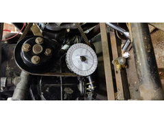
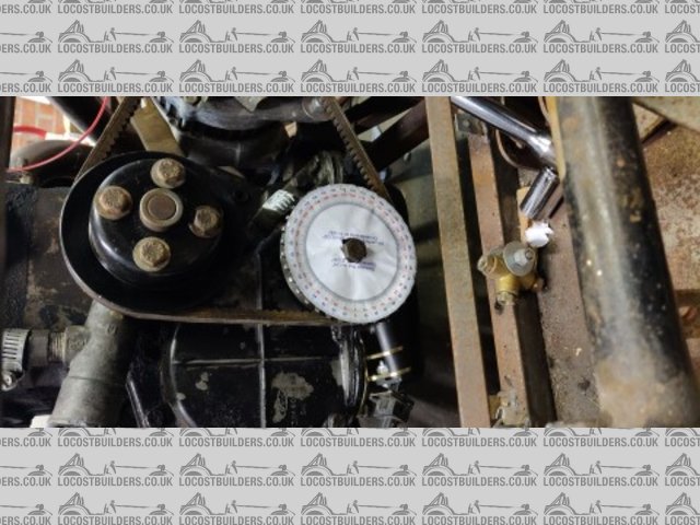
trigger wheel setup
tdc setup
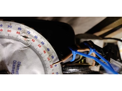
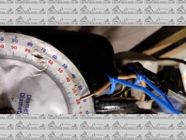
Marked when it stopped moving up and then when it started moving down. Halfway between the two is my guess at TDC. I've thencut a very small
notch in the pulley over the standard TDC mark. Its not perfect but hopefully close enough to get me a basic running engine.
Picture of the Speeduino to follow when i get a moment to write the next update on wiring it in (temporarily).
Intent is to fire the engine up on dizzy and check it runs ok (its been 15 years since i last used it). Then turn spark over to speeduino via a VW
coil.
If anyone has a decent source of VW coil HT lead connectors i'd love to know. They're the M4 type also used in later ford mondeo / focus
coils.
MikeR - 26/4/20 at 08:28 AM
If anyone has any maps for a crossflow (megajolt / megasquirt or something else) i'd love to have a look. Engne is currently a standard 1600 with
GT valves.
(i'm still trying to get my head around creating a basic map to fire it up - one thought was to monitor the spark from the dizzy and see if could
reuse that. Intent is to do MAP based whilst i've got the old weber downdraft fitted.)
wonderfulweasel - 26/4/20 at 10:18 AM
Nice work Mike!
I'm doing very similar but with megasquirt, starting with ignition and bike carbs, then I'll progress to a set of bike bodies. (All from
bits I have leftover from a few years ago, so hopefully keeping costs down). I'll be interested to follow this thread.
I have a couple of crossflow ignition maps from megajolt from years ago (sure I can find them!). They're for a 1300, with fast road cam, etc, and
TPS rather than MAP, but should give you somewhere to start. U2u you're email and I can share with you.
MikeR - 26/4/20 at 10:53 AM
I've got a couple of 1700 maps from the megajolt forum but not 1300. I'll u2u my address. It would be interesting to compare.
Now I've started this thread I'll hopefully remember to take pictures as I go for anyone else day enough to try this (so hopefully they
won't have to do everything 3 times like me)
rusty nuts - 26/4/20 at 11:01 AM
Converted mine probably ten years ago, first thing was to make a spacer to fit inside the steel crankshaft pulley( no point using the original pressed
steel item) to allow the trigger wheel( trigger wheels.com?) then make the bracket for the sensor. Set to TDC (already established when rebuilding the
engine) then position the trigger wheel so the missing tooth was 90deg BTDC , the trigger wheel was pre drilled with a 5mm hole that would be covered
by the crank pulley washer, when happy with the positioning the crank pulley was partially drilled through using the pre drilled trigger wheel as a
guide then a 5mm roll pin knocked in and cut off flush before fitting and tightening the pulley bolt and washer. If I ever have to remove the pulley
at least the TW is in the correct position . HTH
The distributor was removed and a plug turn to block the hole, it could be used as a breather I suppose.
The inlet I made to fit a set of bike TBs , but if I were to do another I would modify the throttle quadrant to give a more progressive throttle
action , also don�t expect the manifold rubbers to hold the TBs , they will likely fall off, I braced them using 3 pieces of mild steel to held them
on.
I had a base map from Emerald but found a sniff of brake cleaner down the TBs got it started enough to start tuning , Dave Walker advises don�t
spend too much time trying to set up cold starting as everything warms up quickly.
I probably have a map somewhere for my engine which has a Kent BCF2 cam , big wave head and a set of 36mm Kawasaki TBs but it may be no good for
your ECU?
If I can help let me know
paulf - 26/4/20 at 11:03 PM
Good to see your making progress again Mike,as you may remember i used to have a 1600 gt crossflow in my car on megasquirt and may have some maps on
an old computer if i can get it to boot up i will have a look in the next few days.
Paul
MikeR - 26/4/20 at 11:13 PM
I do remember your car Paul - all help gratefully received
MikeR - 5/5/20 at 01:42 PM
Small update..........
Bought lots of bits

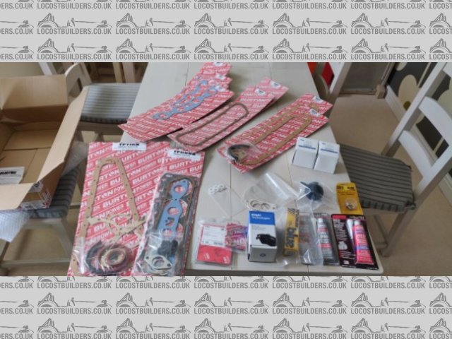
burton parts
gaskets, oil filters etc from Burton (i think i took support local business too far)
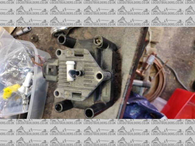
vw coil
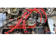
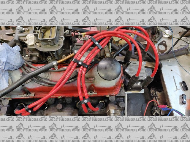
Also bought bits to make up my plug leads from Mr-Retro-Leads-Plugs from ebay. Contacted the seller first to ensure i got the right bits. Having got
them delivered i panicked the coil plug was wrong. 24 hours later i double checked and it is right. (yes the tower is broken on the second hand coil.
I've got the bit to glue in and i have a new one as well).
Coil part is "M4 COIL BOOT TERMINAL FOR GOLF ZETEC NEW IGNITION HT 8MM OR 7MM KIT COIL PACK"

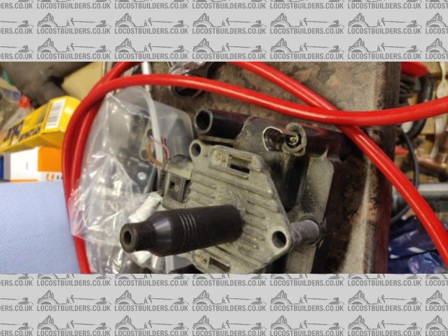
HT parts
I now need to make the coil bracket before making up the leads. The thinking is to mount it from the top bellhousing bolts.
I also did a lot of hunting for some water and air temperature sensors. Figured i should be able to find something cheaper than 15 pound a sensor.
Found a couple for around 8 pounds (the middle one is the water temperature sensor i'm replacing).

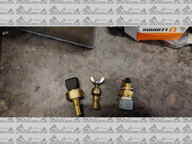
sensors
I'm using,
Air - PEUGEOT 605 6B Air Intake Temperature Sensor 2.0 3.0 2.1D 2.5D 89 to 99 Sender
Water - TRANSIT CONNECT MONDEO ESCORT FOCUS TEMPERATURE SENDER SWITCH 91AB-10884-AA
So I figured as i still had the clockwork bits on the engine I should start it. That way i know it runs and any problems are due to the electronic
ignition (speeduino). Well first I changed the 15+ year old oil with some never opened but equally old 20/50 smart price oil. Turned the engine over
on the starter with no plugs and didn't get any oil pressure ............. how did i do that on a car with no instruments / dash etc ....... well
i made one from pallet wood, random switches and gagues from my dad (so from the 1960s).

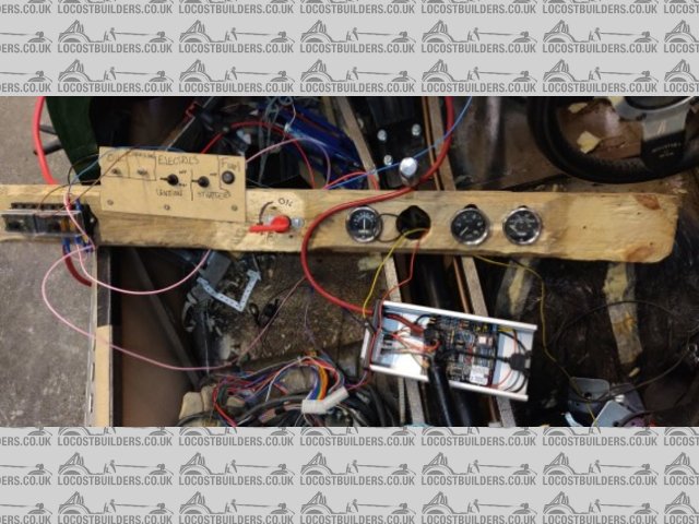
dash2
Done a few things (like pack the oil pump with grease) and still no pressure. Now debating if i replace the pump with a spare or just try and start
it.
As i was looking at starting i realised the fuel pump didn't seem to be sucking fuel from my swirl pot (temporarily converted to being a fuel
tank with the addition of a blanking plug for one outlet and adding a copper tube to the bottom of one connector so it can suck from the bottom of the
tank, finally replacing the 044 pump with a fuel filler).

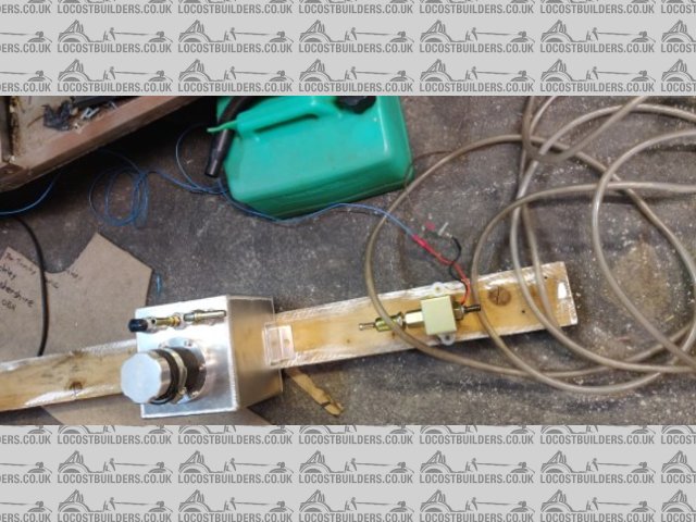
fuel system
So fitted an electric pump, added a fuse and a switch to the pallet wood dash and that runs when the ignition switch is active.
Now do i try to start it OR run on the starter without plugs to get pressure???????
ps still worrying i have got TDC wrong so thinking of making up something with lego to amplify the piston movement to help prove my marks are right.
rusty nuts - 5/5/20 at 05:52 PM
When I converted mine I found the easiest place to fit the coolant temperature sensor was in the heater hose , I made the inlet manifold with a heater
outlet which takes coolant from the hottest part of the engine and turned up a handy lump of ally to fit the hose and take the CTS.
See your other post for an easy to make and use tool for finding TDC
[Edited on 5/5/20 by rusty nuts]
MikeR - 10/5/20 at 11:25 AM
So a little progress.
As Rusty metioned I had a panic my TDC marking wasn't correct. Not having a dial gauge i improvised with some lego and was very impressed that it
worked first time and so well.

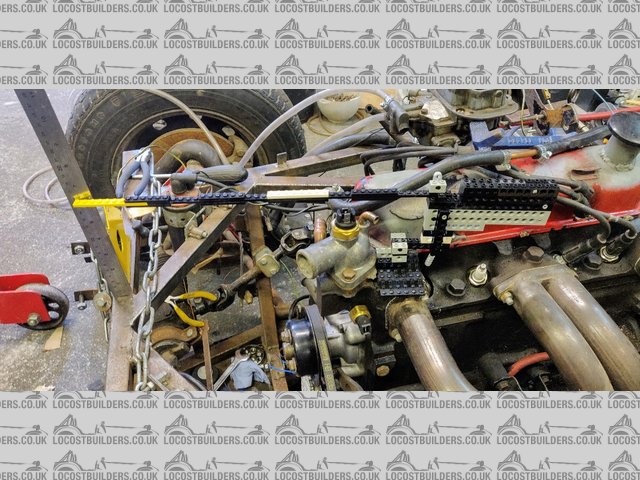
Lego dial
Turns out i had TDC spot on.
Lets skip accidentally putting diff oil in the gearbox (the package is almost identical). Vaccum pumped the box and put the correct stuff in.
So I tried and tried to start the engine on points to check everything was fine. I'd then have a known working engine to work from. Many an
evening checking and double checking the timing and just couldn't get it to start. Eventually after much cider (over many nights), late evenings,
pondering and generally being grumpy that a 40 year old engine on 10+ year old points wouldn't start ....... my wife sent me a text from the
lounge "i heard that" ......... it started. I may need to repack the silencer 
Obviously started it a few times to be sure it would keep working 
So in excitement I connected up the speeduino, hacked off the 9th trigger wheel before TDC, connected up the map sensor and turned it all on with the
aim to log a start up proving it was working.
BANG
smoke
[swear words]
turns out i forgot i'd had the brain way to make both connectors to the speeduino oppoosite way up to each other so easier to attach. I did this
after i'd made the power cable........ so I put 12v to ground.

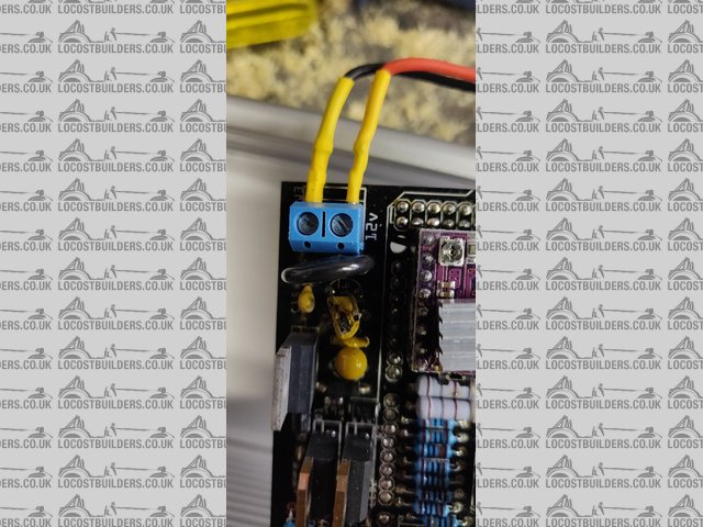
speedy bang
(you're looking at the yellow bit in the middle thats now got a hole in it)
So disaster and being back to grumpy sod. I decided to connect to the speeduino via USB and see what happened. It respnded. Fired up the engine and
its providing readings for RPM and map. Speaking with Josh the designer of Speeduino and he thinks replace the Capacitors on the power circuit and
i'll be fine. The latest revision (4.4b) has better protections.
So progress. Going to make up some temporary spark plug leads and then wire up the VW spark module to speeduino (hopefully not blowing anything up in
the process).
ttalps2000 - 11/5/20 at 07:43 AM
Hi Mike
I have just completed my Speeduino build and install.
If you need any help or guidance then let me know. Had a few issues along the way, but most have been the install rather than the ECU
MikeR - 11/5/20 at 01:20 PM
Fab. What's your engine setup?
I do like speeduino. I could just do with not making silly mistakes. I think the biggest problem is the lack of a decent connector for the wiring to
the outside world. I now see it fragmenting with a number of people producing boards.
MikeR - 20/5/20 at 09:35 PM
So some progress..... with a few false starts and mistakes.
So since the last update I've repaired the board. Powered it up via USB and everything seemed fine. Powered with 12v and .... the IDLE addon
board DRV8266 started to glow. Quickly powered everything off and threw it away (replacement ordered via Amazon). General view is the 12v via ground
will have killed the board but everything else should be fine.
Wired in the VW coil (OEM 032 905 106 B ).
Pin 1 � trigger 1 (cylinders 1&4) from ECU (which i'll put against ignition 1 / pin 7 on the speeduino ECU)
Pin 2 � 12v ignition power
Pin 3 � trigger 2 (cylinders 2&3) from ECU (which i'll put against ignition 2 / pin 3something on the speeduino ECU)
Pin 4 � ground
Set speeduino to crank at 10 degrees advance and locked ignition (for testing) at 10 degrees.
Set dwell time at cranking at 5ms. Normal running 3ms. 1ms trigger. Overload protection set to 8ms max.
Trigger on signal going low.
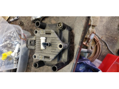
Its also important to ground the coil via the bolt holes, ideally grounded onto the block not the chassis. I made my own bracket to mount the coil off
the bellhousing bolts. I cheated and used a standard B&Q 90 degree mending bracket. I couldn't in the lockdown get one wide enough so welded
some steel on the side of the one i had. To aid the grounding I welded some nuts onto the bracket. At some point I'll paint it. To stop it moving
sideways (it is top heavy with the coil) i added a sideways stay which also doubles for the engine earth point where it bolts to the bellhousing.
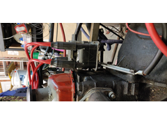
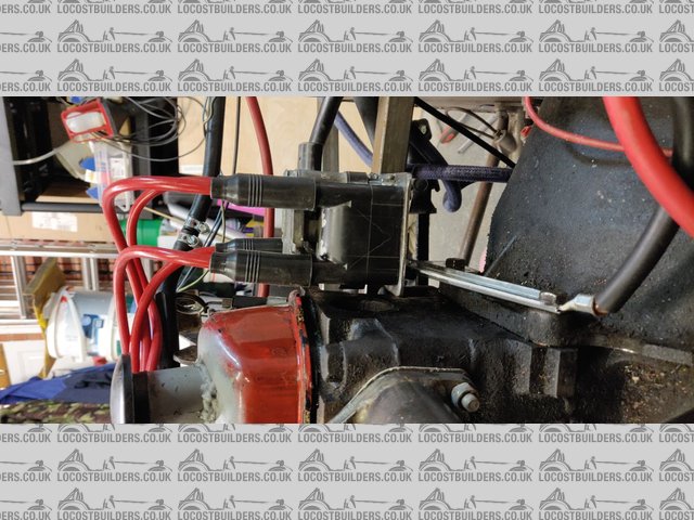
coil mount
I also had a go at calibrating my water temperature sensor. Not sure what I'm doing wrong but the doesn't seem to work. I set up a rig where
I could monitor the temperature in a pan of water with a raspberry pi and every 5 degrees i measured the resistance of the sensor via a multimeter. In
theory i thought this would give me the values needed to calibrate the sensor in tunerstudio. Entered the 3 values out of my collection of 20 and
tunerstudio gives strange temperatures.

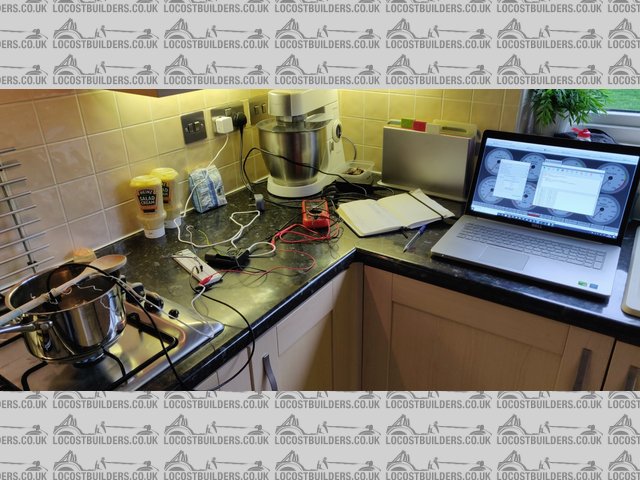
temp measuring
Wondering if I make an arduino curcuit that matches what the speeduino has and then repeat the process.
Ignoring the temperature i made up my ignition leads. Plug ends were easy. The m4 terminal end was a challenge. It contains a plastic bit that narrows
and i couldn't use the 8mm leads, they just didn't fit. Trimmed off the red lead cover and they just fitted. Completed the cables and fitted
them to the engine.
plug leads
So crossed fingers and had a go at starting ............ engine span and with lights fitted to the HT leads (great little gadget that attaches to the
plugs and the spark lead attaches to it. When the spark passes a little light glows) ............. nothing.
I checked everything, lifted a plug and rested it on the block - nothing. repurposed a traditional copper lead making the normal distributor end fit a
m4 pin and .......... nothing. checked continuity on the wiring - works perfectly. Round and round in circles. Eventually posted for help on the
speeduino facebook site. Everything suggested i'd checked but i checked again ......... then i noticed. Cable to speeduino connector wired to
pins 1 and 2. Inside the case it was wired to pins 3 and 4. It was also suggested that i change jumper 1 to 12v instead of 5v and put a 1k ohm
resistor on each trigger wire.
Made the changes and ........................... (have a guess) ............................. It started.
Runs terribly and stalls if you try to accelerate. If you leave it then it stalls after a few seconds. Need to now check the timing to see how close
it is to 10 degrees BTDC and adjust the triggerwheel offset. Its also likely the carb which has stood for over 10 years is a bit gunky.
Next steps are to sort out the timing and get it starting on the button then worry about the map and tidying up the very temporary
'dashboard'.
[Edited on 20/5/20 by MikeR]
ttalps2000 - 21/5/20 at 07:15 AM
Glad to see your getting there with it now. Are you running the original dizzy for your pickup or gone with a 36-1 wheel?
My VW coil is set at 5v for the trigger, which is the correct voltage for them and works fine. Some people have said that the 5v output from the board
can be lower sometimes and cause issues.
Mine is on a Zetec with ITBS. Currently runs very rich and having issues getting it to run leaner, but still drivable and be able to start it.
Injectors have gone for cleaning and flow testing as they have been sat for 5+ years so i expect they are not flowing as they should.
Temp sensor wise, i did my own calibration with no issues. Did 3 tests and took an average. Have you put in the total resistance, which is usually
2980 or something like that. Look on the calibration in TS for the Bosch ones and copy the total valve on the top right hand field and ensure you have
this entered too.
MikeR - 21/5/20 at 04:06 PM
I've gone with a QED trigger 36-1 trigger wheel. Long term plan is fuel injection, just want to get spark sorted with the carb first. Its now
running on 5v trigger to the VW coil. It starts and runs for a few seconds. I'm suspecting the problem is a 15 years since used carb, but in the
time i can get it running i'm confirming i've got the trigger wheel missing tooth offset correct (looks like i'm about 5 degrees
out).
Love to know more about how you set the temperature sensor up.
I had a DB18s2 something sensor rigged up to the raspberry pi outputing the temperate to silly decimal places every second. Every 5 degrees i
measured the resistance on my multimeter and recorded the values. I took the values for 2 degrees (the lowest i could get with iced water) 65 degrees
and 98 degrees (the highest i could get with boiling water) and entered them into tunerstudio. The numbers seem very low compared to others.
2 = 2335 ohm
65 = 237 ohm
98 = 75 ohm
I've also taken a reading at ambient air temperature and tried that instead of 65 thinking it should then display a temperature close to ambient
and got a stupid number instead.
Now wondering if i need to make the curcuit used in the speeduino and get a spare arduino to record the values so i can create a data file.
(after my preivous wiring mistake, i'm half expecting i've done something silly with wiring)
ttalps2000 - 22/5/20 at 09:30 AM
To setup the trigger point, make a mark on the crank wheel where TDC is, lock the timing in TS to zero degrees and then adjust until the mark is at
you TDC position using a timing light. Do this with the plugs removed and the fuel turned off if pos. Then you know you are at TDC and firing in the
correct place. You will be surprised how far out it most likely is. 5 degress out will make a huge difference!
Temp sensor wise - i used a multimeter connected to the sensor and a saucepan on a hob with a thermometer. The first test i did was different to the
others, so i assume the sensor was still heating up.
I did 25, 85, 100 degress. Did 2 further tests and both were identical and so went with those figures. Dont need masses of points etc. Worked fine for
me anyway. just ensure the total resistance is set correctly, otherwise it has nothing to scale from.
MikeR - 9/6/20 at 10:15 AM
So very little progress - home schooling combined with family stuff has limited time in the garage. I've then managed to get some sill reoccuring
headache for the last 10 days. Doctor isn't worried my head is going to explode so i've decided to try and focus on something positive .....
at which point i've knackered my achillies. As i've got to keep my foot elevated I thought its an ideal time to work out how to add WIFI to
the speeduino.
I could do bluetooth but thats easy and as you're hopefully learning i don't tend to pick easy.
Aim is to program an ESP201 to provide the wifi interface. I've picked this over an ESP01 as its got a better ariel than an esp01. Currently
struggling as with flashing but i'm sure i'll figure it out and then solder the wires direct to the arudino board.
By the end of this i'll hopefully have the only wifi enable crossflow in the world
Once my ankle is better i'll have another go at programming the coolant temperature sensor.


