
A question for the mech eng's
02GF74 - 18/6/17 at 07:35 AM
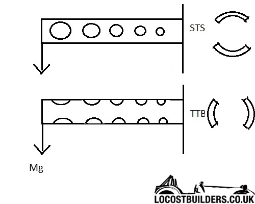
Let's say I have a tube that is fixed at one end and a force is applied in one direction at the other, as per CAD drawing below. Not sure it
matters but the tube is carbon fibre, 22 mm OD with 1 mm wall thickness, about 300 mm long.
The greatest stress will be at the fixed end due to moment so it needs to be strongest there, wherease the opposite is true for the free end. To
optimise the weight of the tube, either the wall thickness can be varied, which is not easily done, otherwise material can be removed; one way is to
drill holes of decreasing size as in the drawing (or same size but fruther apart).
The question is which was will result in a stronger tube - drilling holes side to side (STS) or top to bottom (TTB)?
Taking the drilling it to the extreme so removing the opposing quarters of the tube (the 2 diagrams on the far right), I would say TTB will resist
bending better - but is that correct?
DW100 - 18/6/17 at 08:58 AM
Side to side will be strongest, the top will be in tension and the bottom will be in compression. The centre will be the neutral axis.
If you look at structural steel beams they sometimes have holes in the side to lighten them.
liam.mccaffrey - 18/6/17 at 09:18 AM
wot he said ^
Sam_68 - 18/6/17 at 09:28 AM
Thirded
...but does it have to be a tube. The most efficient for for the loading you've illustrated would be an I-beam
02GF74 - 18/6/17 at 10:29 AM
Ok, so where is my "side cut away" analogy going wrong?
Sam_68 - 18/6/17 at 12:07 PM
As DW100 has already explained very clearly, but to expand upon what he's said:
If a beam bends the top and bottom form arcs. If you imagine extending those arcs until they form complete circles, you'd find that the arc that
follows the curve of the top of the beam has a smaller radius (hence smaller circumference) than the arc that follows the bottom of the beam.
It therefore follows that the beam (which is just a segment of those circles) is getting shorter on top, and longer on the bottom. As DW100 has said:
the material at the top is being squeezed (compressed); the material at the bottom is being stretched (placed in tension).
The material in the middle is what we call the 'neutral axis', because (assuming the material top and bottom is resisting
tension/compression to an equal degree), it is neither being compressed or stretched: it is, in fact, doing no work at all.
The further from the neutral axis that you place material, the more work it is being made to do, so for maximum efficiency, you need to make your beam
as deep as possible (placing the top and bottom as far as possible from the neutral axis); then put as much material as you can out at the
extremities, where it's working hard, and as little as possible close to the neutral axis, where it's doing very little.
This is the principle behind I-beams, lattice girders and the rest.
Your STS diagram approximates to a lattice girder: you've removed material from the neutral axis, where it's just dead weight and isn't
doing any work.
On your TTB diagram, you've removed material from the areas where it's doing most work (under most stress), so it will substantially weaken
the member.
Angel Acevedo - 18/6/17 at 12:23 PM
quote:
Originally posted by 02GF74
Let's say I have a tube that is fixed at one end and a force is applied in one direction at the other, as per CAD drawing below. Not sure it
matters but the tube is carbon fibre, 22 mm OD with 1 mm wall thickness, about 300 mm long.
The greatest stress will be at the fixed end due to moment so it needs to be strongest there, wherease the opposite is true for the free end. To
optimise the weight of the tube, either the wall thickness can be varied, which is not easily done, otherwise material can be removed; one way is to
drill holes of decreasing size as in the drawing (or same size but fruther apart).
The question is which was will result in a stronger tube - drilling holes side to side (STS) or top to bottom (TTB)?
Taking the drilling it to the extreme so removing the opposing quarters of the tube (the 2 diagrams on the far right), I would say TTB will resist
bending better - but is that correct?
Not trying to be a prick but....
I have some questions and comments...
- What are you trying to accomplish?
- Stronger tube?
- Lighter tube?
- Bendy tube?
- Stronger tube will be tube with NO HOLES.
- Holes will make tube lighter and weaker.
- Bendier (is this a word?) tube would be holes top to bottom.
- Stiffer tube would be Side to Side (The last two provided load is Top to Bottom)
If load will be applied to end of tube, apprpriate reinforcement may be needed.
HTH
Sam_68 - 18/6/17 at 12:51 PM
quote:
Originally posted by Angel Acevedo
What are you trying to accomplish?
quote:
the OP said
To optimise the weight of the tube
In other words (as I read it): strength to weight.
It would be useful to know the application.
Another point that we haven't touched on yet is that by drilling a circular section tube, you're effectively creating a beam with
pre-buckled webs, which will be very weak indeed.
As the old Irish proverb goes: "If I were you, Sir, I wouldn't be starting from here"
Angel Acevedo - 18/6/17 at 01:10 PM
quote:
Originally posted by Sam_68
quote:
Originally posted by Angel Acevedo
What are you trying to accomplish?
quote:
the OP said
To optimise the weight of the tube
In other words (as I read it): strength to weight...
It would be useful to know the application.
Another point that we haven't touched on yet is that by drilling a circular section tube, you're effectively creating a beam with
pre-buckled webs, which will be very weak indeed.
As the old Irish proverb goes: "If I were you, Sir, I wouldn't be starting from here"
JJJ...
You�re right, my question would be better asked What do you want to do with the tube? as he is starting with Carbon Fiber which is inherently high in
strength to weight ratio...
Maybe better to start with variable thickness as fishing rods are made.
Sam_68 - 18/6/17 at 01:17 PM
Regardless of the material, a tube is the wrong shape for a cantilever beam, if you know the direction of loading. Even in carbon fibre, a pultruded
or sectional I-beam would be more efficient; failing that a simple box section.
And you absolutely shouldn't ever drill a tube for lightness if it's going to take bending loads, for the reason previously given:
it will buckle at the 'webs' between the drillings at a very low level of loading.
[Edited on 18/6/17 by Sam_68]
britishtrident - 19/6/17 at 10:49 AM
What everybody has already said, for a beam in bending choose an I -beam or if there forces from other directions a box section.
A carbon, kevlar or glass fibre tube needs specialist design expertise with regarding fibre orientation and the lay-up of the layers.
Mr Whippy - 19/6/17 at 11:24 AM
I hope this is not related to a wing spar
b14wrc - 19/6/17 at 11:26 AM
And as for drilling holes into a fibre reinforced tube, discontinuity will be had in the fibre architecture, ie breaks. Not great for structural
integrity. Fatigue will likely result from micro cracking at the holes.
I would be tempted not to weight save on that type of structure - being carbon fibre.
Also, the weight saving on that tube geometry is going to be minimal anyway.
Rob
MikeRJ - 19/6/17 at 02:35 PM
quote:
Originally posted by Mr Whippy
I hope this is not related to a wing spar
 I hope not!
bozla - 19/6/17 at 06:42 PM
Great to see loads of good information.
Just to add additionally (thanks Sam) about shapes:
Shapes have a huge impact on how capable a part can take force.
Take a look here:
www.materials.ox.ac.uk/uploads/file/design/design_notes3.ppt
For example, a larger diameter tube will be stiffer but will buckle at a lower force. It's really complicated by adding drilled holes as you
create stress concentrations thoughout - it'll be better to get experimental results. Also, the quality of cut and size of hole will massively
affect the result.
Another factors that a lot of engineers forget is fatigue resistance. Mild steel (that we normally build kit car frames out of) is extremely
resilient in fatigue resistance, but if you change material it becomes a consideration.
To answer the OPs questions:
The question is which was will result in a stronger tube - drilling holes side to side (STS) or top to bottom (TTB)?
>STS
Taking the drilling it to the extreme so removing the opposing quarters of the tube (the 2 diagrams on the far right), I would say TTB will resist
bending better - but is that correct?
>STS
[Edited on 19/6/17 by bozla]
nick205 - 20/6/17 at 07:59 AM
Knowing/understanding the application would definitely be a start point. With more background understanding I'm sure people could (if required)
comment/advise in more depth.
As has been mentioned above drilling holes seems a bad idea to me. I've seen people do that to bicycle seat posts in an effort to reduce the
weight by a few grams. The result tends to be a weaker component for very minimal weight reduction.
How desperate are you to save weight from what will already be a light component?
I could understand the weight desire for RC aircraft or perhaps car applications. In terms of a 7 type car there are surely easier places to make
more meaningful weight savings.
An Aluminium "I" beam could provide the strength you're looking for, but I doubt it would lower the component weight. Aluminium could
of course be easier to fix things to as well.
Mr Whippy - 20/6/17 at 11:39 AM
imo if you can loose more weight going to the toilet it's not worth bothering with...
02GF74 - 20/6/17 at 05:21 PM
quote:
Originally posted by Mr Whippy
imo if you can loose more weight going to the toilet it's not worth bothering with...
sadly I've have not yet managed to successfully train my anus to poo on demand so that is not really an option.
02GF74 - 25/6/17 at 08:12 PM
To conclude this. The tube is to add a bit of strength to a lightweight carbon fibre seatpost. the seatpost is used within spec. and probably is
designed to flex a bit but since it is in a full suspension frame I don't need that so wanted to stiffen it a bit.
In the end I did not bother drilling for there reasons:
- as reasons above
- weight saving would be minimal (I calculated a 14mm hole would be 0.1 g)
- risk of damage to the lay up (as an pre-cursor I did drill two holes near the base of the original seat post (common practise on alloy posts) and
there was some fraying on the inside.
Post weight before 177g, after 208 g with a 275mm tube inside. Will see what difference it makes.
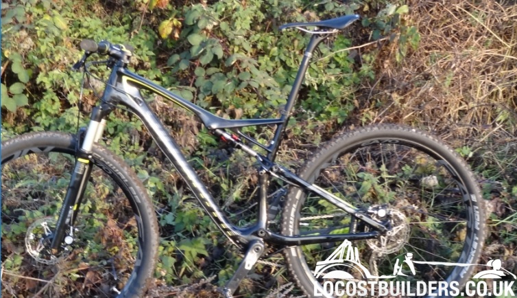
Mr Whippy - 5/7/17 at 06:06 AM
hmm if you'd shown the picture of your bike in the first place I'd say don't weaken anything with holes, it looks highly stressed as it
is. If anything I think I'd have fitted a solid plug (carbon or hardwood) in the seat post at the point where it exits the frame to help prevent
it snapping there, the bending moment at the point must be tremendous even if it's carbon.
02GF74 - 5/7/17 at 06:31 PM
I deliberately didnt say what the application was to avoid comments like "have a haircut", or "blow your nose" or ye olde classic
"take a dump", none of which help in answering the question therefore im not interested in reading them. 
Trying to save a few grammes with bikes seems to attract derision yet when someone asks about a lighter battery, wheels, exhausts etc. Those sort of
comments arent posted. None of that is neither here nor there, if i want to save a few g ill do it and think i know enough about stuff to do it
safely, so far there have been no failures.
The post is used within its limit both in terms of rider weight - just - and minimum insertion. It is designed to flex acting as a simple shock
absorber, but since bike has rear suspension, i didnt want that.
steve m - 5/7/17 at 06:59 PM
Ride the bike naked, should save a few grammes
or fill the tyres with nitrogen
Schrodinger - 5/7/17 at 09:03 PM
quote:
Originally posted by 02GF74
I deliberately didnt say what the application was to avoid comments like "have a haircut", or "blow your nose" or ye olde classic
"take a dump", none of which help in answering the question therefore im not interested in reading them.
Trying to save a few grammes with bikes seems to attract derision yet when someone asks about a lighter battery, wheels, exhausts etc. Those sort of
comments arent posted. None of that is neither here nor there, if i want to save a few g ill do it and think i know enough about stuff to do it
safely, so far there have been no failures.
The post is used within its limit both in terms of rider weight - just - and minimum insertion. It is designed to flex acting as a simple shock
absorber, but since bike has rear suspension, i didnt want that.
My first thoughts were ride without socks would save more but have realised you were not just drilling the seat post but drilling an additional tube
to insert inside the seat post to add stiffness. If I have understood this correctly the how did the additional tube work? What sort of riding do you
use it for?
02GF74 - 6/7/17 at 12:40 AM
Riding described as xc, i hardly ever leave the ground.
Stiffened post feels vastly better at a cost of 30g but unsure if inner tube will stay put as it was a very hot day when i mixed the resin (possibly
too much catalyst?) and smeared on inside of post, went off in anout 5 mins, so im expecting it not to hold the inner tube well resulting in creaking.
MikeR - 6/7/17 at 11:29 AM
folks - thanks for this thread. Its been a bloody good read during my lunch and reminded me just how helpful and knowledgeable this forum is.
Its also pointed out my instinct was wrong and i now understand why.