
Rover v8 switching to bike TBs cooling setup
Chris_Xtreme - 10/4/14 at 03:49 PM
so I know the cooling setup of the RV8 has been covered here a lot... but I am still a little stuck.
using this pic as a starting point and kinda forgetting what was in my car with the edelbrock and holly carb as it didn't seem right.
using this pic as a basis. As I should have stated thanks to irony for the pic.

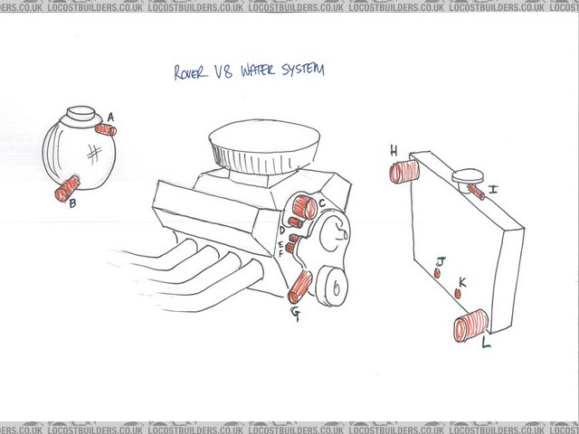
Rover V8 cooling diagram
plus I need to add 2 pipes for a heater, there is no I J or K and E and F are one as there is a electric pump and where the pump used to be is
blanked off.
So in my proposed setup I am thinking
G to electric pump, which goes to L
B tee into G then to pump.
D do I need a D ? if I have one added to the thermostat housing that will go between at the front of the inlet manifolds tee it into G then to
pump.
C to H
A to ?? I am thinking to the cross over at the back of the inlet manifolds?
EF (they are one) to one heater port.
where do I bring the heater out to ?
any thoughts on this!?
I am thinking that I will end up with something looking like this ebay add (handy time for these pics to be available!) but am considering D.
Rover V8 throttle bodies( CBR 600)
any thoughts on where I should be taking coolant temp from? I seem to have 3 places presently, 2 in the inlet manifold (yet to work out what they are
driving, could be one for the guage and one for the electric pump.. that would make sense now I have just though about it!) and one on the top hose
which I think runs the fan... So for the guage and the electric pump somewhere in the hose that the thermostat housing will be attached to?
cheers!
[Edited on 10/4/14 by Chris_Xtreme]
[Edited on 10/4/14 by Chris_Xtreme]
Irony - 10/4/14 at 06:39 PM
Hey! I drew that picture!
Chris_Xtreme - 10/4/14 at 06:53 PM
Sorry mate I was rushing at work and hopefully implied I had seen it on here. It is indeed your pic and a great one at that  I as many on here have
already done thank you for it. Sorry, I didn't mean to claim it as mine.
I as many on here have
already done thank you for it. Sorry, I didn't mean to claim it as mine.
mark chandler - 10/4/14 at 07:23 PM
You have missed the most important bit, at the front of 1 head and rear of other is a water gantry, these need joining and a small 1/4" pipe
tee'd into this taken to either the expansion chamber or top of the radiator to bubble air off the heads.
Chris_Xtreme - 10/4/14 at 08:09 PM
hi, yep I think I know what you mean, there was a point at the very top of the edelbrock manifold that when to the top of the expansion tank - A.
so are you suggesting something like this:

one weird thing I found was that there was no thermostat in the inlet manifold where I thought it should be!.. I definiatly saw the temp rise and
fall, so I will have to undo the point where the water pump used to be and see if one has been installed there..(at the very bottom of this pic) this
may negate the need for one at the top and save the question about D.
cheers
Chris
mark chandler - 10/4/14 at 08:31 PM
That's the way forward, I'm pretty sure on each side one is blanked off by the manifold so you could reduce to one outlet per side.
Chris_Xtreme - 10/4/14 at 09:28 PM
cool, just checked, on the edelbrock neither side is blanked off, the water seemed to flow around everywhere, in and out both sided front and back as
well as through the middle front to back.
so , I think I am sorted (bar finding a thermostat somewhere!)
Just thought - electric temp controlled pump = no thermostat - but there wasn't a flow restrictor either..
except for where to return the heater to?
A bit more reading leads me to think it should go and join B and go onto G.
thanks for any more suggestions.
[Edited on 10/4/14 by Chris_Xtreme]
[Edited on 10/4/14 by Chris_Xtreme]
Irony - 11/4/14 at 09:11 AM
Haha don't worry about using the picture. I am watching the thread with interest as I may do the same in the future. Why are you upgrading to
this system and what benefits are you expecting?
Chris_Xtreme - 11/4/14 at 09:24 AM
why - well that is a question! just for the hell of it I suppose. I've got two little kids that really take my time and prevent me driving the
car, so though I would do some evening work on it instead!
although, since I have had the car I have not been happy with the carb setup, far from smooth, the clutch is slipping like mad, so a load of work has
to happen. I bought the TBs from wilkingj ages ago and am just going for it.. had to save some pennys for the �700+ to bogbros to get the inlet work
done for them. I based doing this on reading started from wilkingj research.. not going to be blaming him if it fails but may be calling on him to see
if he remembers anything about the MS as he built it!
I'm not necessarily aiming to get more power, just a smooth ride and hopefully better mpg and the challenge of doing it and switching to mega
squirt.
I'm gonna start another post on here to track my progress as such, just getting a couple of things queried before I send the TBs off to BBs so I
get the correct take offs in the inlet manifold side of things.
the car is coming to bits tho
v8 to bike TB pics
Chris_Xtreme - 17/4/14 at 12:20 PM
hopefully final question on cooling setup!
anyone know if I could use the same temperature sender to power the dash gauge and also the mega squirt? (ie take 2 wired off the same point)
on my inlet manifold I a alreadt asking for 2, one for the elec water pump and the second for the dash gauge.. do i need a third?!
cheers!
scudderfish - 17/4/14 at 01:09 PM
Very unlikely to work. I have two myself, and the one for the dash gauge is really just ornamentation as the gauge/sender combo is pants. Can the MS
not run the electric pump for you?
Regards,
Dave
Chris_Xtreme - 17/4/14 at 01:23 PM
thinking about it more,, the gauge provides the + and senses how much gets through, so 2 on 1 wont work.
think i will just get a third added.. my dash gauge is pretty good, the elec pump works as it is, so I would feel happier with at least the option of
having them all separate.
I have a spare durite gauge and sender, so will use that. I just need to double check that the MS can be calibrated for any old temp sender.
cheers, Chris
scudderfish - 17/4/14 at 02:35 PM
MS1 or MS2? MS1 is a bit of a faff, but MS2 is apparently a lot easier. I just bought the right sensors at the same time as I bought my MS1.
Regards,
Dave
Chris_Xtreme - 30/4/14 at 01:03 PM
It is MS 1, I decided to buy the sensors from paul at extraefi - as he has done bike TBs on MS on rV8.
scudderfish - 30/4/14 at 02:12 PM
Phil surely That's where my MS1 came from as well.
Chris_Xtreme - 30/4/14 at 02:21 PM
um - yes that would be correct !!! Phil not Paul. far too little sleep last night - finished getting the car in the garage after getting the engine
etc out (did you see my g+ post) at gone midnight and then my boy was up for a couple of hours- doh! just on the nights you don't need.
Chris_Xtreme - 9/4/15 at 01:02 PM
quote:
Originally posted by Chris_Xtreme
hi, yep I think I know what you mean, there was a point at the very top of the edelbrock manifold that when to the top of the expansion tank - A.
so are you suggesting something like this:
one weird thing I found was that there was no thermostat in the inlet manifold where I thought it should be!.. I definiatly saw the temp rise and
fall, so I will have to undo the point where the water pump used to be and see if one has been installed there..(at the very bottom of this pic) this
may negate the need for one at the top and save the question about D.
cheers
Chris
Just thought I would report back and say the plan seems to have worked, so thanks for the help.
The car can idle nicely, get hot and the fan brings it back down again. Went for a 50 odd mile drive last night, spose the air temp was fairly cool,
but no overheating , was running at about 85 /90.
cheers all.
