GaryM
|
| posted on 20/6/09 at 05:54 PM |

|
|
Crossflow FZR 600 Bike Carb Conversion
Bike carb conversions seem to be getting very popular so i thought I have ago.
I've almost finished now so i thought I'd write up a brief description of my conversion on a Ford Crossflow 1600GT (with Kent BCF2 fast
road cam) replacing the original fitment Weber 32/36 twin choke carb. The bike carbs selected for transplanting were from a 1999 Yamaha FZR600 Fazer
and cost £10 from eBay.
I chose the FZR600 carbs (Mikunis) for a couple of reasons. The choke size (33mm) is a good match for my xflows capacity and expected power output
(there is a sizing graph floating around somewhere on the net) and (importantly for my install) the carbs are mounted horizontally on the bike so I
shouldnt have fuel float level issues when installed the same way on the car, enabling the carb intakes/air filter to protrude through the side of
the bonnet like twin 40s. An added bonus is that they dont seem that popular for bike carb conversions so can be picked up very cheaply.
 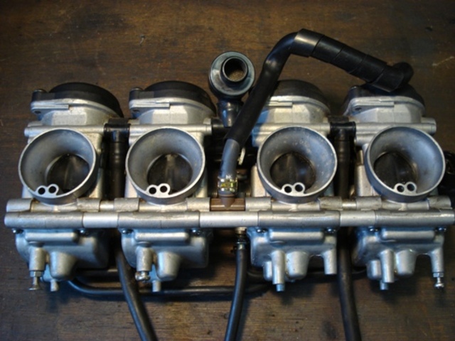
Original FZR bike carbs
The new inlet manifold had to be as short as possible in order for the whole package not to extend too far out of the side of the bonnet. At first I
built a jig that had the inlet runners angled to join the unspaced carbs but the angles were just too severe to be practical. Plan B was to respace
the carbs to be inline with the inlet ports on the head. This worked better and the jig was re-jigged to this spacing. Once happy with the spacing
and heights I prepared the inlet manifold parts. The face plate was 6mm ali marked up with an xflow inlet manifold gasket and then drilled and hole
cut. The runners were made from 38mm OD ali tube with a wall thickness of 3mm, this was as close as I could get to match the corresponding outlets of
the carbs. The parts were then tig welded together (along with a threaded coolant outlet) and some mounting brackets added at each end of the plate to
secure the carb assembly to if needed.
The carbs were disassembled cleaned and then respaced. This entailed:
1. Extending the throttle linkages by welding on some steel extensions.
2. Turning up some longer ali spacers that fit between each carb and replacing the long securing bolts with some M6 stainless studding.
3. Turning up some extended fuel unions (one with a welded T piece).
4. Extending the starter plunger link to fit the respaced carbs
Once complete, the carbs were reassembled and clamped together using the M6 studding and nyloc nuts. The fuel unions were tested to make sure they
didnt leak and throttles adjusted (by eye) so they opened and closed together.
 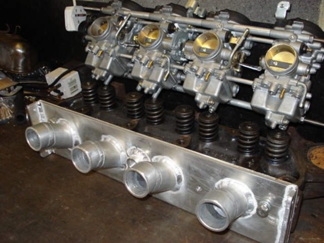
Manifold and respaced carbs
The complete assembly was then joined to the new manifold (that had already been fitted to the cylinder head) using 52mm fuel hose and hose clamps.
Fuel hose was used instead of silicon hose because hopefully there will be no reliability issues. There were no problems with the carbs/manifold
fouling the xflows dizzy as this had already been replaced by a Megajolt ignition system!
 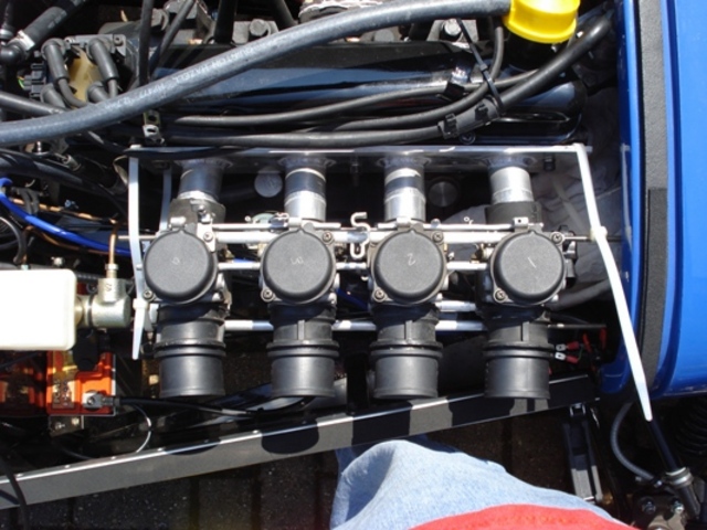
Trial fitting
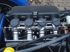
Luckily, Pipercross make a sausage filter that is just long enough to cover the respaced carbs intakes, so I made a custom back plate and used this to
fix the filter to the carbs via the original bike (carb to airbox) rubbers.
New throttle (and choke) cables where fabricated and the xflows existing mechanical fuel pump connected to the carbs new fuel inlet. At that point
there was nothing else to do but see if it worked!
I primed the carbs with some fuel (otherwise it would have taken a lot of cranking for the mechanical fuel pump to achieve the same), pulled the choke
(well starter plunger) cable, crossed my fingers, double checked where the fire extinguisher was and turned the ignition key. It fired up straight
away and settled into a lovely smooth idle. Much relieved I then tried blipping the throttle but the main jets were way to lean as it just spluttered.
Still not a bad start!
The procedure for tuning the setup(without a rolling road) involved the following:
1. Lots of time a patience
2. A set of micro drills (to redrill the main jets)
3. A wideband oxygen sensor.
First step was to tune the idle mixture (I had already balanced the carbs on a fast tickover using an inlet type balancer). Luckily all that was
needed was some adjusting of the pilot screws to achieve an AFR of about 14.7. The ticker was then reset using the carbs throttle stop adjuster.
Next step was the wide open throttle (WOT) mixture. This needed to be tested on the road (private of course). I had already opened the main jets up to
1.3mm as the original 1.15mm jet size was way to lean. I kept testing, disassembling, redrilling, assembling and testing again until I got somewhere
near a reasonable AFR of 11-13 under various WOT/rev combinations but I couldnt keep the mixture from leaning out at the higher rev ranges even after
opening the main jets up to 1.7mm! After a little research I discovered that the air corrector jet size affects the WOT mixture at higher revs so I
blocked them completely and tested again. Bingo, this time the AFR stayed below 13 right through the rev range. Unfortunately, these jets on my
Mikunis are not removable, so I drill and tapped the holes M6 and blocked them with a grub screw. I might change these for some very small M6 jets at
a later date as Im sure some air correction would be a good thing.
Last mixture setting was the part open throttle settings which are controlled mainly by the needle and needle jet. Again (luckily?) they were not
too bad (between 12-13 AFR). But I decided to drop the needles (i.e. raise the clips) one slot in the slides too lean out the mixture a bit more and
now have an AFR of 14.7 at 30-40 mph cruising. Im not sure if this is safe (?)so I may go back to the original needle clip positions after Ive dome
some faster cruising speed tests.
On overrun the wideband sensor does show AFR readings in the high teens (and the exhaust makes that excellent popping sound) but I guess the engines
not under load so thats OK?
I still need to do some more testing but I think Im 98% there. Oh and yes (in case youre wondering) it does make a BIG difference to the engines
performance!!
Thanks to all those on the forum (especially Dave Jenkins and Robocog) for any advice given, also Bogg Bros and most of all Huey, the best
engineer/fabricator in the UK.
xflow bike carbs 1
[img][/img]
|
|
|
|
|
goodguydrew
|
| posted on 20/6/09 at 05:59 PM |
|
|
That was an excellent post. Thanks for sharing it. 
[Edited on 20/6/09 by goodguydrew]
|
|
|
omega0684
|
| posted on 20/6/09 at 06:10 PM |
|
|
very tidy indeed, great post, have you taken it out yet? is there much difference in performance?
edited: sorry just read the last part of the post again
[Edited on 20/6/09 by omega0684]
|
|
|
David Jenkins
|
| posted on 20/6/09 at 08:45 PM |
|
|
That looks like a very neat bit of work - well done!
cheers,
David
|
|
|
TbirdX
|
| posted on 21/6/09 at 06:01 PM |
|
|
Will it get a rolling road at some point, be interesting to see the actual difference it made.
|
|
|
GaryM
|
| posted on 30/6/09 at 09:34 PM |
|
|
I hope to get the car on a rolling road at some point, if for no other reason than to map my Megajolt properly.
It's not been on a RR before so I have no base line bhp figure to quantify any gains.
However, I will be more than happy to publish the results after I find a suitable RR at a suitable price!
Any suggestions?
[Edited on 30/6/09 by GaryM]
|
|
|
GaryM
|
| posted on 3/10/09 at 11:50 AM |
|
|
Update
As I mentioned in the main post, I felt I had the carbueration about 98% correct. The last 2% being an issue with the Fazer carb's standard
0.8mm (non-removeable) air correction jets meaning the AFR read lean at high revs WOT.
I tried blocking the air correction jets completely which stopped the mixture leaning out but introduced a loss of crispness in carb response and
richened the mixture at 25% onwards throttled openings. I could have compensated for this by reducing the main jet sizes and dropping the needle
heights but I felt the air correction circuit was designed into the carb for a reason so I should retain it if at all possible.
In the end the answer was fairly straight forward. I tapped a 6mm thread into the opening of the air correction passage (on each carb) and
experimented adding some small size 6mm jets until the weakness (as discribed above) dissappeared. The original air correction jet was retained (coz I
couldn't remove it!) but it didn't matter as it was larger than the extra jet I was introdcuing to the circuit.
In the end 0.4mm jets did the trick.
The carbueration is now spot on and i'm looking forward to getting the ignition mapped on a RR.
Cheers
Gary
|
|
|
Silvo
|
| posted on 25/10/15 at 06:33 AM |
|
|
Air correction jet
Hi Gary great write up of carb conversion - I'm in the process of going through this and just wondered which of the two small jets on the inlet
side is the air correction jet ? - thanks - neil
|
|
|