FuryRebuild
|
| posted on 21/6/12 at 12:27 PM |

|
|
I'm note sure at the moment - my front suspension's off and it won't go back on for a we while. I'm waiting from some bits
from the powder coaters to come back.
I used to have the arches and didn't have much grief, but number 1 and the others did angle back - in essence they all met at the joint of 2 and
3.
On my old exhaust they were all about the same length apart from 4, which was 100mm shorter - crap really.
From what I can gather, getting them within an inch is a great result, and 2 isn't *so* bad. 4-5" on the other hand is crap.
When all you have is a hammer, everything around you is a nail.
www.furyrebuild.co.uk
|
|
|
|
|
Furyous
|
| posted on 21/6/12 at 02:17 PM |
|
|
quote:
Originally posted by FuryRebuild
I'm note sure at the moment - my front suspension's off and it won't go back on for a we while. I'm waiting from some bits
from the powder coaters to come back.
I used to have the arches and didn't have much grief, but number 1 and the others did angle back - in essence they all met at the joint of 2 and
3.
On my old exhaust they were all about the same length apart from 4, which was 100mm shorter - crap really.
From what I can gather, getting them within an inch is a great result, and 2 isn't *so* bad. 4-5" on the other hand is crap.
Funnily enough, I've just finished tacking them up to the collector and purely by chance, 1-3 are within an inch of each other and #4 is about
4" short. If I had any spare bends I'd have a go at making it a bit longer.
|
|
|
FuryRebuild
|
| posted on 21/6/12 at 02:49 PM |
|
|
that sounds exactly like the way my pinto was. weird.
When all you have is a hammer, everything around you is a nail.
www.furyrebuild.co.uk
|
|
|
R1 STRIKER
|
| posted on 21/6/12 at 06:55 PM |
|
|
Hows it looking for height and sump clearance? Just planning a new striker build and looking at this as an option. Hate the tall striker bonnet though
so would want to fit it under standard bonnet.
Would love to build it in phoenix but the cost of the bodywork puts me off!
|
|
|
FuryRebuild
|
| posted on 21/6/12 at 06:56 PM |
|
|
I should have 4"
Given a good push at the car this weekend I want to get the suspension on for a dry build up to check for interference.
I should be able to give you an accurate ground-clearance measurement then.
cheers
Mark
When all you have is a hammer, everything around you is a nail.
www.furyrebuild.co.uk
|
|
|
FuryRebuild
|
| posted on 22/6/12 at 08:28 AM |
|
|
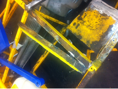
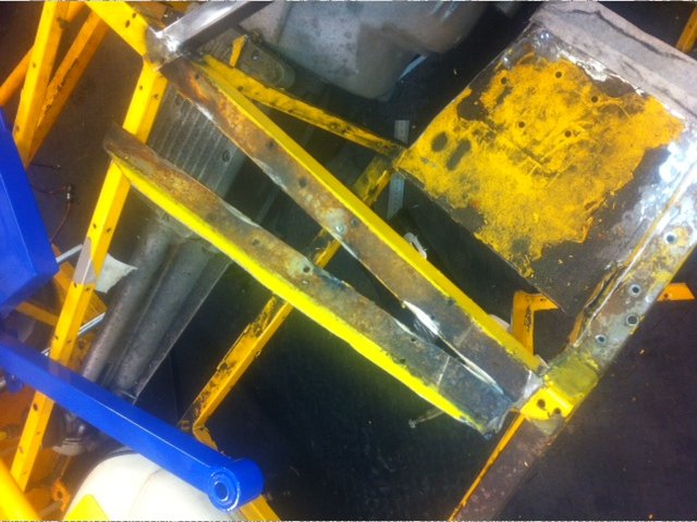
Here's an interesting thing I discovered though - This picture shows the remaining footwell plate (lower left diagonal) separated from the
cross member (diagonal above it). To get this pic I ground the welds out and peeled one away from the other. When separating them I found that rust
had creeped in. There's not much but there's no powder coat where in there to protect things. I think this may be the slow creep of
trapped moisture rather than ingestion. However, it's there and would over a number of more years caused more pain. It's probably worth
noting that this is 10 years worth of grief, so maybe the correct plan is 'do nothing', or once i've welded the new parts together,
smear a little metal putty along the edges to get a seal before i send it off for coating.
Description
When all you have is a hammer, everything around you is a nail.
www.furyrebuild.co.uk
|
|
|
Furyous
|
| posted on 22/6/12 at 01:12 PM |
|
|
It looks like your #1 exhaust port is slightly further back than my #2 port, in which case you would probably be able to go straight out over the
chassis rail. My #2 header had to go back just a little bit to clear the arch.
|
|
|
FuryRebuild
|
| posted on 22/6/12 at 01:43 PM |
|
|
I had wheelarches in my first incarnation, but when I stuffed it at harewood the bonnet was a write off (amongst other things).
I went for the light-weight bonnet second time around and didn't bother with arches.
When all you have is a hammer, everything around you is a nail.
www.furyrebuild.co.uk
|
|
|
FuryRebuild
|
| posted on 25/6/12 at 09:55 AM |
|
|
Fury Duratec Sump's finished (dipstick action)
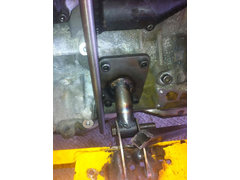
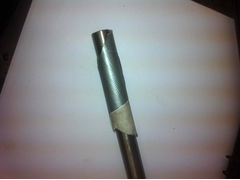
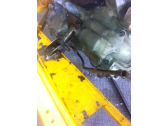
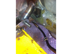
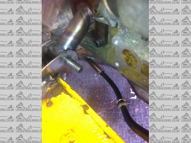
So, just about the last job to do on the sump is to get the dipstick path routed. As per flak's instructions, I bought some 15mmOD stainless
tubing to match the hole cut in the side of the sump. My original plan was to route the pipe vertically up the side of the engine and emerge between
the throttle bodies. As you can see from the pic below, this isn't a great route, and runs far too close to many things, including the engine
mount bolts, and one of the water pump housing take-offs.
Description
So, I needed to either go for a simple route up, hoping i could get the angles so precise that it missed everything, or find a better way. Digging
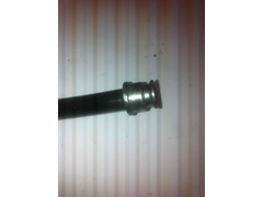
through the heap of stuff I'd taken off the original engine, I extracted the dipstick tube (just pulls out of the sump - held in with an o-ring)
and took a look at the convoluted routing it takes - i found it to be good.
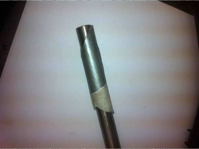
Now that I had a plan to take a route, i needed to plan the take-off from the block. Wrapping some paper around the pipe and using duck tape to make
it rigid, i now had a template of the pipe that could be cut with scissors until I had the angle right without risking multiple chops into the steel.
Here's the result:
Description
Description
Note that it comes off the sump at a slight angle away from the sump to move the dipstick into the void space there. I've kept the template in
case i make a sump for anyone else (Furyous is getting one if he likes this design).
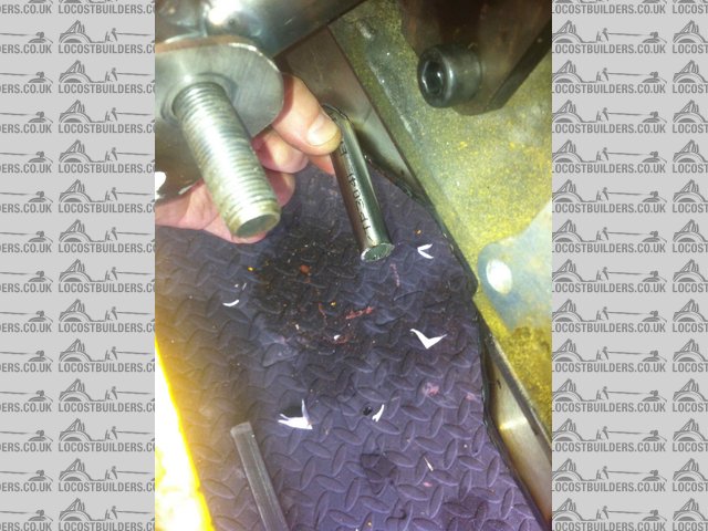
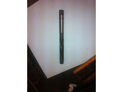
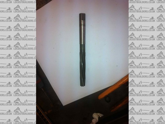
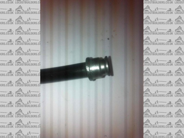
Next came the plan to fit the dipstick tube onto the sump take-off pipe. When measured, the tube is about 0.3mm short of half an inch, and the ID of
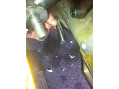
the pipe is about 11.5mm, and i happen to have had my trusty 1/2 inch reamer ready. In order to make the dipstick pipe fit the sump, I reamed out the
end of the take-off pipe to 1/2 inch. This was a little tricky, needing to position and clamp the pipe in the drill-vice, and then gently ream down
and back (lots of cutting spray) in order to take it out. The end result is that the dipstick tube fits nicely into the end and has a little swivel
room:
Description
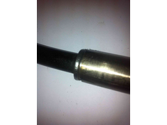 
Description
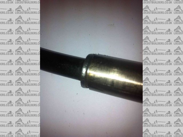
I also cleaned the end up ready for welding. However, I decided not to weld it for a couple of reasons - no going back after putting that tack in,
especially if it's routed wrongly, and i'd also be welding stainless to mild. In the end, I decided that the better solution by far would
be to fit it all back to the car, make a support bracket for the tube so it hugs the engine nicely, and then epoxy it in. It will be a very strong
solution, easier than a weld, and will give me a couple of minutes wriggle time before it goes off.
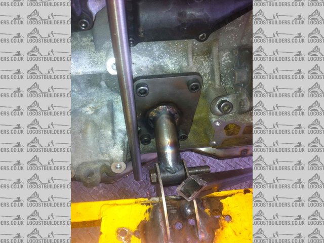
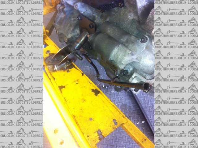
Description
Here's the final run up through the void. In the background middle-right you can see the starter motor bolts, and i'm going to fabricate a
bracket to go onto this bolt as well - job done - dipstick now properly secure.
Here's another picture from a slightly different angle showing the take-off from the pipe, because i'm so pleased with it. It's a
good thing when something runs neatly and without fuss - generally simple is always best, and not necessarily the easiest to achieve
Description
Description
When all you have is a hammer, everything around you is a nail.
www.furyrebuild.co.uk
|
|
|
FuryRebuild
|
| posted on 6/11/13 at 02:44 PM |
|
|
transmission tunnel Mould Making - lessons learned
As ever, this post is replicated on my blog, where there's more content as well.
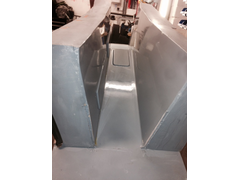
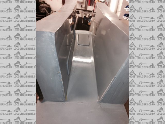
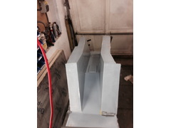
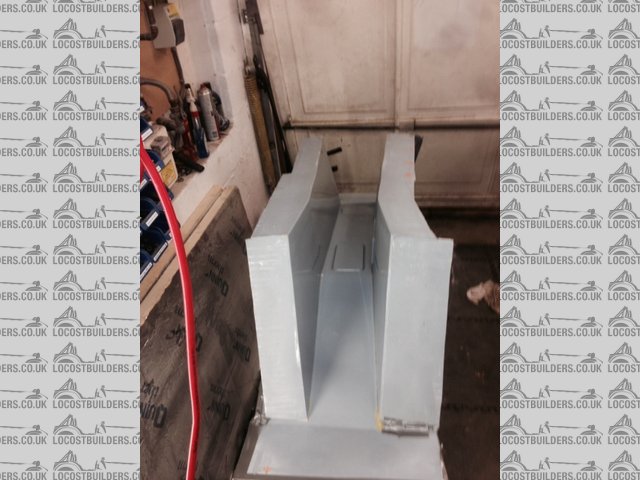
Wow this mould is becoming a saga but its worth it to get it right. So, as you can see from the two pictures, the mould is finished and ready to
pull a part. It's worth namechecking carbonMan here - he's been mentoring me through this process with extreme patience.
Description
Description
So, the plan to get a part out of this mould was as follows:
- do a trial bagging session to understand how the bag falls in under vacuum and get a good handle on the pleats. write off the bag afterwards.
- lay in the first two layers and set them this gives me a chance to examine the the quality of the finish and lets me decide if I like it before
continuing. This tunnel is going to be utterly structural and will have the thick end of £250 of cloth and resin going in there, so I want to be sure
it is right.
- If I like it, I can put the part back into the mould and infuse the further layers into it.
But
DISASTER.
The mould isnt remotely air-tight. It boils down to a fundamentally bad assumption on my behalf, namely that the wood I ordered would be vac-tight.
Its not. I did a test on a patch of it and couldnt get it to hold vac at all. And thats before I go investigating the other bits of it where it
mates and the flanges for the three-piece aspect of it.
So, rather than faff about for a week and get nowhere and waste a load of bagging material, I called Warren for suggestions.
His idea was a step beyond my initial one (throw it into the skip) which was to lay a chopped strand mat part in there (no need for a vacuum seal with
simple wet lay) and then take a mould from that.
This has many advantages:
- 3 layers of 450g CSM is cheap
- I can trial fit the part to the car. Its not going to be anything like the final part (13mm thick) but will give me ideas
- its a one-off, so best bet is get the part finish as good as possible and then I can use a standard moulding kit to make the final, vac tight
mould.
Lessons Learned
- I tried a hybrid technique of using part making material for mould making, which didnt work
- you can use any old cheap bits for pattern making but moulds require precise application of the right materials and chemistry for resin infusion
- I have a good mould but nothing like strong enough or sealed enough for epoxy resin infusion
- cut your losses
- growth through pain. 80% of learning is experiential I have learned so much getting hands-on like this.
So, I can now see a positive from this, which is I will have a part that can be wrangled into the shape I need and surface finished. Then I can make
the right mould, out of the right materials.
When all you have is a hammer, everything around you is a nail.
www.furyrebuild.co.uk
|
|
|
ceebmoj
|
| posted on 7/11/13 at 12:22 AM |
|
|
very interesting it shows how hard it is to get to grips with. I was thinking the other day about making a composite structure to support my side pods
but think I will give it a miss now. ;-)
|
|
|
FuryRebuild
|
| posted on 7/11/13 at 12:27 AM |
|
|
Well, this was a silly "jump in at the deep end ambitious" kind of thing. The strong flat panels I've made we're way easier.
It is very satisfying when you get it right
quote:
Originally posted by ceebmoj
very interesting it shows how hard it is to get to grips with. I was thinking the other day about making a composite structure to support my side pods
but think I will give it a miss now. ;-)
When all you have is a hammer, everything around you is a nail.
www.furyrebuild.co.uk
|
|
|
me!
|
| posted on 7/11/13 at 07:21 AM |
|
|
Out of interest- why are you doing a structural fibreglass tunnel?
|
|
|
FuryRebuild
|
| posted on 7/11/13 at 08:29 AM |
|
|
Hi
Simple answer is that I'm not 
I'm making a fully structural composite tunnel. If you take a look at this post,
you can see how I was replacing the ali panels with carbon ones in order to save weight. However, I found on these panels that the positioning of the
mounting holes was too near the edge of the carbon panel to actually give a structural attachment.
I can see why manufacturers use ali panels - they're easy to cut and shape - the sides of the tunnel are actually quite a subtle but complex
intersection of many planes. To make this work in Ali, all you need to do is cut it, rivet and tap into place with a soft hammer. However, you are
using soft rivets on soft panels which means they don't add any kind of structural strength for the weight - their job is to keep the rain
out.
I then had two options in order to use the panels I'd made - either weld in lugs at the top of the tunnel so I could put mounting holes further
inside the panel, (add weight) or do the right thing, which is cut out the top rails and make a fully structural 3D tunnel. then I get the following
benefits: lighter, stronger as a stand-alone part and if properly bonded in place then it will actually strengthen the chassis considerably.
The layup from the outside in, will probably be:
- 200gsm profinish carbon outside layer
- 400gsm carbon inner layer
- 200gsm e-glass layer
- 200gsm uni-directional (front to back) carbon
- 200gsm e-glass layer
- 200gsm carbon
- 10mm closed cell foam (quite rigid)
- where I have curves, I'll use three layers of 3mm soric to get around the corners rather than use the closed cell foam
- 200gsm carbon
- 200gsm e-glass layer
- 200gsm uni-directional (front to back) carbon
- 200gsm e-glass layer
- 200gsm uni-directional (front to back) carbon
- 2* 350gsm aramid
This equates to 7 layers at 200gsm either side of the core material which (by the time i've cut the top rails out) will be lighter than the
original, and will be bonded into the chassis using the correct adhesive (which will make the bond stronger than the steel). 7 layers is typical for a
structural tub layout (very similar to an F1 layup).
If you look down the tunnel you can see panels set into the mould which will eventually be access panels, so even though it's bonded in for
good, you can get to the fuel tank, prop and other bits and pieces.
Once the tunnel is made, I will then make structural horse-shoe ribs (they only need to be 20mm dia) and will bond them in. Finally, I will put a rib
in the back over the prop which will be designed in situ. This rib will give the prop 10mm clearance and will double as a prop-catcher. I will set
hard-points into the rib at the bottom so I can then make a mating piece to come into it and bolt in from below to complete the prop-catcher. Imagine
how a big-end bearing bolts together: that's what I'm aiming for.
Bearing in mind my prop is part of an IRS setup, it doesn't really move around much relative to the car, and all the energy is angular, not
linear. As such the prop-catcher/strengthening rib will be made in aramid with a 10mm core and Ali hard-points set it.
This should give me massive amounts of strength for less weight.
quote:
Originally posted by me!
Out of interest- why are you doing a structural fibreglass tunnel?
When all you have is a hammer, everything around you is a nail.
www.furyrebuild.co.uk
|
|
|
scudderfish
|
| posted on 7/11/13 at 10:39 AM |
|
|
quote:
This should give me massive amounts of strength for less weight.
And be cool as f**k 
|
|
|
FuryRebuild
|
| posted on 7/11/13 at 11:32 AM |
|
|
(blushes), why scudderfish, you say the kindest things.
I'm not stopping there - the next thing is to replace the floor and back and side plates with a tub made in a similar manner to the transmission
tunnel. the only original steel left will be the bottom and top side rails. I'll be sitting in a fully composite tub at that point.
This is all learning and apprentice pieces (for a 44 year old bloke). who knows where this will lead in 5 years time. I don't think you can even
have meaningful conversations with people unless you've acrually got your hands dirty.
And in the locost tradition, DIY is important.
quote:
Originally posted by scudderfish
quote:
This should give me massive amounts of strength for less weight.
And be cool as f**k
When all you have is a hammer, everything around you is a nail.
www.furyrebuild.co.uk
|
|
|
scudderfish
|
| posted on 7/11/13 at 12:35 PM |
|
|
Have you ever been in touch with Rob Collingridge? (http://www.robcollingridge.com/) I don't think he ever comes here, but he has an R1 Fury and
is now toying with ideas to make a sub 400kg replacement with a composite chassis. I think you'd get on well
|
|
|
me!
|
| posted on 7/11/13 at 03:23 PM |
|
|
Haha, fair enough! Now get stuck in, I want to see the result :-)
|
|
|
ceebmoj
|
| posted on 7/11/13 at 07:10 PM |
|
|
quote:
Originally posted by FuryRebuild
This is all learning and apprentice pieces (for a 44 year old bloke). who knows where this will lead in 5 years time. I don't think you can even
have meaningful conversations with people unless you've acrually got your hands dirty.
I look forward to seeing the composite tub you build next. :-)
|
|
|
HowardB
|
| posted on 7/11/13 at 07:57 PM |
|
|
quote:
Originally posted by ceebmoj
quote:
Originally posted by FuryRebuild
This is all learning and apprentice pieces (for a 44 year old bloke). who knows where this will lead in 5 years time. I don't think you can even
have meaningful conversations with people unless you've acrually got your hands dirty.
I look forward to seeing the composite tub you build next. :-)
me too,.. I like the idea of something that wont rust,..
Howard
Fisher Fury was 2000 Zetec - now a 1600 (it Lives again and goes zoom)
|
|
|
FuryRebuild
|
| posted on 7/11/13 at 09:11 PM |
|
|
My confidence is growing to the point where I'm ready to remove the diagonal tubes as well - if I double skin that panel with carbon with a good
thick core, the diagonal isn't needed anymore.
RaceCar Engineering had an article recently that stated that for a competent driver who laps consistently, every 2.76 KG is worth 0.1s from the lap
time.
To quote the venerable chapman - "just add lightness".
When all you have is a hammer, everything around you is a nail.
www.furyrebuild.co.uk
|
|
|
ceebmoj
|
| posted on 7/11/13 at 09:48 PM |
|
|
quote:
Originally posted by FuryRebuild
My confidence is growing to the point where I'm ready to remove the diagonal tubes as well - if I double skin that panel with carbon with a good
thick core, the diagonal isn't needed anymore.
RaceCar Engineering had an article recently that stated that for a competent driver who laps consistently, every 2.76 KG is worth 0.1s from the lap
time.
To quote the venerable chapman - "just add lightness".
Out of interest with the kit you have and tools available to the average home builder, how much to you think a car built with a composite tub would
weigh and cost to manufacture?
|
|
|
FuryRebuild
|
| posted on 11/11/13 at 09:25 PM |
|
|
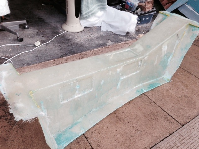
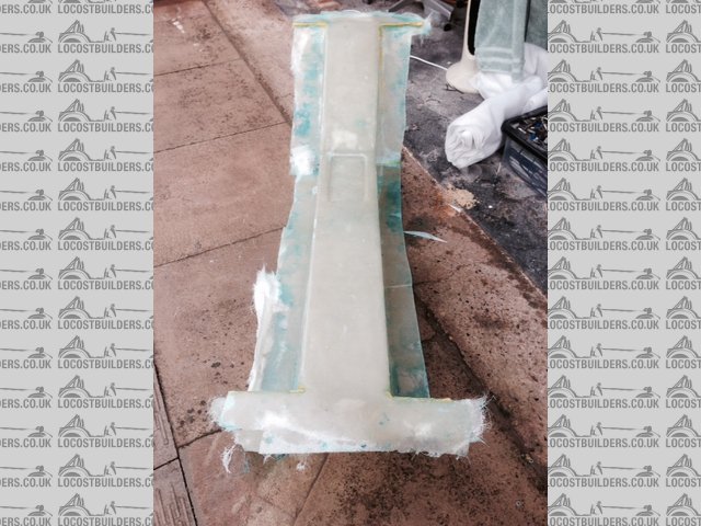
Proud father of a ... transmission tunnel buck
As ever, this post is also on my blog, as a lot of other stuff.
Description
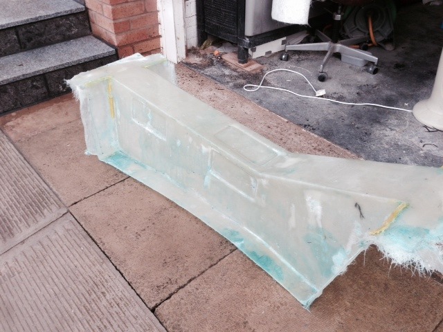
So, I managed to get the wet-lay done last night. It took a couple of hours and about 4 litres of resin. The stuff I was using was simple non Lloyds
approved resin from Leeds Fibreglass Supplies which worked well. I mixed it at 2% catalyst and in 2L batches. It only started to gel-off right at the
end of the tub, which was a success. Also, the resin was pink not blue, and turned gray as the catalyst started to activate.
Description
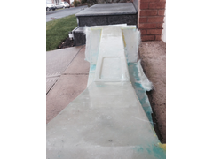
The part came out of the mould in about 90 minutes which was a fair fight. I'm really glad I used PVA again because it's water soluble.
You just get a thin wedge in (I used a plastic bog-spreader) and spray some water down. It slowly starts the separation and all is well. Keeping forth
the birth metaphor, you can see the birthing remains stuck to the part. PVA is like a skin (rather than EasyLease which is a chemical barrier).
Description
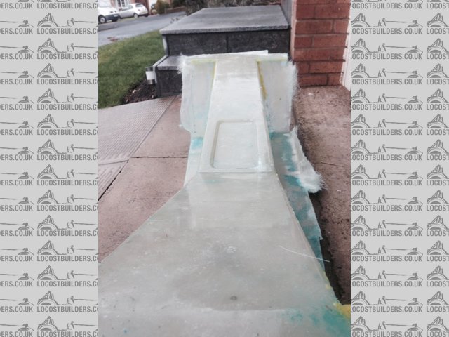
Above is a nice shot down the top of the tunnel, or chute, or birth canal, if it were. What you can't see is the quality of the surface finish.
It's actually quite shiny but there's little sunlight to reflect off it (cloudy overcast day).
Description
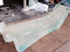
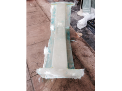
It's not all perfect though - no matter how much resin I poured on and how manic I got with the bubble-buster (i.e. special wet-lay roller) I
just couldn't sort some of the white patches and it's come through the mould. There's the odd bubble between the layers (which I
will live with - this is the master buck, not the part) but there's also some dry patches of glass on the face.
Next steps are to dress the surface issues and then seal for a part ... can't wait.
Lessons Learned
- Making a master part from the failed mould was the right thing to do. Not only am I confident I have a good part but it was a step forward after
the frustrations of the mould not working due to bad mould material choices.
- Thoroughly wet through the first layer. Don't get resin on most of it and then try and catch up later. If I'd done this, even though I
may still have had bubbles, I wouldn't have had dry spots.
- Filleting wax is great.
- I rushed this a bit because I was concerned resin would be gelling off. Not so.
- 2% catalyst was right for this part in these temparatures. I was working with "winter catalyst" which is more aggressive.
- Laying large (300mm) strips down the side into the middle with lots of overhang into space means the glass is balanced on top of the part and
doesn't fall down into the mould. Once set, the overhang can be cut off and reused in smaller bits.
- Having lots of supplies (i.e. spare glass and resin) means you're not fretting about running out (which I did last time) which meant
rushing.
- Styrene stinks, and gets through the brick-work from the garage into the house. I need to think about what to do here.
When all you have is a hammer, everything around you is a nail.
www.furyrebuild.co.uk
|
|
|
Furyous
|
| posted on 11/11/13 at 11:24 PM |
|
|
What are the inset rectangles for? Strength?
|
|
|
FuryRebuild
|
| posted on 11/11/13 at 11:30 PM |
|
|
Good question. They're going to be access hatches. I will take a mould of the hole to make the part that fits virtually flush in the hole, then
I can remove it and have a flush access hatch. The tunnel is going to be bonded in for good so access needs to be there in advance.
I won't remove the entire part of each hatch. I will leave a flange (with inset hard points) for the hatches to bole to.
When all you have is a hammer, everything around you is a nail.
www.furyrebuild.co.uk
|
|
|