coyoteboy
|
| posted on 30/4/12 at 12:35 AM |

|
|
Engine tilt
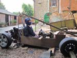
In my current plans I'm trying to keep the CofG low but if I wish to keep straight-ish driveshafts on the IRS I'll have to have the engine
a lot higher than I really need it (about 100mm). If I drop it I'll have a notable angle on the shafts, which could well argue with me. So
I'm considering leaning the whole engine and transmission forward to drop the engine at the front while keeping the diff highish. I'm just
on a scout for some images of my engine showing it's oil pickup location but the bulk of the sump is at the front so I'm guessing it will
be there and shouldn't cause pickup issues and the valley drain point between banks is at the front but so's the crankcase vents.
Anyone else come across this issue, how did you find best to deal with it? What's the max angle you've used on a set of FWD driveshafts?
I've seen allowable angles up to 40 degrees and constant angles up to 15 but I'm interested in personal experience rather than specs.
|
|
|
|
|
pewe
|
| posted on 30/4/12 at 08:10 AM |
|
|
If it's any help Lancia used to cant their FWD Beta engines over at 22degrees to reduce bonnet height.
Having reversed that to fit the Voulmex engine vertically into mine the items for consideration were:-
Oil pump pick-up
Sump shape and baffling
Dipstick calibration
Inlet tract (carb)
Cam boxes oil feed and drain
If I recall any others I'll drop you a U2U.
HTH
Cheers, Pewe10 
|
|
|
hughpinder
|
| posted on 30/4/12 at 09:24 AM |
|
|
The zetec is mounted tilted forwards 12 degrees in a standard mondeo (from my donor anyway 1997 spec). I have inclined mine to 22 degees and this
gives straight drive shafts with 195/50/15 wheels/tyres and 140mm ground clearance, Its not on the road yet. but I talked quite a lot with the guys
who build the onyx mongoose who had their engine at more like 40 degrees, and they had horrendeous problems under braking, with the oil from the sump
being thrown up the bores and making the engine smoke a lot. They managed to cure this with extra baffles in the sump, and I will also cut the sump
pan so the bottom is flat , and modify the oil pick up loation, all of which I also expect to do. If I find in practice this still gives problems I
will probably go to a dry sump or accusump set up.
Regards
Hugh
|
|
|
coyoteboy
|
| posted on 30/4/12 at 10:21 AM |
|
|
Cheers folks, some good points there - I hadn't really considered oil being thrown up the bores on braking, a little more investigation is
needed I think. Any more points welcome!
|
|
|
coyoteboy
|
| posted on 30/4/12 at 10:29 AM |
|
|
Oil pickup is right at the front. I'll play in SW and see what sort of angle I need to get it "low enough".

[Edited on 30/4/12 by coyoteboy]
[Edited on 30/4/12 by coyoteboy]
|
|
|
pewe
|
| posted on 30/4/12 at 03:37 PM |
|
|
To reduce oil surge I made up a windage tray and welded it inside the sump as well as increased baffling.
Suggest you have a look at Guy Croft as there's a mine of information about preparing competition engines (even
more in his latest book if you can afford it!).
Cheers, Pewe10
|
|
|
coyoteboy
|
| posted on 1/5/12 at 10:12 AM |
|
|
Looking at the "wing" sump he has modified to be better, that's pretty much as mine is now, though I'll have to check the
baffling which I think will probably be minimal in mine. Same overall hammerhead shape though.
|
|
|
coyoteboy
|
| posted on 2/5/12 at 01:16 AM |
|
|
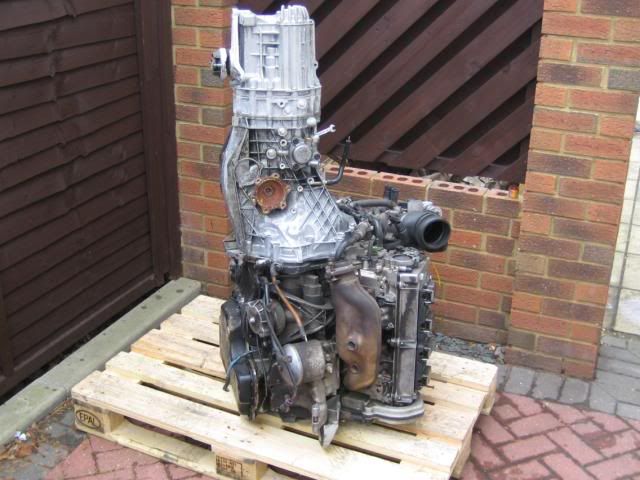
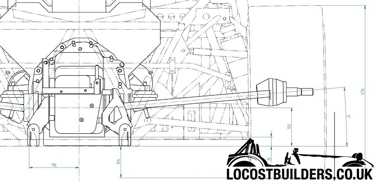
To get an idea of what I'm contending with... 
ABZ with 01E
|
|
|
hughpinder
|
| posted on 2/5/12 at 07:24 AM |
|
|
Assuming the drive shats come out at the circles near the engine, I think you have a serious challenge there to get that up to wheel centreline! I
have a vague memory that some aircraft ran upsidedown engines, but god knows what mods you would need for that. The worst problems will be braking
hard and cornering when going downhill, when all the oil will be at the front of the engine and at one side. It may be easier, but more expensive, to
dry sump it.
Regards
Hugh
|
|
|
coyoteboy
|
| posted on 2/5/12 at 10:16 AM |
|
|
I'm seriously contemplating either flipping the diff and transmission at this stage, just not sure if it's possible with the casing. I
need to re-check the dimensions though, while the outer casing on that pic is just a guide, it does suggest the input shaft is almost poking out of
the top casing, which it isnt - wondering if I've failed to fix a dimension correctly.
Actually, seems to match
[Edited on 2/5/12 by coyoteboy]
|
|
|
Doug68
|
| posted on 2/5/12 at 12:36 PM |
|
|
Edited post now I see the picture above...
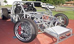
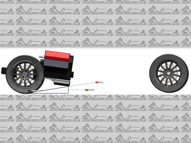
This is my setup...

This gives about 5 degrees at normal ride height. The engine is as low as it can go in the car. I don't think yours will be dimensionally much
different so I'd check the 15 degrees again.
Next edit...
I think that's an Audi box? Which will be a PITA to flip. I'd like to be wrong but I don't think its ever been done you'd
need to flip the box then flip the diff, the diff I am not sure is possible.
[Edited on 2/5/12 by Doug68]
[Edited on 2/5/12 by Doug68]
Doug. 1TG
Sports Car Builders WA
|
|
|
Doug68
|
| posted on 2/5/12 at 01:03 PM |
|
|
Also check out this thread:
http://forum.savarturbo.se/viewtopic.php?f=21&t=21458
The guy appears to be using the same combo as yourself, and seems to be able to work with the drive shaft angles arrived at.
Its an awesome thread also for inspiration.
Doug. 1TG
Sports Car Builders WA
|
|
|
coyoteboy
|
| posted on 2/5/12 at 05:04 PM |
|
|
Cheers, actually your diff looks like it sits potentially lower than mine. What wheel size are you planning to run? My final diam I think is likely to
be 628mm unloaded. This gives, assuming I keep shafts straight and assuming a 100mm ground clearance gives me 214mm between base of chassis and
diff/shaft centre. There's 100mm from the centre of the diff to the bottom of the sump lower section which is a distance of about 747mm away. If
I drop the front of the sump 100mm (which significantly lowers the C of G of the engine by about 70mm but raises the tranny c of g by about 30mm) I
tilt the whole lot at ~7.7 degrees, which isn't too bad I guess. I guess I can get away without flipping the box then. Good job as it was
starting to look impossible when I looked at the diagrams, the diff being the key issue as you say.
In the thread linked, which is pretty nice for inspiration (though I can see a number of things I'd have done differently, hindsight is amazing
isnt it!) he seems to have the whole system leaning backwards a few degrees, at least on one photo?!
[Edited on 2/5/12 by coyoteboy]
|
|
|
Fred W B
|
| posted on 2/5/12 at 05:22 PM |
|
|
I'm using an audi box, and plan to run the driveshafts significantly uphill. I see so many down sides to positioning the engine high just to get
straight axles.
I suggest you go to maybe 10 degrees of drive shaft angle at max bump and see how that works out. How much wheel travel are you planning?
Cheers
Fred W B
You can do it quickly. You can do it cheap. You can do it right. Pick any two.
|
|
|
coyoteboy
|
| posted on 2/5/12 at 08:54 PM |
|
|
I'm planning maybe 100mm travel total, the majority in bounce. The problem with running high static angles on the shafts is I've seen
dozens of reported failures from very low torque applications with tripod joints (same as the audi inners) with relatively small shaft angles, so
I'm trying to keep as straight as possible. I've got to put some real masses into the model and see exactly how much the C of G difference
will be and I suppose eventually that has to be combined with the suspension calcs but I'm unsure if in a mainly-track-partly-road based car
I'll notice any difference from a nose-low position versus an "all low" position.
What engine do you have on the audi box?
|
|
|
Doug68
|
| posted on 3/5/12 at 07:50 AM |
|
|
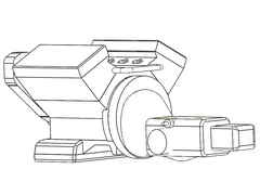
The attached picture might help.
Also use Porsche 930 CV joints, these are the ones used by serious off road buggy types as they are very strong and have a
large angle they will work at i.e. over 20 degrees, this varies by supplier though.
I made adapters to go on the box to get to the 930 bolt pattern which is larger than the Audi on my 012 at least. I'm sure the trans will break
before the CV's do.
[Edited on 3/5/12 by Doug68]
Doug. 1TG
Sports Car Builders WA
|
|
|
coyoteboy
|
| posted on 4/5/12 at 04:15 PM |
|
|
That's a nice transmission model, did you draw that by hand?
|
|
|
Doug68
|
| posted on 4/5/12 at 11:41 PM |
|
|
It just a drawing extracted from the 3D model I'd built of the design the car, the (crude) model I have of the trans itself I made from
measurements I took off it.
Doug. 1TG
Sports Car Builders WA
|
|
|
coyoteboy
|
| posted on 4/5/12 at 11:53 PM |
|
|
You have more patience than I have with modelling, I got bored and just included the key dimensions lol.
|
|
|
Doug68
|
| posted on 5/5/12 at 11:37 AM |
|
|
quote:
Originally posted by coyoteboy
You have more patience than I have with modelling, I got bored and just included the key dimensions lol.
Ha ha, I used to travel a lot with work, so it was either get drunk each night or do something useful with the time.
Besides you can work through a lot more iterations of the design in CAD than in the shed, then hopefully do it right firstime when it comes to cutting
metal.
What is the PCD on the output flange? It looks like the centering ring is on the inside of the bolts? On mine its a step on the outside. If you let
me know the dims i may have the time to work up a variation on the 930 adapters I made to suit what you have there.
Doug. 1TG
Sports Car Builders WA
|
|
|
coyoteboy
|
| posted on 21/1/15 at 01:08 PM |
|
|
Been a while, back into this.
Looks like 8 degrees would cut it, and the oil intake is pretty heavily baffled and sumped off. I think it might be OK but I'm also tempted to
reduce it by running uphill shafts too as a 50:50, primarily so I can keep the aesthetically pleasing "level heads" look.
Still very concerned about loading production CVs while significantly in bend but I can't find much quantifiable about this just yet.
Engine cant
[Edited on 21/1/15 by coyoteboy]
|
|
|