Cobra289
|
| posted on 16/8/08 at 09:50 PM |

|
|
quote:
Originally posted by hellbent345
how does that hub stay on? im interested to know so i can see if i can redesign for a rear steer system? i need to know how the stub axle passes
through the bearing and is held on? thanks
alan
Change the Sierra hub to rear steer would be easy due to the funny design of FORD.
Although the steering location should be designed in the proper way, to have the correct values of different parameters.
"Bump steer" is one of the classics but more other parameters should be take in account.
The stub axle is different than the normal stub axle design, we can say that these hub is a self containing, sorry but I don't have a section
drawing.
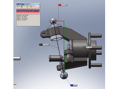
The parameters used are from a drawing posted at this forum:
http://www.locostbuilders.co.uk/viewthread.php?tid=90788
My translation to SW can be seen at the next picture.
Rescued attachment KPI_01.JPG
https://forocoches.com/foro/showthread.php?t=1699619
|
|
|
|
|
Cobra289
|
| posted on 16/8/08 at 09:52 PM |
|
|
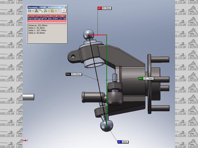
Lets see if I can post more pictures.


As you can see the Ford design is a bit confusing, probably was a manager decision to get rid of a pile of stock.
The Caster is made to have a rear steering system but the installation and design at the car [sierra] was with a front steering.
To get a nice Caster with a front steering you need to rotate the hub by a lot.
[Edited on 16/8/08 by Cobra289]
[Edited on 16/8/08 by Cobra289]
https://forocoches.com/foro/showthread.php?t=1699619
|
|
|
Cobra289
|
| posted on 16/8/08 at 10:10 PM |
|
|
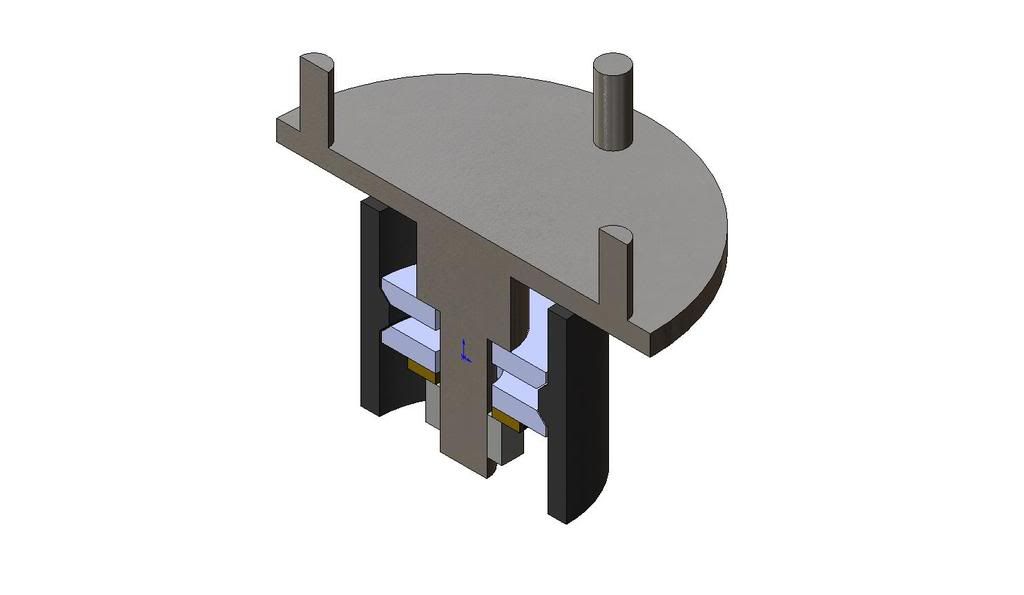
This picture show the typical setup of a Locost.

After several evaluations we did decided to go in a different way, the Sierra hub don't give us the parameters that we want to have. The
mushroom piece should be changed in such way that would be result in a bad design.
But is our opinion, and we are quit stringent with our suspension design.
Regards,
Cobra289
https://forocoches.com/foro/showthread.php?t=1699619
|
|
|
Cobra289
|
| posted on 17/8/08 at 12:44 PM |
|
|
quote:
Originally posted by hellbent345
i need to know how the stub axle passes through the bearing and is held on? thanks
alan
I found a exploded view at the Ford manual where you can see the components used at the front upright.

I hope that this help you.
Regards,
Cobra289
[Edited on 17/8/08 by Cobra289]
https://forocoches.com/foro/showthread.php?t=1699619
|
|
|
Syd Bridge
|
| posted on 18/8/08 at 09:38 AM |
|
|
That SW dwg is far from correct. I've got a copy of the original Ford dwgs somewhere, I'll try and find them, but I know from dealings
with the original design team, the upright was always intended to be front steer, and front wheel drive. It just didn't end up that way.
I'd be very wary of turning the hubs around and rear steering the system, as well. I've seen it done, and the awful consequences.
The axle is held in with a big nut under the cover plate, sandwiching the bearings, which have a ridge between them in the main knuckle casting.
And again, these are made from SG IRON, NOT forged or cast steel.
Cheers,
Syd.
|
|
|
Cobra289
|
| posted on 18/8/08 at 10:02 AM |
|
|
quote:
Originally posted by Syd Bridge
That SW dwg is far from correct. I've got a copy of the original Ford dwgs somewhere, I'll try and find them, but I know from dealings
with the original design team, the upright was always intended to be front steer, and front wheel drive. It just didn't end up that way.
I'd be very wary of turning the hubs around and rear steering the system, as well. I've seen it done, and the awful consequences.
The axle is held in with a big nut under the cover plate, sandwiching the bearings, which have a ridge between them in the main knuckle casting.
And again, these are made from SG IRON, NOT forged or cast steel.
Cheers,
Syd.
Hi Syd,
It would be nice to have the Ford drawing, because make the part in SW is not a big deal, the problem is just find the right information.
As I did mention, my model is based on the posted drawing [link above]
Thank for the inside information it is always interesting to know.
Regards,
Cobra289
[Edited on 18/8/08 by Cobra289]
https://forocoches.com/foro/showthread.php?t=1699619
|
|
|
Liam
|
| posted on 18/8/08 at 06:18 PM |
|
|
On my Sierra 4x4 uprights the bottom and top balljoints are perfectly aligned. Are you sure that built in negative castor really exists? I
can't see why they'd do it that way as the production car is McPherson strut and the caster is determined by the rearward inclination of
the whole upright/strut assembly. Anybody got a real one to look at?
Liam
|
|
|
Cobra289
|
| posted on 18/8/08 at 06:49 PM |
|
|
quote:
Originally posted by Liam
On my Sierra 4x4 uprights the bottom and top balljoints are perfectly aligned. Are you sure that built in negative castor really exists? I
can't see why they'd do it that way as the production car is McPherson strut and the caster is determined by the rearward inclination of
the whole upright/strut assembly. Anybody got a real one to look at?
Liam
Liam,
I am not shore about it.
This is the drawing that I got to make it.
http://www.locostbuilders.co.uk/viewthread.php?tid=90788
It looks pretty convincent. I did ask, for the drawing, because don't have access to the real upright.
Regards,
Cobra289
https://forocoches.com/foro/showthread.php?t=1699619
|
|
|
hellbent345
|
| posted on 20/8/08 at 08:29 AM |
|
|
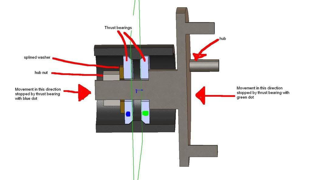
so by the looks of that drg, the hub is kept from falling out by 2 thrust bearings, clamped onto an inner surface of the upright? the inside one
stopping it from falling outwards, the outer one stopping it from sliding inwards? ill draw a pic lol
also im not planning to turn them round, im planning to use rortys many posts to help design a new upright with good geometry and rear steer.. if i
can get it in the space available!
quick rough idea of what i recon the inside on an upright is like from the above comments and drgs, is it right? someone correct me if not
[Edited on 20/8/08 by hellbent345]
|
|
|
Cobra289
|
| posted on 20/8/08 at 10:40 AM |
|
|
quote:
Originally posted by hellbent345
so by the looks of that drg, the hub is kept from falling out by 2 thrust bearings, clamped onto an inner surface of the upright? the inside one
stopping it from falling outwards, the outer one stopping it from sliding inwards? ill draw a pic lol
also im not planning to turn them round, im planning to use rortys many posts to help design a new upright with good geometry and rear steer.. if i
can get it in the space available!
quick rough idea of what i recon the inside on an upright is like from the above comments and drgs, is it right? someone correct me if not
[Edited on 20/8/08 by hellbent345]
Besides of the proportion the drawing is OK.
The bearings are taper type.
The lip at the bearing carrier is bigger.
If you plant to make a upright using the Ford design, keep the dimension exactly like the Ford ones, because that will guaranty that you have a
correct bearing end-play.
You have U2U.
Regards,
Cobra289
https://forocoches.com/foro/showthread.php?t=1699619
|
|
|