flak monkey
|
 posted on 2/4/06 at 06:05 PM posted on 2/4/06 at 06:05 PM |

|
|
Engine Sorted (quite a lot of pics)
Finally things are coming along nicely
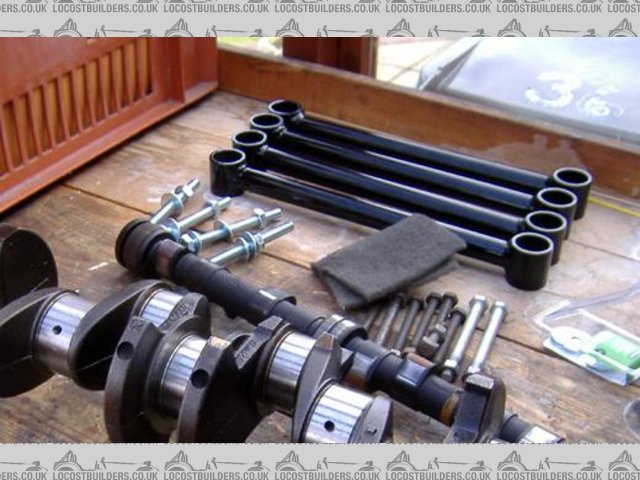
Picked my engine up just over a week ago from Brian (BKLOCO) and I have spent the last week getting it ready to be reassembled. All of the parts that
are needed are on order and will arrive this week (unfortunately I am back at uni now though!)
First the bores were measured, and the wear found to be well within the acceptable limits, so no rebore is needed just yet.
The block and head were cleaned and de-rusted with the help of the tool (angle grinder with wire brush attachment). The pis shows the block partially
cleaned.

Then the bores were deglazed to help the new piston rings to bed in.
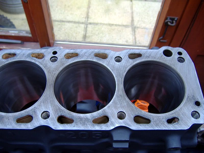
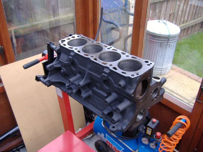
The block was then painted with hi-temp paint and looks quite good if i do say so myself. 
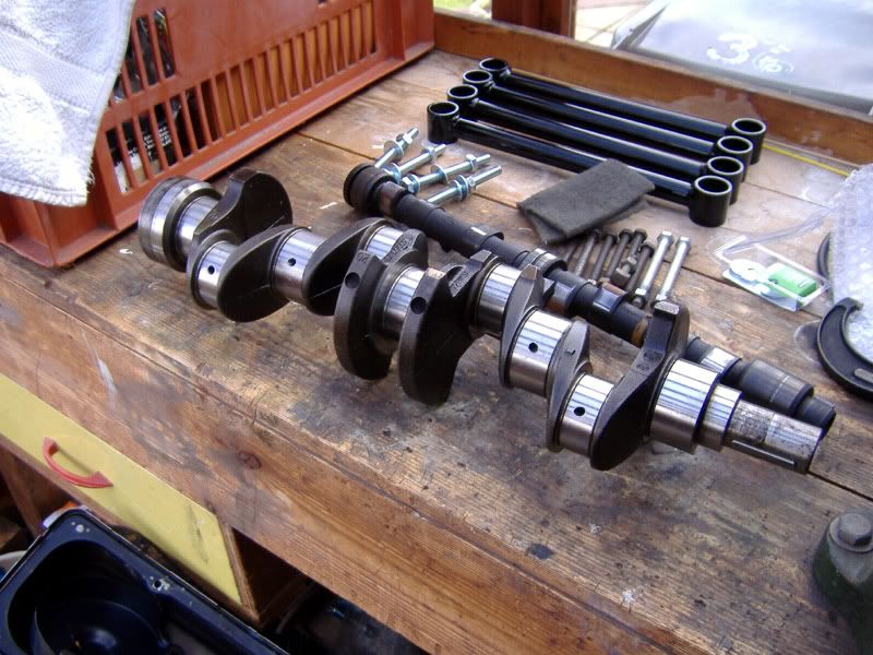
The crank journals were polished and then measured and found to show no wear on the main journals and 0.005mm ovality on big end journals. Well within
limits.
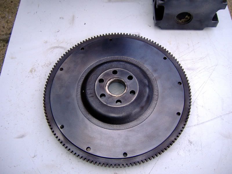
The lightened flywheel was cleaned up as it had some surface rust
The head isnt unleaded unfortunately, but the valve seats arent too bad, and just need to be reground which I started but didnt finish before I came
away. The plan is to run on additive until recession is serious and then have the head converted (I spent the best part of a week trying to track down
an unleaded head, but to no avail!)
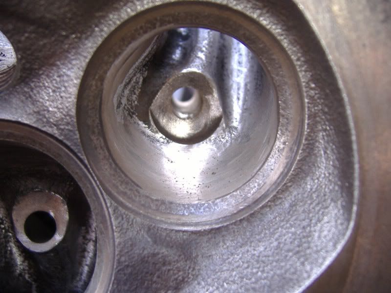
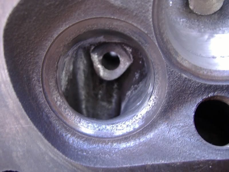
I have modified the valve throats quite heavily. Radiusing the inlet short turn and opening the port out as far as possible without interfering with
the valve seat. The port itself has only had the worst of the casting roughness removed, but has been left unpolished to avoid problems with fuel
condensing on the walls.
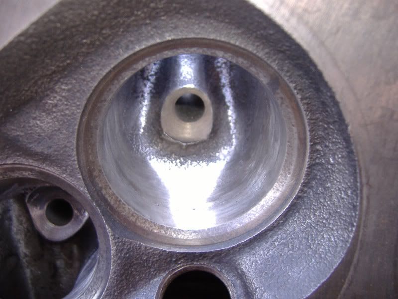
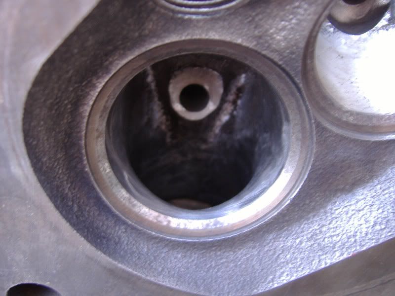
The exhaust port throat has also had some modification. With the casting steps removed completely from the throat (see pics) and the short turn well
radiused as well. The port itself has been cleaned up as well so it is completely smooth.
Hopefully the head modifications will see some decent power gains. They didnt take long anyway.
Any comments?
David
Sera
http://www.motosera.com
|
|
|
|
|
donut
|
| posted on 2/4/06 at 06:10 PM |
|
|
Lookin good my man! There is something really nice about a freshly built engine.
Andy
When I die, I want to go peacefully like my Grandfather did, in his sleep -- not screaming, like the passengers in his car.
http://www.flickr.com/photos/andywest1/
|
|
|
I love speed :-P
|
| posted on 2/4/06 at 06:14 PM |
|
|
nice
Don't Steal
The Government doesnt like the competition
|
|
|
Hellfire
|
| posted on 2/4/06 at 06:23 PM |
|
|
It looks a bit heavy 

|
|
|
Surrey Dave
|
| posted on 2/4/06 at 06:26 PM |
|
|
I'm not quite sure if i'm seeing it right but the valve seats look very pitted or else it is a wide piece of the casting which could be
shaped out o the valve seat to help the flow go past the edge of the valve.
The area inside the combustion chamber that recesses the valve can be removed /smoothed out to reduce shrouding at the smaller valve openings.
|
|
|
birt
|
| posted on 2/4/06 at 06:36 PM |
|
|
The valve seats do look pitted and will require a real good lapping-in. I have turned seats like this into a mirror finish before but it takes some
time and sweat. You'll need to start with a course paste.
|
|
|
britishtrident
|
| posted on 2/4/06 at 06:50 PM |
|
|
Valve seats could do with being re-cut with a 3 angle cutter.
As for valve lapping depends on the valves you fit the original Ford inlet valves and some replacements are coated not supposed to be lapped in. When
lapping in valves aim for a perfect fine matt finish.
|
|
|
zilspeed
|
| posted on 2/4/06 at 07:07 PM |
|
|
Don't think much of your conrods either...
[Edited on 2/4/06 by zilspeed]
Rescued attachment Rods.JPG
|
|
|
flak monkey
|
| posted on 2/4/06 at 07:12 PM |
|
|
Yes those pics were taken before the valve seats have had any treatment. I have lapped a couple of them in, but havent done them all yet! All of the
steps inside the thoats have been removed.
Further mods planned include unshrouding the valves. I didnt have time to do all the work I wanted to do in a week, what with uni work to do as
well.
Hellfire: How did I know you would make a comment like that?
Zil:
Sera
http://www.motosera.com
|
|
|
SixedUp
|
| posted on 2/4/06 at 07:30 PM |
|
|
quote:
Originally posted by Hellfire
It looks a bit heavy
That's not weight. That's muscle
Cheers
Richard
|
|
|
BKLOCO
|
| posted on 3/4/06 at 10:57 AM |
|
|
That's looking too good.
I clearly didn't charge you enough
Experience is what you get when you don't get what you want!!! 
|
|
|
tks
|
| posted on 5/4/06 at 01:20 PM |
|
|
Mhhh
The inlet and outlet ports are very very important of the complete suction performance (effeciency) of the engine.
Be sure to do it the right way!
for example: an inlet port wich has little risistance has it also the way out...
that means that any air in the engine can also easy go out..
same for the outlet port..
if you make it to icey..you could lose mixture during the valve overlapping.
Sow the trick would be for you the right CAM..
regards,
Tks
The above comments are always meant to be from the above persons perspective.
|
|
|
flak monkey
|
| posted on 5/4/06 at 02:41 PM |
|
|
The head work has been carried out in accordance with that detailed in the Des Hamil Pinto tuning book, based on using std size valves.
Exhaust ports can be polished. Inlet ports shouldnt be. The idea is to provide the least resistance to the exiting exhaust gases so they leave as
quickly as possible. A similar idea would apply to the inlet port but as the inlet charge is a mixture of air and liquid, polished surfaces result in
the fuel condensing on the port walls and not being carried to the cylinder. So on the inlet side the port just has to be smoothed and all edges
removed, but not mirror polished.
The valve overlap occurs as the exhaust gases leave and the inlet charge enters. The vacuum left by the exhaust gases rushing out helps the inlet
charge be drawn in.
There is no way you can lose inlet charge back up the inlet port.
Some of the inlet charge can be lost through the exhaust port if the cam has too much overlap. But all useable cams for the road dont have enough
overlap for this to be a major problem.
Cheers,
David
[Edited on 5/4/06 by flak monkey]
Sera
http://www.motosera.com
|
|
|
MikeRJ
|
| posted on 6/4/06 at 09:57 PM |
|
|
quote:
Originally posted by flak monkey
There is no way you can lose inlet charge back up the inlet port.
There certainly is with long duration cams. It's called reversion, and leads to really bad stand- off where fuel hangs around the open end of
the carb/throttle body.
|
|
|
tks
|
| posted on 7/4/06 at 11:23 AM |
|
|
:D
To maximize your air effiicency..
the trick is to suck in the engine and bring the hole air stream in the manifold up to speed...
once on speed if you let the port more time open more will flow in..
but as we all now there is the dead point
LDP and if the inlet port stays open 1 degree after this point (when you have high open duration cams) then you are expanding and loosing the mixture
trough the inlet port.
But for very very high reving engines the air speed is high enough to block that pair of degree and still be usefull and the stream will still be
pushin in.
altough the idle will be sucks, air will be blown oud hence low speed!
look at F1 engines they have the same problem/trick.... (in fact they don´t have butterflies but ok)..
They do everything with the cam, and adjust the lift as accelerator..
more lift more air more power.
in fact the butterfly just reduces power..
(they are like the old air quantity meters of LJETRONIC, dump it and you have got 15BHP more..)
in fact we needed an one way valve on the inlet port but offcourse becuase of its nature its restrictive..
now you know wy an f1 engine has an idle of min. 3500rpm..
also another thing is that the hole CAM idea is sucks because its the most BHP consuming thing on the hole engine...
you need to accelerate the cam, to brake it, in F1 they don´t have a CAM here they again win allot of BHP.
[Edited on 7/4/06 by tks]
The above comments are always meant to be from the above persons perspective.
|
|
|
NS Dev
|
| posted on 11/4/06 at 03:16 PM |
|
|
Main thing with a pinto inlet port (never read the hammill book but I'm guessing he'll put it this way) is to get the inlet flow to run
across the back of the inlet valve, rather than turn down run vertically down it, if you see what I mean.
The main things stopping this normally are the short side turn, which pulls the mixture around the corner instead of letting it flow to the far side
of the valve, the guide boss, which helps initiate the turn that you don't want the air to make to start with, and the back of the valve itself,
which is too fat and gets in the way of the air trying to flow across it, hence again making it turn instead of go straight on.
The key with the pinto is forget opening the ports up, they are huge already.
1) Reprofile the backs of the inlet valves as flat as you dare without the heads falling off (as to how far that is, your guess is as good as mine!)
You have access to a lathe and a die grinder, stick the valve in the lathe and redo the back with the grinder with the lathe bed covered up with a
blanket so you don't get shot!
2) cut the guide bosses back, by about 1/2 their length if keeping the cast iron guide, or completely if using bronze guides (strongly recommended and
not exxypensive to do)
3) try to straighten the port out without making it bigger.....ha ha very funny you will say as that is flipping impossible, yep, but you can take off
some of the short side turn, and some on the valve throat area the opposite side, and a tad on the port roof at the start of the port, blend it all in
and it will make a big difference to flow when used with a flat back valve.
there you go!
Retro RWD is the way forward...........automotive fabrication, car restoration, sheetmetal work, engine conversion
retro car restoration and tuning
|
|
|
NS Dev
|
| posted on 11/4/06 at 03:23 PM |
|
|
quote:
Originally posted by tks
you need to accelerate the cam, to brake it, in F1 they don´t have a CAM here they again win allot of BHP.
[Edited on 7/4/06 by tks]
ehhh???????????
As far as I know F1 engines have cams just like any other engine, unless technology has passed me by!!
Yes they have "pneumatic valve technology" this is gas springs for the valves, which enables the use of variable rate valve springs,
giving low seat pressures at low revs and increasing seat pressure with revs to prevent resonance, but the valves are still opened and shut by a good
old camshaft unless things have changed in the last 2 years?
Retro RWD is the way forward...........automotive fabrication, car restoration, sheetmetal work, engine conversion
retro car restoration and tuning
|
|
|
flak monkey
|
| posted on 11/4/06 at 03:30 PM |
|
|
Thanks for that Nat
I am not planning on opening the ports up, the Hamill book says they are huge, and they do look big compared to other engines I have seen.
The short turn has been modified as suggested in most of the tuning books. I have radiused it as much as possible, and tried to flatten the turn as
well.
As for the guide bosses, they are standard at the moment, as you can see. I was concerned about them posiibly cracking if thinned down, or cut back
too much. Or is this not a problem?? I am not fitting new guides yet, as the standard ones are in perfect condition at the moment.
I might have a go at re-profiling the backs of the valves. But dont really want them falling apart, since they are the standard 2 piece friction
welded jobbies..!
Sera
http://www.motosera.com
|
|
|
NS Dev
|
| posted on 11/4/06 at 03:35 PM |
|
|
sorry couldn't see the pics at work they get blocked!
If you wanto to save money and get on the road quick then you can always build up a spare head later and swap over.
If you're not bronze guiding it then just reduce the guide/guide boss a bit and smooth it off. You will be safe to "do a bit" on the
valve backs but not too much, can't really say how much as I've always worked by gut feel, plus the last few I've done were opel CIH
ones not Pinto (similar though!)
cheers
Nat
Retro RWD is the way forward...........automotive fabrication, car restoration, sheetmetal work, engine conversion
retro car restoration and tuning
|
|
|
tks
|
| posted on 11/4/06 at 08:02 PM |
|
|
F1 Engines
As far as i'm aware of the F1 engines of today don't have an ordinary camshaft....
It has changed allot, they don't have the butterfly (as throtle) instead of that they adjust the valve lift...
When they program a higher valve lift at given rpm / map etc..
I think that you can say they don't have the ordinary cam shaft like we know them.
Thats what i want to say! also they don't have the valve springs. (they went out many many years ago 6+, they broke etc. when passing the
18.000rpm limit it was Renault who invented them.
Since then its all pneumatic, i'm sure they will have some kind of camshaft wich will give the signals to the pneumatic pistons.
but the ordinary BHP eating spring camshaft isn't there anymore that for sure!!
anyway in making it from berriliuym they do reduce weight and increase bhp...
Hope i'm not totally wrong we shall see
if htere is a F1 mecanien on the site..
Tks
The above comments are always meant to be from the above persons perspective.
|
|
|
C10CoryM
|
| posted on 17/4/06 at 04:11 PM |
|
|
No one in F1 has claimed to be running a camless engine yet. Cam opened/air closed is still the common way of doing it. There are rumours of Renault
running a camless engine this year though. They have been playing with hydraulic opened valves recently. It is not far away from being common in F1.
Large diesel engines and a few automotive engines run without cams.
Cheers.
"Our watchword evermore shall be: The Maple Leaf Forever!"
|
|
|


.jpg)