kb58
|
| posted on 23/4/10 at 03:04 PM |

|
|
quote:
Originally posted by TheGecko
... Standing looking at the caster, getting measurements, SWMBO enters workshop and sees me in flip-flops(*note) - says "Are you putting your
safety boots on?". "Yes dear, once I actually start working on things". Put castor down, only to have it overbalance, and fall from
bench height onto big toe nail  . .
Reminds me of the line from the movie, The Matrix: "Don't worry about the vase." If she hadn't said anything...
Mid-engine Locost - http://www.midlana.com
And the book - http://www.lulu.com/shop/kurt-bilinski/midlana/paperback/product-21330662.html
Kimini - a tube-frame, carbon shell, Honda Prelude VTEC mid-engine Mini: http://www.kimini.com
And its book -
http://www.lulu.com/shop/kurt-bilinski/kimini-how-to-design-and-build-a-mid-engine-sports-car-from-scratch/paperback/product-4858803.html
|
|
|
|
|
TheGecko
|
| posted on 11/5/10 at 01:09 PM |
|
|
Suspension work continues apace.
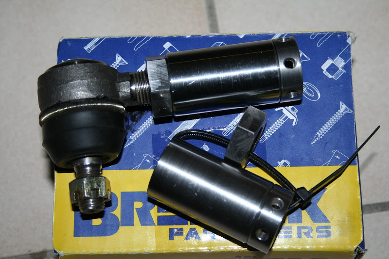
On the weekend my machinist friend handed me a box with my top wishbone threaded bushes - these are the "infinite adjustment" type with a
threaded sleeve inside the weld tube - see photo. No excuses not to get my wishbones finished now  Thanks again Paul. Thanks again Paul.
The rear end of the car is strut by Corolla uprights and modified strut tubes. The Corolla bottom balljoint is an odd shape (a little reminiscent of
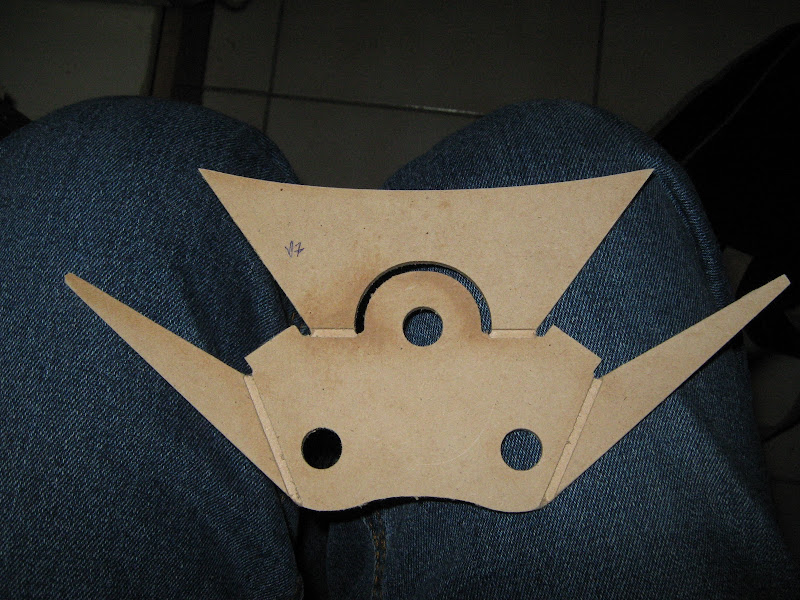
the angled Cortina lower part) and I'd spent a bit of time fussing around how I'd mount it. Last night I picked up this from my engraver
friend:
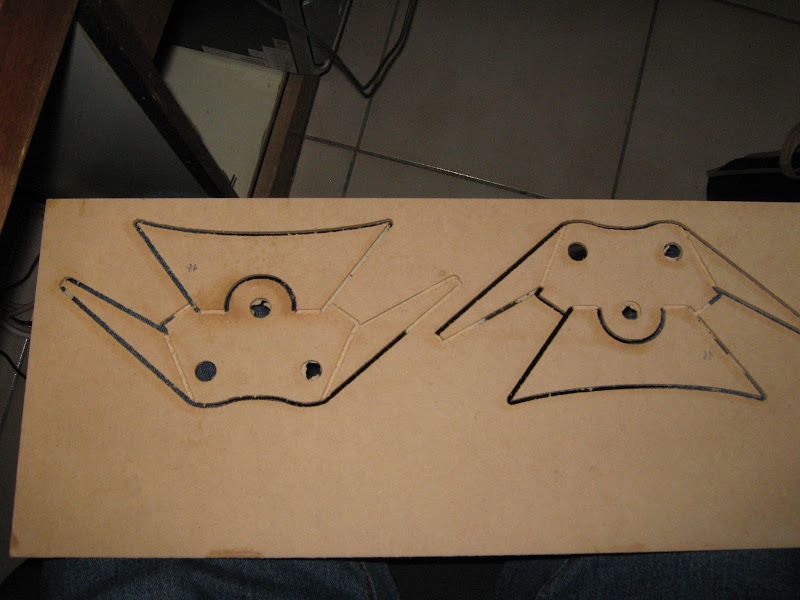
Two sample wishbone plates, test cut in 3mm MDF. Once knocked out and cleaned you get this. Note the half depth slots - these are to encourage and
assist some bends.
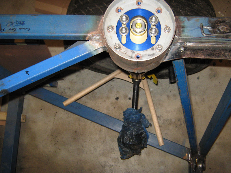
Once bent and hot-glued to some 22mm dowel "wishbone tubes" you get this:
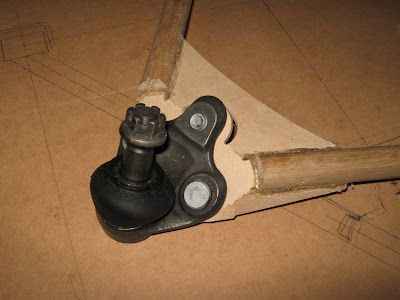 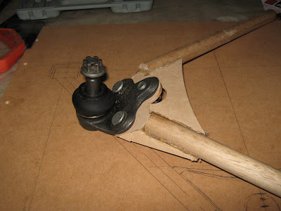
And here's the mock-up wishbone in place with the upright etc to check clearances:
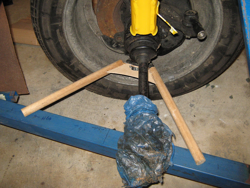
There's a few small tweaks needed but it looks like I can get the real deal cut in 3mm steel sometime early next week. Should be able to tack
up top front and rear wishbones all at once 
Dominic
|
|
|
cheapracer
|
| posted on 23/5/10 at 01:47 PM |
|
|
Dom you understand if you run your exhaust too close to those wooden arms that they will catch on fire?
Not that thats a problem but the fire will surely melt that very thin plastic CV boot THEN you will be in the shit.
|
|
|
TheGecko
|
| posted on 24/5/10 at 09:38 PM |
|
|
Thanks for that advice Mark. It's this sort of insightful, helpful advice that keeps me coming back here 
Dominic
|
|
|
Benonymous
|
| posted on 8/6/10 at 07:24 AM |
|
|
What about when it rains????
MDF just swells up and disintegrates!!
If you'll take my sage advice, you'll switch to oak for those components or spruce if you desire light weight.
|
|
|
ceebmoj
|
| posted on 9/6/10 at 08:23 AM |
|
|
why did wooden cars fall out of favour? the early marcos where wood construction and im sure there where others.
|
|
|
iank
|
| posted on 9/6/10 at 08:33 AM |
|
|
quote:
Originally posted by ceebmoj
why did wooden cars fall out of favour? the early marcos where wood construction and im sure there where others.
Morgan still have an ash frame supporting the body.
I think the workmanship and time required for a wood frame is a lot more than that required to mig together some tube.
--
Never argue with an idiot. They drag you down to their level, then beat you with experience.
Anonymous
|
|
|
TheGecko
|
| posted on 9/6/10 at 10:39 PM |
|
|
I'm hoping that everyone is just gently taking the p*ss here. However, just to re-iterate and to avoid any misconceptions - these are purely
mock-up parts made to check the fold angles of the ball-joint plate etc.
The finished product will be made of steel.
Dominic
|
|
|
rick q
|
| posted on 10/6/10 at 03:27 AM |
|
|
quote:
The finished product will be made of steel.
Risky choice Dominic - steel rusts.
A few decent coats of quality spar varnish on the MDF will make it a much better choice than steel!
|
|
|
TheGecko
|
| posted on 18/3/11 at 01:46 PM |
|
|
Following some nudges by another member here (Hi John), I'll add a quick status update.
Front wishbones are done (top and bottom)

I made a two-part jig to align the wishbone brackets to the chassis (double sided so I use it for left and right)
The bottom part can slide fore and aft along the chassis for one part of the alignment while the top half slides in and out to offer up the brackets
to the chassis. And here's a picture of the brackets ready for tacking.
Because the shape of my car isn't really like a Locost in terms of angles etc, there's no easy way to make a "standard"
nosecone fit. I got a spare fibreglass nosecone from a mate and looked at splitting and re-joining it but couldn't see it turning out well.
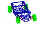
Inspired by John's (member 2cv) posts on metal shaping (see more in this
thread), I've decided to have a crack at making one in aluminium. Here's the quick Sketchup model I drew quite a while ago to get
a sense of the basic shape, which is almost all single curvature.

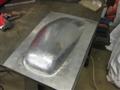
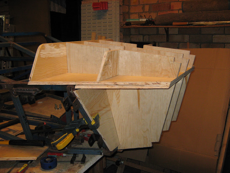
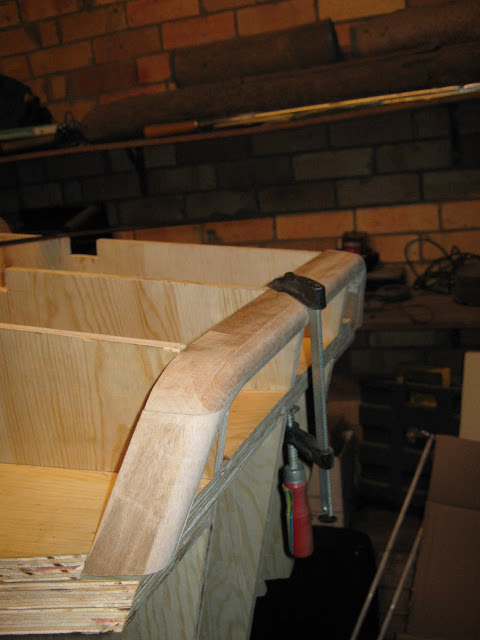
And here's the current state (pretty much) of the buck I'm building to form the nosecone over.
I've got 4-weeks of leave coming up soon (in three weeks today actually!) to work on the car - SWMBO is only off work for the last 4 days of it.
The intent, by the end of that time, is to get the car to:
- chassis fully welded, including all brackets etc (95% done already anyway)
- suspension all fitted and car on the ground on its wheels (front is mostly done - rear remains to complete)
- all major fixed panels fitted (i.e. firewall, floor pan, sides etc)
- brakes & clutch plumbed
- chassis structural tests completed (required for registration here - full torsion & beam strength tests)
- engine mounted and plumbed (but probably not wired - dealing with the horrifying loom may need 4 weeks all on it's own!)
Expect some more updates soon.
Dominic
|
|
|
cheapracer
|
| posted on 22/3/11 at 12:45 PM |
|
|
Dominic, will you be using a resin or lacquer to protect the wood from the elements?
Sump oil, although harder to clean bugs off and a bit smelly, would be locost.
It's coming....
|
|
|
TheGecko
|
| posted on 23/3/11 at 07:00 AM |
|
|
quote:
Originally posted by cheapracer
Dominic, will you be using a resin or lacquer to protect the wood from the elements?
Sump oil, although harder to clean bugs off and a bit smelly, would be locost.
I was going to go "old school" actually and use left-over house-paint. I've got a half-tin of "Hazel Mist" semi-gloss
acrylic that should look quite nice.
As always, thanks for your helpful and constructive input
Dominic
|
|
|
2cv
|
| posted on 23/3/11 at 08:38 AM |
|
|
Thanks for the update Dominic, excellent work. I'm looking forward to seeing pics of the next bit. Do hope you enjoy your break from work and
that you can get on with the important stuff!!
John
|
|
|
TheGecko
|
| posted on 23/3/11 at 01:15 PM |
|
|
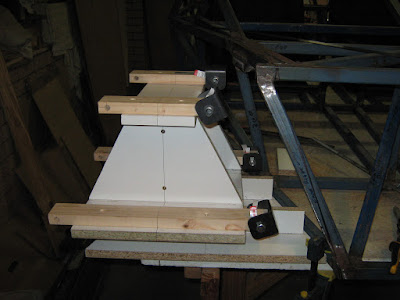
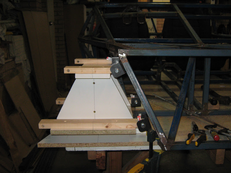
Small update since I actually got home early enough to get into the workshop (for a little while at least).
First part of the nose profile piece for the nosecone buck. Photo 1 is before running across the router table to put inside and outside radii on it
(6.35mm and 12.7mm respectively). Photo 2 is after (duh!).

Still need to finish some of the intermediate braces in the buck (it needs to strong if I'm intending to hammer on it at all!) and make the
bottom part of the profile.
2-and-a-bit weeks till I'm on leave. Lots of things to get organised before then
Dominic
|
|
|
cheapracer
|
 posted on 30/3/11 at 06:19 PM posted on 30/3/11 at 06:19 PM |
|
|
quote:
Originally posted by TheGecko
As always, thanks for your helpful and constructive input
Dominic
he he - take the bit of fun as a compliment, not much to criticize on your build, well done!
It's coming....
|
|
|
TheGecko
|
| posted on 5/4/11 at 11:48 AM |
|
|
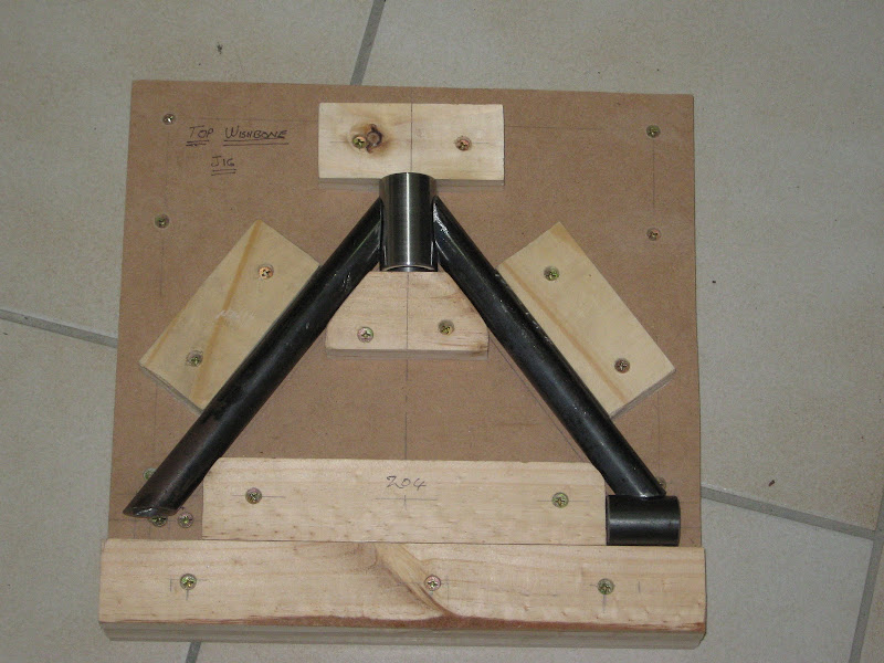
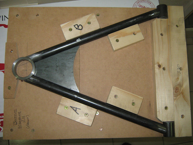
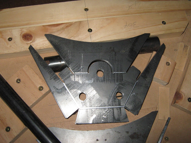
Some updates - got to a final design for the rear wishbone balljoint plates. Here they are CNC cut with slight grooves to assist vise bending; and
one folded and bolted into the wishbone jig.
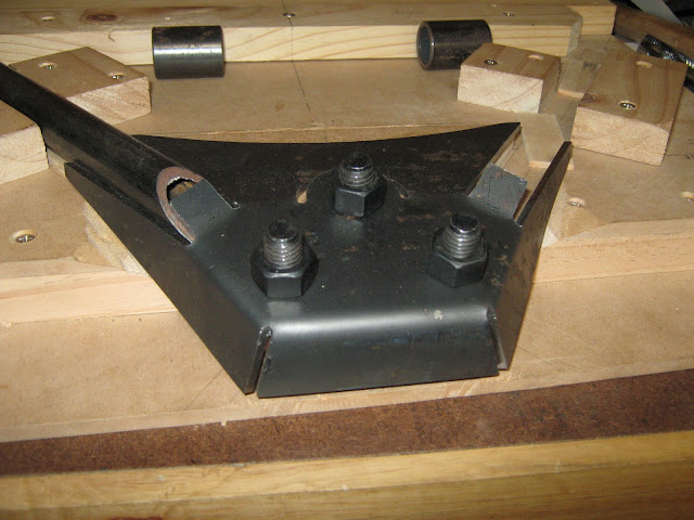
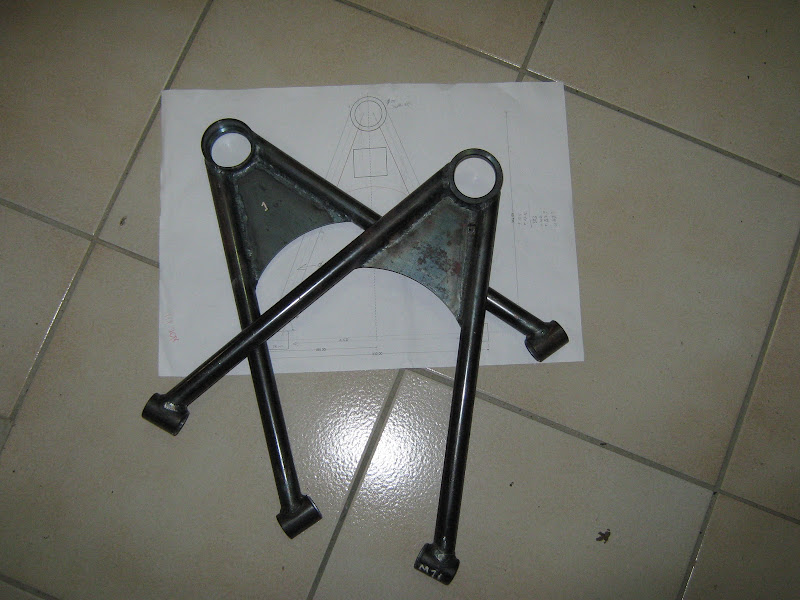
Final product all TIG welded then painted; showing the underside of the folded part; and with the ball joint mounted.
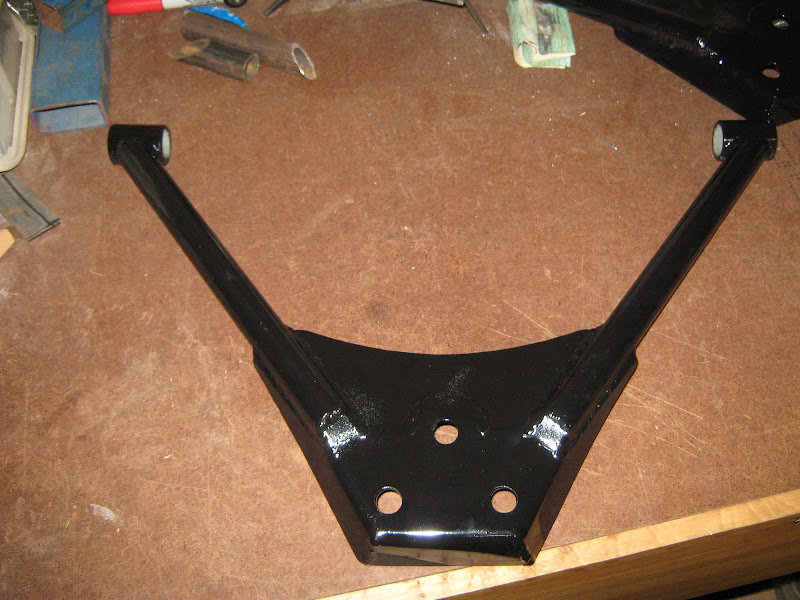
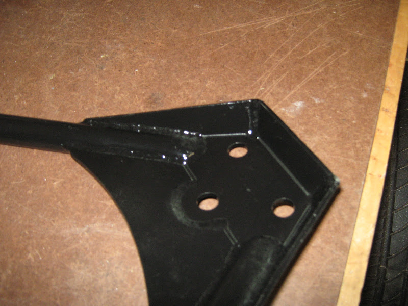
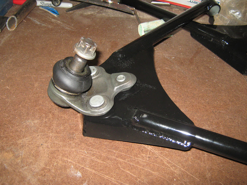
Holidays start this weekend - lots to do!! More updates soon.
Dominic
|
|
|
SeaBass
|
| posted on 5/4/11 at 12:11 PM |
|
|
Wont' your lower wishbone be almost parrallel to the ground? If so that bottom ball joint will be at a really odd angle to the upright? The
balljoint stub wouldn't be central and therefore risk binding? What thickness is that plate?
[Edited on 5/4/11 by SeaBass]
|
|
|
TheGecko
|
| posted on 5/4/11 at 12:18 PM |
|
|
All good questions SeaBass
The wishbone will actually be downhill to the ball joint at normal ride height, because the rail the brackets are going on puts the pivots about 200mm
above ground level.
The balljoint is at an odd angle but that's because the hole in the upright is too - it points at the top of the strut, not vertically. Found
that out the hard way when the original plate design put the balljoint shaft vertical and then realised they would've run out of motion in droop

The plate is 3.5mm-ish - I suspect it's actually badly toleranced 1/8". I got a 600x1200 sheet of it for a few dollars scrap value and
it's served me well for all of my various brackets.
Dominic
[Edited on 5/4/2011 by TheGecko]
|
|
|
2cv
|
| posted on 12/4/11 at 06:29 AM |
|
|
There's some really nice work gone into those wishbones Dominic; very impressive, neat folding on what is quite thick material. I particularly
like the little tabs that act as tube stops. Keep the pictures coming please.
[Edited on 12/4/11 by 2cv]
|
|
|
TheGecko
|
| posted on 12/4/11 at 07:20 AM |
|
|
Thanks John, I'm very happy with how the wishbones turned out. The steel was surprisingly easy to bend because the portions being bent were
relatively small and the rest of the plate gave me leverage. Plus, the very shallow (~0.5mm) slots "encouraged" a bend in the correct
place. Given the amount of metal and the final welded form I'm not worried about any lost strength from those slots.
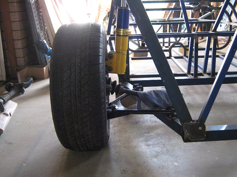
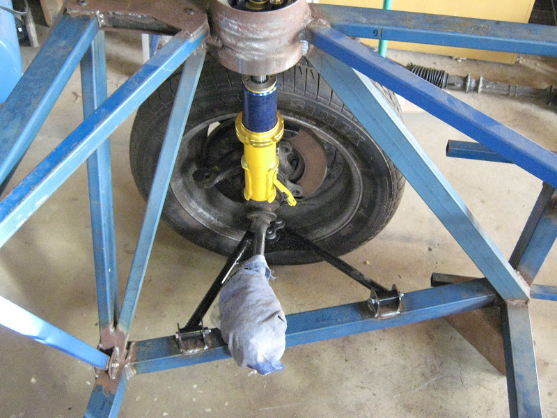
Just catching my breath the last few days after finally starting my leave so not much to show yet. However, I did bolt together one whole set of rear
suspension with the wishbone brackets clamped on the chassis to check. Very pleased to measure static camber at about 1 degree negative, with some
range in the strut adjustment to go further. That's what all of the design work said it should be but reality has a way of proving me
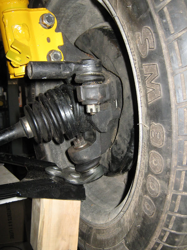
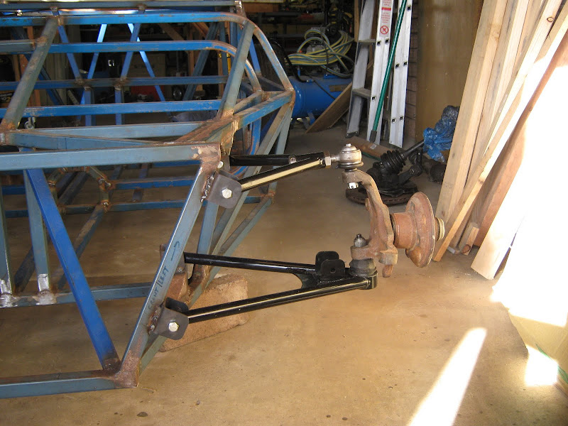
wrong sometimes Pic of the whole assembly below, plus another showing the inclined entry angle in the Corolla upright, explaining the
"odd" angle of the ball joint and wishbone.

Sometime in the next day or two I'll get the wishbone brackets welded to the chassis. Then I can drop the whole thing down on the floor and see
what I've got Next thing after that will be toe-links using the original tie-rod end as the outer (visible in the pics) and a spherical
joint as the inner end.
More updates as they happen....
Dominic
|
|
|
2cv
|
| posted on 12/4/11 at 11:14 AM |
|
|
It's very satisfying when theory and practice agree and the great plan comes together. It really is looking very good; you must be delighted
with what you've achieved. Only another builder can appreciate the painstaking work that has gone into this build. Quality in every joint!
atb
John
|
|
|
TheGecko
|
| posted on 14/4/11 at 09:16 AM |
|
|
Thanks for the kind remarks John.
A bit of progress today as a friend came round to help and managed to nudge me through my normal rounds of "Paralysis by Analysis" End
result - rear suspension brackets aligned and fully welded.
Plus, he helped me flip the chassis over so I could finish some of the underside welds. After they were done, I flipped it back and dragged it off the
build table and stuck some front suspension on too
Don't look too closely at the welding on those brackets. Need grinding out and redoing with the chassis at a more workable angle
More updates as they happen....
Dominic
|
|
|
TheGecko
|
| posted on 5/1/12 at 03:26 PM |
|
|
Well, in the pursuit of some progress, the chassis has moved to a friend's workshop where I have access to better tools but more importantly his
much better expertise which will hopefully nip any "analysis paralysis" issues in the bud. There's plenty going on in his shop
already - and there's another car behind were I was standing too!

D
|
|
|
rowlocks
|
| posted on 13/1/12 at 11:20 PM |
|
|
Hi,
Awesome project! Just a question about your rear suspension,
What shocks are you using? Are they designed to be used for macpherson struts? A macpherson strut would place greater side loads on the shock wouldnt
it? Also will you have a handbrake?
|
|
|
TheGecko
|
| posted on 14/1/12 at 11:48 AM |
|
|
Hi rowlocks,
The strut inserts I'm using are specific parts for Macpherson struts, not some generic shock absorber. You can see one of them in my post from
21 Jul 2008. Note how thick the shaft is compared to a normal shock? That's to deal with side loads.
Handbrake - I'm using Corolla AE101 front uprights and discs but replacing the calipers with XF Falcon rears which are: the right width, have a
handbrake mechanism, and are alloy so quite light.
Hope this helps,
Dominic
|
|
|