kango
|
| posted on 11/7/08 at 08:09 AM |

|
|
Making an adaptor plate - process
Lets hear from the people that has done it and perfected it.
What would the PROCESS be to make an accurate adaptor plate between the bell housing and the engine if you do not have any drawings of the engine or
bell housing bolt patern? 
|
|
|
|
|
Fred W B
|
| posted on 11/7/08 at 08:15 AM |
|
|
Hay Kango
If you pop in at mine tomorrow arvo I can talk you through what I did.
Cheers
Fred
You can do it quickly. You can do it cheap. You can do it right. Pick any two.
|
|
|
mr henderson
|
| posted on 11/7/08 at 08:17 AM |
|
|
quote:
Originally posted by kango
Lets hear from the people that has done it and perfected it.
What would the PROCESS be to make an accurate adaptor plate between the bell housing and the engine if you do not have any drawings of the engine or
bell housing bolt patern?
Me too, I would be very interested in that.
I assume it would start with findng a way of lining up the input shaft of the gearbox with the crankshaft of the engine, while sandwiching a piece of
aluminium between the two (with a hole in it to allow the inout shaft to pass through.
Then scribing the outline of the bolt holes into each side of the plate?
John
|
|
|
kango
|
| posted on 11/7/08 at 08:27 AM |
|
|
I have herd a couple of ways of how to do it.
Making half the thickness plate for the one part and half the thickness for the other side. Then line the whole lot up , clamp it and weld the 2
plates together.
What happens to the dowls?
There is nothing on this site and thought it might get a conversation going between some experts and leave everybody with what they think is the best
and the easiest.
|
|
|
nludkin
|
| posted on 11/7/08 at 09:05 AM |
|
|
This guy has a nice gallery of how he accomplished it.. Linky
|
|
|
kango
|
| posted on 11/7/08 at 10:58 AM |
|
|
Different idea - using the washers as his final allignment adjustment.
|
|
|
nasty-bob
|
| posted on 11/7/08 at 01:54 PM |
|
|
If you have the dimensions of the bolt pattern then the adapter itself is pretty straight forward. I drew mine up in CAD after having the engine and
bellhousing CMM'd. I then had the plate (20mm ally) with all the bolt holes (undersize) waterjet cut.
Holes then drilled and tapped as necessary. Some of the bolts into the engine that got in the way of bellhousing had to be countersunk.
The more difficult bit is going to be the flywheel which I'm going to have to design myself when I get a chance.
Cheers
Rob
 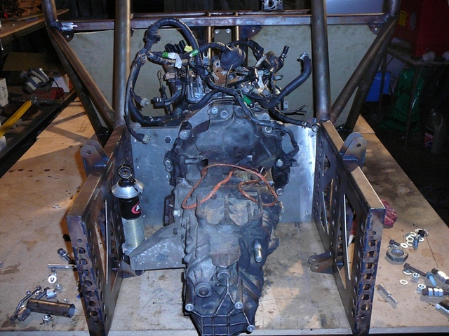
Rescued attachment P1000179-1.JPG
|
|
|
kango
|
| posted on 11/7/08 at 02:46 PM |
|
|
I have asked if anybody has the bolt patern on the bell housing to engine of a Type 9.....still waiting...that is whis post was my second option.
|
|
|
D Beddows
|
| posted on 11/7/08 at 03:38 PM |
|
|
quote:
I drew mine up in CAD after having the engine and bellhousing CMM'd
I like the way you make that sound as though it's something you can have done at Prontaprint  Just out of interest where did you get it done
and roughly how much was it? (or was it one of those 'we have one at work and no one was using it one lunchtime' type things Just out of interest where did you get it done
and roughly how much was it? (or was it one of those 'we have one at work and no one was using it one lunchtime' type things  ) )
|
|
|
nasty-bob
|
| posted on 11/7/08 at 05:27 PM |
|
|
The plate was about £120 (including material) done at Tolgar in gloucester.
They have a very acurate Tiltjet machine and their quality is excellent. Other, normal waterjets would be cheaper but maybe not so accurate.
|
|
|
mr henderson
|
| posted on 11/7/08 at 05:34 PM |
|
|
quote:
Originally posted by nasty-bob
The plate was about £120 (including material) done at Tolgar in gloucester.
They have a very acurate Tiltjet machine and their quality is excellent. Other, normal waterjets would be cheaper but maybe not so accurate.
Did they do the co-ordinate measuring (which I think is what Mr Beddows meant)?
|
|
|
owelly
|
| posted on 11/7/08 at 09:33 PM |
|
|
I stuck a bellhousing on the scanner at work and then imported it into autocad. Then picked up the hole centres and checked the dimensions with a set
of verniers.
I did it with an Alfa bellhousing and the type9 bellhousing to make this..
http://www.ppcmag.co.uk
|
|
|
Liam
|
| posted on 11/7/08 at 11:02 PM |
|
|
Another way...
I got some biiig verniers from an autojumble to help with mine. Measured the engine dowel centres accurately then drilled two holes in a bit of plate
accurately on a milling machine giving me a bit of plate that located on my engine on the dowels. For the bolt holes I put bolts in the engine and
took a series of measurements from each dowel to each bolt, and each bolt to each other bolt. Plot all these measurements in autoCAD (many
measurements for each point helps cancel out any error) then plotted (i.e. printed), stuck it on the plate and drilled. More than accurate enough for
bolt clearance holes.
Cut a big hole in the middle of the plate then turned up a little doobrey that fit into the crank, and that the gearbox input shaft would fit over
(essentially a spigot bush but in my case the engine/box combo plus plate thickness meant the input shaft wouldn't reach the actual spigot
bearing, hence had to make something. This then let me offer the gearbox up to the engine/plate concentrically. My ford gearbox has it's
dowels sharing threaded bolt holes, so i turned down a couple of bolts into points and screwed them in the dowel holes. I then offered the gearbox up
to the engine with my spigot bush in place and gave the tailshaft a whack with a hammer. Dowel spikes nicely centrepunched the gearbox dowel
positions on my plate. Drilled those on the mill then did the bolt holes similar to the engine ones.
Did it this way really just because that's what i though of and what tools i had to use. One important factor for you to consider is the
flywheel and clutch spacing. If you want to use your engine's flywheel your clutch spline has to end up in the right place. Depending on your
engine/box combo and adaptor plate thickness this may work out fine or it may not. For me it didn't (adaptor plate wanted to be negative
thickness ideally ), however it didn't matter in my case cos i had a mate to CNC me my own design of flywheel which put the clutch where I
wanted it. ), however it didn't matter in my case cos i had a mate to CNC me my own design of flywheel which put the clutch where I
wanted it.
If i was doing it again i'd probably go for modding the ally bellhousing rather than a separate plate. No starter motor problems or flywheel
issues - just half an engine-compatible bellhousing welded to a chopped whatever-gearbox-you're-using bellhousing. That's cos i now see
how that could be done and have access to the machines that it could be done on!
Anyway hope that helps rather than confuses you further!
Liam
|
|
|
Johnmor
|
| posted on 13/7/08 at 05:25 PM |
|
|
Plate
I made an adapter plate for an alfav6-ford situation.
All working fine no probs.
Used bell housing and clutch from front wheel drive set up.
Made a prototype out of 25mm MDF and then tested to see if thickness and alignment was correct.
Gave bell housing and gearbox to mate who machined the finished artical from 25mm alu
also had spigot bearing made and slight modification to thrust bearing.
Goes like a train and works brill
.JPG)
.JPG)
|
|
|
mr henderson
|
| posted on 13/7/08 at 06:02 PM |
|
|
quote:
Originally posted by Johnmor
Made a prototype out of 25mm MDF and then tested to see if thickness and alignment was correct.
It looks great, but what was the process of making the prototype, for instance, how did you ensure the the alignment was OK. Was it just luck, or did
you start by putting the 1st motion shaft into the spigot (etc)?
John
|
|
|
alistairolsen
|
| posted on 14/7/08 at 07:51 AM |
|
|
Several methods, some better than others in this thread, but none really answer the question of how you enuse that the faces are parallel and the
centres concentric?
With ref to the comment about using a couple of bellhousings, I Imagine if you had these you could work out the total thickness and then mill the
respective housings down and weld them together, if the shapes are too different, weld a plate between them, and then run a hydraulic clutch setup?
|
|
|
Johnmor
|
| posted on 14/7/08 at 02:39 PM |
|
|
The type 9 box has a primery shaft that exits vie a circular casting. The shaft exits the centre. My bell housing had a circular hole that allowed the
original primary shaft to enter form the Alfa box . When it comes to circles regardless of size , the centre is the centre, therefore all i had to do
was ensure that the plate aligned one centre with the other and then machine the correct size of circle to adapt the castingsin the gearbox The large
collet in the picture ensures that is the same size as the accsess in the bell housing and the other side of the plate has a recess the correct size
for the type 9 box casting. This means that the primary shaft will always be centered on the correct alignment and enter the centre of the
crankshaft.The location bolt holes are 8.5 mm to allow for a minute amount or error in the bolt alingment but the collet and reccess for the type 9
are an exact fit so the shaft will always align wihth the centre of the crank shaft.
I realise that probably makes no sense at all but I gave it a go.
|
|
|
alistairolsen
|
| posted on 14/7/08 at 04:00 PM |
|
|
pics might help, but from what i read i guess theres is a protruding collar much like a hub spigot on which your plate is centred on both the engine
and box?
|
|
|
DIY Si
|
| posted on 14/7/08 at 04:37 PM |
|
|
This is where being able to use the original bell housing helps. It removes the need for faffing about with one half of the set up. In Jon's
case, where the type 9 has a flat face and the Alfa bellhousing has a flat face, aligning the two is fairly easy, you just need a plate of equal
thickness across it's width. Then to align the gearbox primary shaft in Jon's case, he has the big steel circle thingy in the middle of
his plate to align the two circular bits. This should l work for most flat faced gearboxes. Well, it'd better do, as it's what I intend
doing with the S2000 box and my Alfa V6.
|
|
|
Johnmor
|
| posted on 14/7/08 at 05:37 PM |
|
|
Heres a few more pics , they may help. !st is the other side of the plate showing how the type 9 fit in place.
Bottom shows how it sits on the bell housing
 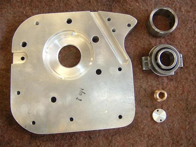
plate 2
.JPG)
|
|
|
clairetoo
|
| posted on 14/7/08 at 08:50 PM |
|
|
I made my own adapter plate to fit an Mx5 box onto an Mx3 V6 (picture in my archive) , I did it by first making a template from MDF with a hole to fit
tight over the flywheel , first spotting the engine holes , then fitting the clutch to the flywheel and with the gearbox stood on end , I used the
flywheel to align the plate .
I then just copied it on to 20mm ally plate .
Its cuz I is blond , innit
Claire xx
Will weld for food......
|
|
|
trogdor
|
| posted on 15/7/08 at 01:50 PM |
|
|
I am facing this problem too, i have a ford v6 that i need to mate to a transaxle of some kind, most likely an audi transaxle.
I have the original v6 transaxle gearbox so am planning to lop the bellhousing off that and off the audi and weld where the audi's bellhousing
was. Would obviously need to get it aligned etc but my main issue with this is that if you break the audi gearbox you would either have to rebuild it
or start the process again with another box so it is tempting to make a plate. Although if i can find a transaxle with a removable bellhousing then
this prob would be solved.
|
|
|
mr henderson
|
| posted on 15/7/08 at 02:32 PM |
|
|
Why not use an Audi V6? There's plenty of them about and some of them are quite nice.
Or, I've got a 1.8t that might fit your transaxle, going cheap (£500)
John
|
|
|
Matty Dog
|
| posted on 16/7/08 at 10:38 PM |
|
|
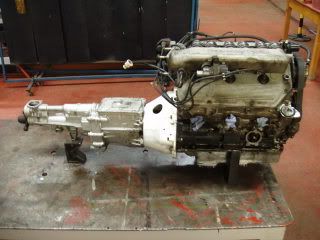
There is a chap in New Zealand who makes adaptor plates to put a Supra gearbox onto the Lexus V8 motor.
This conversion uses the bellhousing that came with the Lexus motor with an adaptor plate between this and the Supra gearbox.
In some instances this may be a neater or easier solution.
|
|
|
tobym
|
| posted on 18/7/08 at 02:45 PM |
|
|
quote:
Originally posted by Matty Dog
There is a chap in New Zealand who makes adaptor plates to put a Supra gearbox onto the Lexus V8 motor.
This conversion uses the bellhousing that came with the Lexus motor with an adaptor plate between this and the Supra gearbox.
In some instances this may be a neater or easier solution.
Do you know if he operates online/has a website?
|
|
|