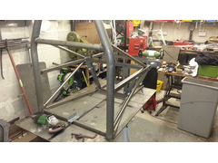

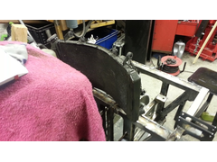
start of build rear view
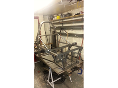

rear view from the rear

Hello All tried to post this before but ended up in for sale !
I'm new to this forum , but not new to building cars , Bikes , ect
I am currently building a totally unique single seat road car of my own design.
I'm a big chap ( both up and wide ) and was looking at first to convert a formula car.
then hit a problem " I cant get in a formula car " as there all built for, shall we say normal size people.
my back ground is engineering and I am reasonably proficient with cad.
I had built several highly modified westfield 7's before
I started out with a 2 seat EXO type car , played around with that idea for several months .
then decided that how ever you design an exo car its always going to be Ariel like.
so then decided to go single seat exo car , did not like anything I designed . so ended up with a formula type chassis.
I did several complicated designs that whilst stiff ect were going to be difficult to fabricate without the aid of a fixture.
so I went back to the drawing paper ( well cad screen ) and redesigned the car with ease of fabrication in mind.
to this end I used laser cut panels joined via round tube at first and then later square tube ( again to aid fabrication )
all the major tubes are located via the laser profiles and they also provide the suspension location.
any way to cut a long story short if any one is interested , I will post more and plenty of pics
I have the basic chassis finished and engine in / out / ect
and just about to start the suspension fabrication.
ps someone needs to tell me how to post pictures ect as I have know idea
I have tried to post pictures having a few problems
do I need a web site to post from or can I upload directly to forum .
also I cant seem to add a new conversation just edit the current one . I know i'm thick but never posted before.
[Edited on 7/11/14 by bart]
I'd love to see it but no idea on how to do photos!
The art of photo's
It will only accept limited files so save and upload as .jpegs
Do not use any clever characters in the file name, just letters
Keep the pictures small
So now you know the gotchas at the top left hand side you will see the tool bar, click on photo archive, this is you archive, then you have a choice,
new folder and below this add photo, you can load directly into your archive or have some sub folders, to load the picture then click on choose file
and navigate to your picture and put in a brief description then tap upload
Regards Mark
ok stuck now
I have managed to upload a few pics to start into my archive
but can find no way of getting them in the post ?
help newbie .


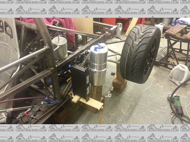
start of build rear view


rear view from the rear
Open the picture in your archive, copy the URL above the picture and paste into your post 
Above the picture it says 'forum code'. Just copy and paste that into your post like this


start of build rear view
As above, bit slow on my reply as forgot to add the how to in first post. Been a long day
good luck
[Edited on 7/11/14 by AndyW]
[Edited on 7/11/14 by AndyW]
ok someone seems to have posted my photos for me
neat trick !
so hear goes first pics
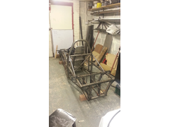
this is the start of the physical build
rear of chassis from roll bar and from the back
[img]


start of build rear view
[/img]


rear view from the rear
ill convert the rest of the chassis pics over the weekend and up load them
[Edited on 7/11/14 by bart]
later pics of chassis from front and rear
at this stage it is more or less complete
I just had to "I" beam the laser cut profiles to give lateral strength
later I changed the front design.
[img]
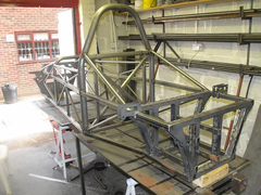

later in construction
[/img]
[img]
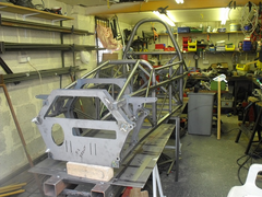

later build front view
[/img]
don't know how much detail people want
engine is Hayabusa gen 2
if anyone wants any further info would be happy to post.
[img]
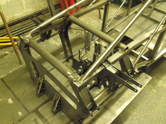

new front design
[/img]
new front end design ,
Fantastic looking build, what engine will you be running and how will running a single seater limit you for track days etc?
Hayabusa gen 2
standard to start of with then turbo after iva
has some mods now but basically std engine
I understand some tracks allow road legal single seater , not that bothered
as it will defo be road legal
Looks interesting.......you couldnt give enough details to us in here so dont think your bore us so give us every little bit!!! 
Its really good to see scratch builds with good engineering. More detail the better. 
I think it's a bit complicated for a road car, but a good build.
What thickness are the lase cut panels and are you going to reinforce the edge against twist?
Is that a spring/rocker mount sticking out wide between the front wishbone pick-up points?
I know it's the 'done thing' to have the feet behind the front wheels, but you have a lot of wasted space between the pedals and front
bulkhead.
The tube from the rear, front suspension mounts and going to the dash bulkhead, tacked onto the side member seems a strange way to do it. I always
have a feeling that single side welded joints are trying to split the tube as it leaves the stress line only on one side.
all location plates are 3 mm ( but in future I would take this down to 2.5 or 2 with local reinforcement )
apart from the front plate , they as a pair way less than box tube and brackets
has the added advantage that every thing is in the correct place , no measuring on assembly. I just made some spacers to go between the plates . as
regards to reinforcement I have inserted "I" beam plates between them made from 1mm ( was going to be 0.6 but I had welding problems . this
has proved as per my calculation to be extremely strong.
I did change the front as I felt when first done the front was a bit "floaty" new design is no less stiff and looks better. also had the
added bonus that it dropped the line of sight to the front of the car ( whilst sitting in it and making brum errr brum noises )
added length came from my preferred width / length ratio. and only added 2 kg to weight .
the bitts sticking out are the locations for the shocks bot not all as also the light brackets . again I beam boxed for strength.
car has out board suspension for now , will move to inboard on my mark 2.
also during the physical build I can see where to take out 20>25% of weight from the chassis , weighs 62 kg with all brackets.
as for complicated . I beg to differ took me only 16 hrs to fabricate the bulk of the chassis , and that included cutting all of the tube .
I have now added a structure to move the brake pedals back and forth for shorter mates to drive as the seat is fixed ( thick cushions provided for
real short mates )
I have done a crude bending moment test , with frame supported either end and 150 kg + ( yes that's me ) bouncing up and down at the roll bar . I
measured 1mm flex in the chassis , I find this measurement acceptable , I would like comments on this though , with a normal man 75kg I had on 0.4 mm
with a bounce . I understand that the 7 type chassis is far more than this according to some white paper I have read.
as far as the suspension is concerned this was ment only as a design test bed for a later improved version . just wanted to test the suspension
geometry and general build. besides I don't like where some inboard assembles go during a crash !
[Edited on 8/11/14 by bart]
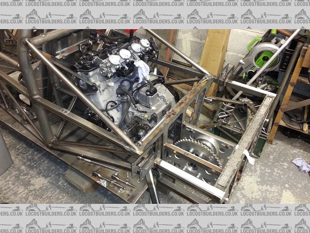
hi again pictures of engine in the frame and the sliding frame for the diff.
and yes i know the welding not that hot . im a engineer not a welder .
my welding varies from , ok > to what c--p
but i always make sure structural welds are well fused , they just don't look nice .
these pics was before i boxed in the suspension mounts so yes the do look flimsy
[img]
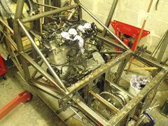

engine in frame with diff
[/img]
[img]
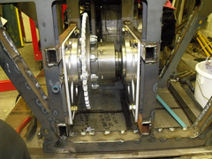

diff mount from the rear
[/img]
i also have a shopping list so if any one has the following parts i would be intrested
have a few things i need
paddle shift , mechanical or electric
side exit Hayabusa exhaust manifold ah la grass racing type
catalytic converter for iva pass
alloy 13" ford pcd wheels 35 ish offset
all in one headlights.
Quaife reversing diff , later 8 wheel design please
i know its a big list but if you don't ask then you don't get !
[Edited on 8/11/14 by bart]
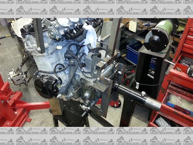
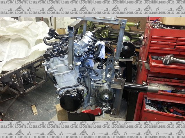
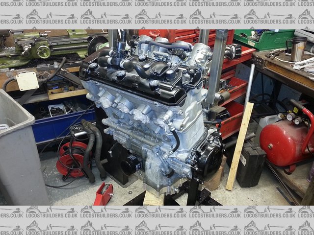
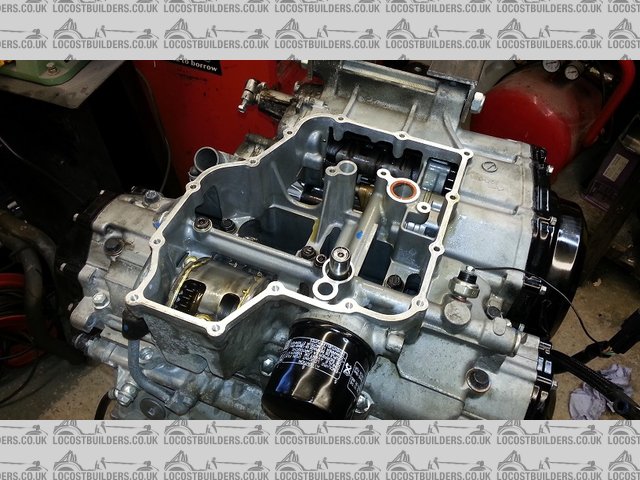
ok I decided I needed to make a turn over fixture for the engine so I can
do the sump and stuff.
also made a three legged "milk" stool as there is no longer enough room in my garage for a garden chair.
also made the brake adjustment area , so the pedals can be adjusted as the seat is fixed apart from adding cushions ect
also my kirkey seat arrived and I made a fixing frame for that in the car.
I also added side adjustment on the brake box so that I can get it just right.
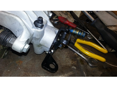
ps: I also stripped my rally design escort steering rack ready for shortening , if any one is interested I will post pictures on how to do it , but
i'm sure it has been covered many times before. ps they are very easy to do !
[img]
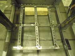

BRAKE PEDAL ADJUSTMENT
[/img]
picture of brake pedal adjustment area
[img]
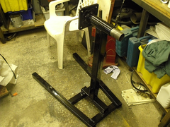

diy engine turn over
[/img]
engine turn over home made
[img]
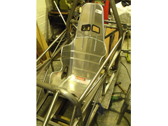

kirkey seat
[/img]
kirkey seat , very good quality , not worth making myself
[img]
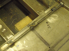

kirkey seat frame rail
[/img]
kirkey seat mount frame , front of seat
[img]
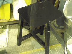

milk stall
[/img]
my three leg milk stool , much smaller and more convenient to use / move around .
my wife nearly divorced me as I put it in the lounge to dry and it stank the house out !
How long is the pedal adjustment area?
about 6" max just looks like a lot of holes as it bolts at the back and the front of pedal box.
some of the holes at the back I will never use unless I get someone 7 ft 6 in the car , got carried away drilling the holes.
hey hoe , never mind. I also did not have the seat when I did it so it was a bit of a guess where it was to go exactly.
I also allowed for a reinforcement bracket if it feels a bit flexi when in operation
[Edited on 12/11/14 by bart]
Most trackdays will allow single seaters if the wheels are covered. I hope that doesn't chnge as my long term build is a terrapin single seater!
quote:
Originally posted by prawnabie
Most trackdays will allow single seaters if the wheels are covered. I hope that doesn't chnge as my long term build is a terrapin single seater!

just come in for the night
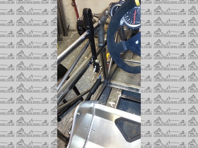
managed to get the hand brake lever in place , bit tricky that in a single seat car.
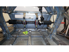
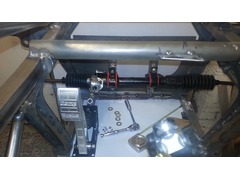
finished shortening the steering rack and mounted to the car .
I can now start to see where i'm going with the steering wheel / column etc..
seem to not have progressed very far today , lots of time spent thinking and drinking tea.
started to make the fixture today for the suspension arms , got the main plate marked out . then got called for dinner/tea.
good job as I would have been out there till midnight "its a hobby" and the wife likes to talk to me now and again ( blah blah , yes dear ,
yes dear cause i'm listening )
pics to follow .
I need some advice on a gear lever , ratio's ect any advice anyone .
cant decide whether to build a mechanical flappy paddle on go stick , this would be right next to the steering wheel !
also cant decide about the radiator , rather than go expensive custom I was thinking use 2 Hayabusa ones ( already have one )
and they can be picked up cheap , any one done this ? or seen it done .
thought I would post some pictures of the design history
when I started It was a 2 seater exo
then as I progressed it became a single seat
did about 12 designs before settling on this one
I know its not complete but I only draw what is unique ie: if lh and rh are the same or symmetrical then I only draw one side.
I have not designed the body yet , felt I would get more of a feeling with a chassis in the flesh.
first pic is the old 2 seater , missing chassis bracing ect
this had a Subaru engine /gearbox , which is for sale any one , and lots of other Subaru parts.
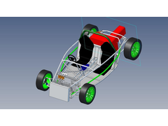

Description
second picture is current design , but does not show the updates I have changed / incorporated
when the weather finally goes horrible I will take the time to redraw / model the car as I have built it
but its not far off the finished thing
Description
Looking very good, if only I had the ability to draw my stuff in 3D!
hello all
latest update
I spent the last few days making a fixture that make all the suspension arms
made from a piece of aluminium plate that I retrieved from a scrapped printing machine some 10 years ago
"I new it would come in handy one day
this will make all four different arms
only the front lower arm is handed for the fixture so I just flip the end over and it makes a rh and a lh
all the other arms are handed from lh to rh but are the same in the fixture " just flip them over when finished.
so far made the lower front and the upper front
could not wait to make the rest so broke off and assembled the front suspension . works perfect .and all lines up.

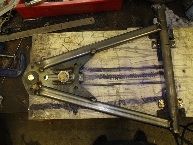
Description
jig fixture

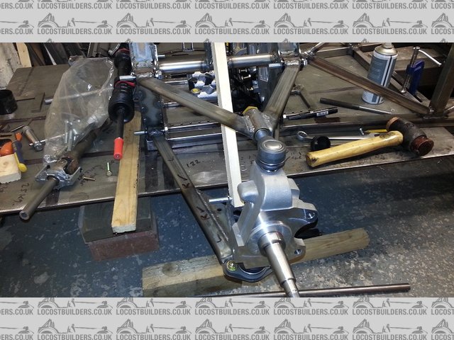
Description
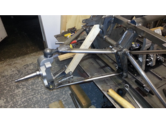

Description

Description
front lower arm outside cooling down
top tip these are very hot when you pic them up without a glove ! , but you soon put it down again
Bart- "Cousin Jonathan" type here- wonderful build you have on there! Sooo many questions! Like the other guy said, you probably can't
bore us with too many details!
What are the front spindles from, or who produced them?
Can you give some details on the ovaled tubing you used to make the front suspension A-frames?
And don't stop! Great stuff! Colonial Boy Chris
hi
the uprights are hi spec as are the brakes ands disks . I brought them as a complete 2 corner set
the oval tube or obround is 30 * 15 erw . did a few calcs and this should be fine
the rear is 1" seamless as under far more stress from drive.
looks very good  interested in how it looks at the end with the bodywork
It you take loads of photos and Cad drawings and we could finally have the Haynes single seater...yeah!
quote:
Originally posted by prawnabie
Most trackdays will allow single seaters if the wheels are covered. I hope that doesn't chnge as my long term build is a terrapin single seater!
Looking good.
Is that an ally camber adjuster in the top wishbone? There have been several failures of those with it shearing under the hex'.
hi
yes it is an alloy adjuster , thanks for letting me know
I will have to get some stainless or steel ones
do you know of any one that sells them.
if not I will have to make then , and that's already a long list so if I can buy them all the better.
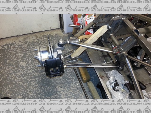
hi all
well I should have been making the rear suspension arms , but like a 10 year old at xmas
I could not contain myself putting the front uprights together for a full fit up check.
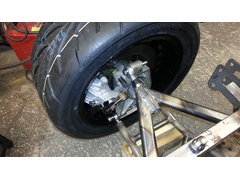
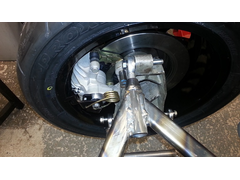
so hear are the pics of the lh front complete
[img]

Description
[/img]
[img]


Description
[/img]
[img]


Description
[/img]
looking great, would like some front hubs like that on mine!
Geat build I look forward to seeing you progress.
ok all
had Wednesday off rest the brain , although I did have several idea's during the day !
Thursday was a bad day , just seemed to achieve very little and did no enjoy it.
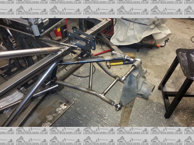
had a good day today : made the fixture and made the rear suspension arms
and just fitted the lh side for a trial
some pics of the event .
[img]

Description
[/img]
[img]

Description
[/img]
[Edited on 21/11/14 by bart]
Bart- Thanks for info, however I'm still not sure or a source, Stateside or in your neck of the woods! Also, your rear uprights are another
question!
Don't slow down! Answer when you can, and thanks for a tremendous build experience! Chris
Great progress! Looks really nice.
Just one observation. Have you got enough camber adjustment on the front? There don't seem to be many threads left on the top drag link.
think so
was designed with 1 deg
and should have another 1 deg to go
if it does prove to be a problem I will have to take a little of the bush at the top
its a bit deceptive , its only roughly put together to check fit etc. I think the front already has about 1 deg in the picture.
must admit I was a bit wary about to much thread hang out.
worst case scenario I will have to make some new top arms
I now have a jig that is fully adjustable so making new arms would only take 2 hours
"the joy of a proto type" fit take apart , adjust , fit , take apart . adjust ect ect ect
I have decided to fabricate steel rear uprights , will make them to the same dimensions as Westfield to take vw calliper's
with the brake disk not being so deep as normal don't think there will be much weight penalty. and be considerably stronger.
I have here'd that the Westfield rear uprights brake ( crack) > can anyone confirm this ???????
ok just rushed out to the garage for a check
with full adjustment I have 1.6 deg
anyone use more than that ????
ok looks like it's a bit of a mod on the front top link. car was designed to have as little roll possible. think i'll go for 3 deg max for
now.
in all the reading I have done , figures of 1 to 1.5 deg was mentioned
[Edited on 22/11/14 by bart]
I run around 2 degree of camber.
I am not expert on suspension design but I guess the amount you will need static would depend on how much it gains in role?
If I remember correctly the Caterham 620r runs around 4 degrees!
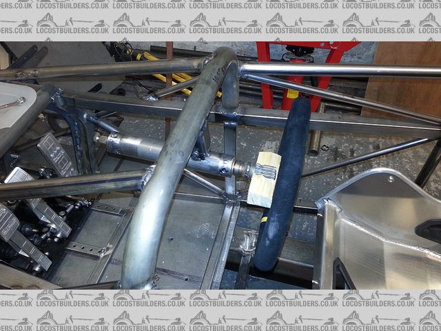
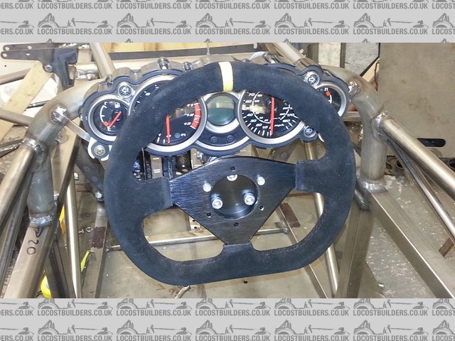
had a temp fit of the steering wheel just to get proper position
now making the column complete one off due to fit problems
one piece of good news the steering wheel to side walls is less than 127mm both sides.
[img]
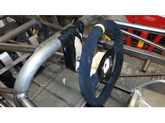

Description
[/img]
? do you thick it would pass IVA with block o wood and gaffer tape !
also went down and picked up the wheels and tyres "£200" the set . ( for the wife ! )
[img]

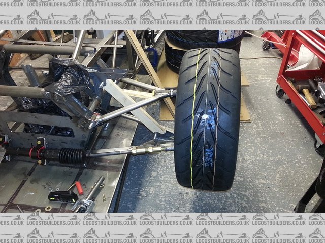
Description
[/img]
all 15" 195/50 front
225/45 rear
FYI
been doing lots of little small jobs , I never have a good day when doing these but they need to be done.
1) made the seat belt anchor threaded tubes
2) altering the rear westfield uprights to take fiesta drive shafts
this includes fitting different size bearings.
fiesta hubs need machining - 0.5 mm on rear face
uprights need 2mm machining of front face
3) slight mod to allow full suspension travel at the rear , small cut out of the frame , I will reinforce this area later.
4) worked out that I need 150mm steering extensions for rack , did a quick drawing , will make them tomorrow.
5) drew up the steering column . will make that tomorrow as well.
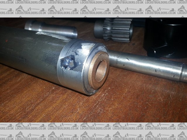
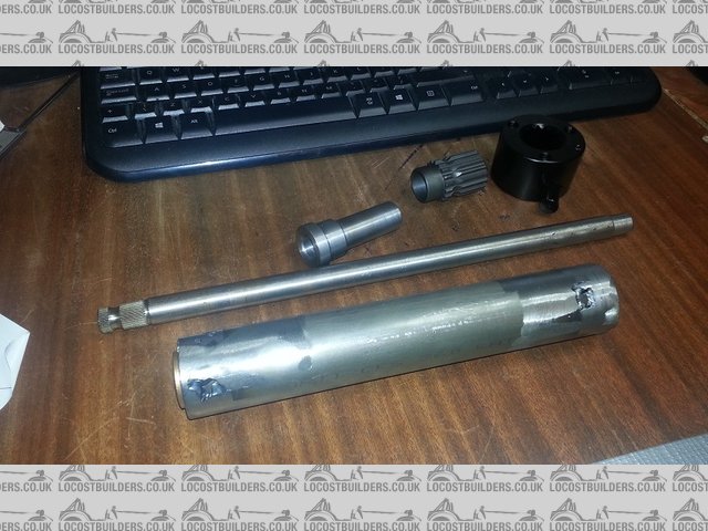
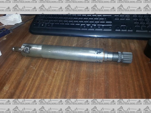
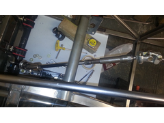
hear are some pics of the steering column that I have made
made from 1 1/2" 1.5mm tube
some made bushes
2 oillite top hats
adapter for inner shaft to quick release
any questions feel free
[img]

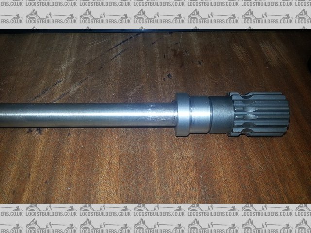
Description
[/img]
[img]

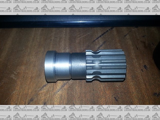
Description
[/img]
[img]

Description
[/img]
[img]

Description
[/img]
[img]

Description
[/img]
I also changed the bearing's and adapted the westfield rear uprights to take fiesta drive shafts.
if any one is interested let me know I will post details .
also made some 150 mm extensions for the steering rack.
hello all
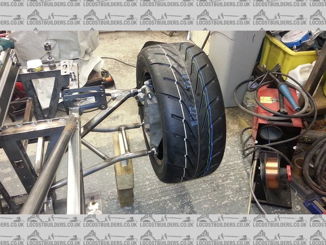
posting 3 pictures tonight showing the rear corner build up
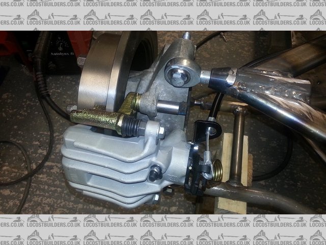
I have now adapted the westfield rear upright to take the fiesta drive shafts and fitted the VW brake calliper's
the calliper's need a little tweaking but they are 90% there . changed the escort front brake disk I was using on the rear
to a bigger ford disk to match the calliper radius. (270mm) and a better offset to boot !
found all the specs I needed on the apec brake site , you can search by size and make fantastic reference source.
need to alter the hand brake mechanism a little to miss the upright.
also considering fitting the calliper's to the wrong sides they look to fit better this way.
my only concern is bleeding the brakes as the bleed nipples will be on the bottom.
I can always take the calliper of its mount to position for bleeding , we will see !
next tasks are
position steering column
measure for coil overs
weld up and finish front steering area ( just tacked in place to test )
work out full steering links to include a crush part.
fit up engine.
fully fit up all four corners
look at and decide on gear change
finish seat mounts and seat belt mounts
that should see me through this week
looking to under coat the chassis so if any one has suggestions for the best self applied paint please post your suggestion's.
[img]

Description
[/img]
[img]

Description
[/img]
[img]

rear fit up showing all
[/img]
Cracking build. Have you got any ideas for the bodywork ? Perhaps you could use the BAC Mono for inspiration.
not sure on body work yet .
thought I'd finish chassis to at least rolling stage then have a good think
easier to get a view when its all there in 3d in front of you.
maybe take some suggestion's from the forum.
hi all
I am at the stage when I need to rivet the alloy floor to the frame
? what to use
I intend to use 1.5 mm half hard aluminium sheet and 4mm c/s aluminium pop rivet's with silicon sealant between.
any comment's would I be better using large head rivet's ? or steel rivet's ect
any advice welcome.
I have posted this question as a separate post as well , as long as I get some answers not bothered where you answer
I used stainless steel rivets for bulkheads/floors and ally rivet for non-structural stuff on my first sprint car build. All has been fine. I'm a
bit of a fan of large head ally rivets as well, just neaten things up.
Enjoyed reading your build thread, you progress is fast! I'm planning to run mine at the end of 2015 for a shakedown and then in proper events in
2016.
What I really like though is that two people with the same goal are building such different cars. Will be following the updates.
hi all
had Saturday off / just did not feel like doing anything , ate and slept on the couch whilst my wife went to the sales.
Sunday arrived and after some food shopping I decided that I must do something
first of all I measured the shock absorbers full extension and max closure ,
this is so I can get in on the group buy of protect shocks.
on to the VW rear calliper's
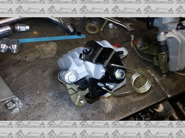
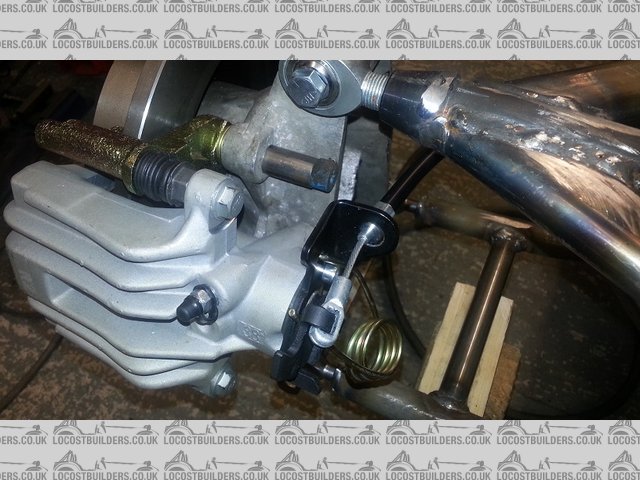
I had a small problem . when mounted the pull cable for the handbrake would have fouled the rear of the upright casting.
mounting the left calliper on the wrong side and the right visa versa sort of solved it but I was not happy.
probably why I did not feel like working Saturday.!
so came up with a solution as shown in the pics
first pic is as ! the pull brackets extend in to the bracket.
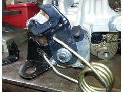
so I took the brackets of put the lh on the rh and the rh on the lh
I also modded the swing bracket part, took the off set out and re welded together.
and hey presto ! the bracket is now offset away from the calliper , effectively moving the cable approx. 35mm further out from the calliper. well
happy with that solution. one of my better idea's
re - my fast progress ( previous comment ) > I only tend to do about 3 hrs physical work per day as i'm older and unfortunately don't
have the stamina these days . you know the mind is willing the body is ******d !! 
[img]

Description
[/img]
original config of brackets . off set into caliper
[img]

Description
[/img]
lh swapped for rh
[img]

Description
[/img]
showing offset away from calliper now .
this also allows me to fit the callipers on the correct sides , making bleeding much easier.
second post tonight
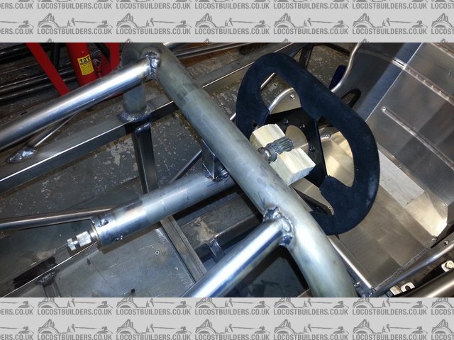
I forgot ( old age ) I also trial fitted the new steering column that I made on Thursday
only a temp bracket just so I can get the position exactly correct . took it of and modded it half dozen times.
I can now design a bracket that has a small degree of adjustment , back and forward say + - 20 mm up down +- 20 mm

Description
[img]

Description
[/img]
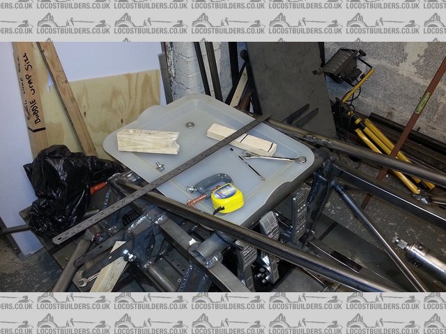
also I have decided to build in and fit the worlds first " SPEED TEA TRAY " somewhere to keep your BREW when doing a fast track day. I might
apply for a patent on this idea

Description

The styling I was talking about. Anything similar and you'd be onto a winner IMO.
Underneath pretty similar to your car really.
[Edited on 1/12/14 by wylliezx9r]
the thought had passed my mind !!!!!
but will I be able to still fit the tea tray ?
[Edited on 1/12/14 by bart]
Why stop at the tea tray ? Go for a picnic table instead 
[Edited on 1/12/14 by wylliezx9r]
Why are there heat marks on the upper rear wishbone tubing at the mid point?
You must think about the steering wheel, it's not as simple as we think as vertical wheels are tiring to the arms. This is beecause, in real
life, we actually steer by pushing and pulling on an angled wheel not by turning. Turning a vertical wheel, without any power steering, is hard.
re heat marks on top arm
its only on one arm , for some reason this arm had the bushes slightly out of alignment when finished also slightly to narrow
so I spotted the arms to bring them back.
I may remake this arm not sure.
re steering wheel
in the picture the temp bracket had dropped the wheel will in fact be angled . was just held in with a temp bolt in a big hole so I could move it
about to feel correct.
did not achieve much today just lots of measurement and planning to move forward , ordered some bits ect. progress tomorrow with luck.
[Edited on 1/12/14 by bart]
hi all
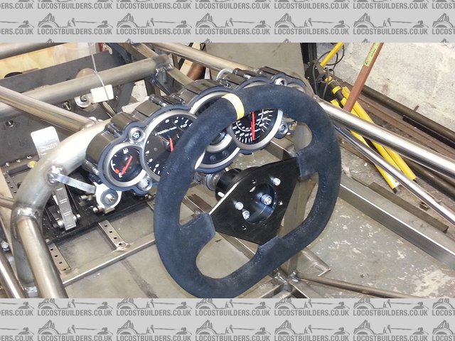
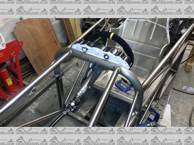
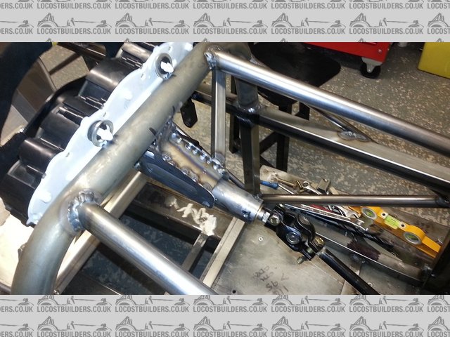
mounted the steering column and the clocks today along with lots of small jobs
had to make a bracket for the column . its in and working will need a side brace stiffener
1) did the seat belt mounts
2) finished seat mounting points
3) finished of the handbrake mounting posts
4) had a sit in the car several times to get it all correct ( with appropriate noises ect )
now some will notice that the clock are partially obscured by the wheel. yes you are correct for iva it will have to be bigger and none removable
going to make another inner column to take an iva steering wheel. there answered that one before anyone spotted it .!!! 
tomorrow's list is finish the steering rack area and reinforce .
run the hand brake cables for position brackets ect.
gear change lever position and make.
steering column intermediate bearing
assemble all the rear suspension both sides and measure up for extended half shafts.
so ! easy day tomorrow.
todays pics :
[img]

Description
[/img]
[img]

Description
[/img]
[img]

Description
[/img]
Looking good Bart, keep it coming!
hi all
well big list today , but did not get all the list done , in fact the list got shorter as the day went on.!
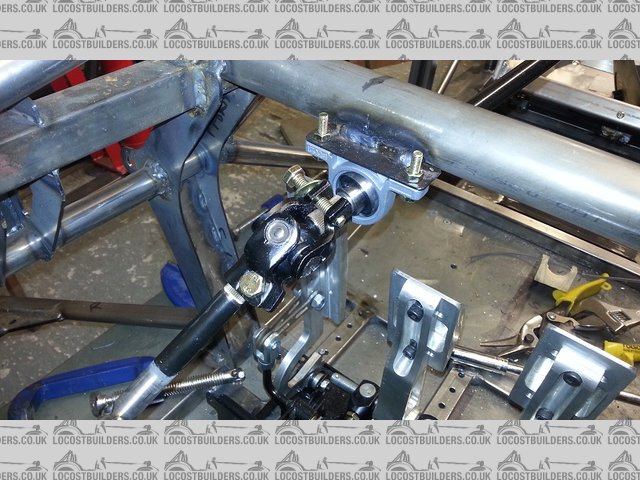
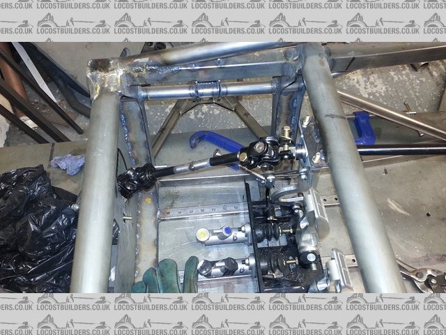
completed the steering column added a ctr support bearing for the steering shaft
boxed the support bracket for the steering column.
and added a side support
checked all the angle's on the steering knuckle's.
installed the bush for the gear change .
in the below picture's the hand brake will fowl the gear change , did not see this when I took the pictures
all done at the end of the day.
only when editing the pictures for posting and then checking when having a clean up .
still I have a solution so tomorrow will change ..
[img]

Description
[/img]
[img]

Description
[/img]
[img]

Description
[/img]
[img]

Description
[/img]
hello all
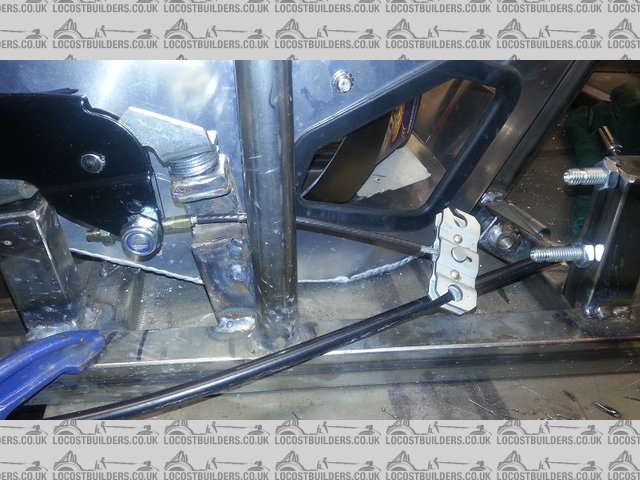
today I made and installed the full handbrake working mechanism
and temporarily run the hand brake cables
you can now see when install what I was jabbering on about earlier about altering the hand brake brackets
they now miss the upright casting by a long way ( yippee!)
I also measured the installation of the half shafts and have the measurements to send off.
I altered the gear change but forgot to take a picture ( will post tomorrow night )
I also took possession of an exhaust for the engine . unfortunately it is to far forward for my use so its up for sale same price as I paid £60 +
postage ( no international sorry )
apart from the picture it comes with a silencer as well , so anyone interested u2u me
[img]

Description
[/img]
[img]

Description
[/img]
[img]

Description
[/img]
[img]

Description
[/img]
[img]
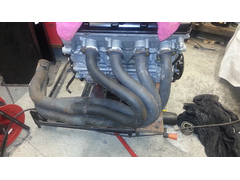

exhaust
[/img]
this exhaust is for sale !
quote:Bart - that looks like a Sierra cable, the Golf one should look like this:
Originally posted by bart
hello all
today I made and installed the full handbrake working mechanism
and temporarily run the hand brake cables

thanks for the hand brake info
the one in the picture was just a fit and see , I shall be making custom cables to finish.
nice to get response though .
No problem - took me ages to finally get my handbrake sorted with the right cable/lever combo. Should have been easy (it's a Westfield after
all!) but my choice of parts veered from the designed version, so been through a few variations!
All done now though 
Bart,
I know that most people use 1.5mm but I have always used 2mm or in places 3mm and have never regretted it, it withstands impacts much better and seems
to beef everything up. I also use PU adhesive and not silicon as silicone whilst making it waterproof adds very little to the bond in comparison to PU
which does both, just have a look on EBay or the like for PU Adhesive or sometimes referred to as Body-kit Adhesive. Latest iteration of the Tiger now
has a composite floor of carbon Kevlar and foam core and that's about 8mm thick but has added substantially to the stiffness of the chassis. Oh
and big head rivets are the way forward! I bought a big bag of bright orange 10mm head ones ages ago and am on the lookout for more as I'm almost
out :-(
HTH
quote:
Originally posted by bart
hi all
I am at the stage when I need to rivet the alloy floor to the frame
? what to use
I intend to use 1.5 mm half hard aluminium sheet and 4mm c/s aluminium pop rivet's with silicon sealant between.
any comment's would I be better using large head rivet's ? or steel rivet's ect
any advice welcome.
I have posted this question as a separate post as well , as long as I get some answers not bothered where you answer
bart - Sikaflex 221 for floor bonding
I used a lever from a Rover 2/400 as the mech was a lot more compact. For the cables I found the Freelancer has nice fat beefy cables that fit the
quadrant. Both from one side, the short one as one side is longer than the other. I'm now in possession of a lever from a Range Rover, no idea
what year but its even smaller than the the 200 one and would be ideal for tight spaces.
Keep up the good work.
hi all
started work again today
made a start on the gear change lever and is ready for welding , then machining
then had a think , I need to put the engine back in to get all the brackets finished and shimmed
also the engine needs finishing
swing sump
clutch springs ect
so I made the decision to spend the rest of the day making the cradle to put the engine in the engine turn over I made before
in the pics you can see how I made the adapter , I took an educated stab at the ctr of gravity.
well I good not have got it closer no mater how many times I could have tried.
it take no effort atall to turn it over , Near Perfection  !!!
!!!
by this time the temperature was plummeting and I could not feel my toes , so it was in for late tea - dinner and a rest
next step prep engine and design fuel tank to be made Monday / Tuesday
looking to put engine back in Wednesday if all goes well.
the car at that stage will have all the suspension on so I may be tempted ( read as defo will ) weigh the car
I can allow for all the bits not yet fitted , so I will have a good idea of total weight
i'm betting 450kg with body when finished ,
as stated before I am aiming for a end of February date for completion of mechanical work , then its onto body

Description

Description

Description
if anyone shows interest I will take some pics of engine prep build - wet swing sump - baffle - oil pipes - clutch
if no one needs to know I wont bother just get it done.
[Edited on 6/12/14 by bart]
well today was stop start 2 steps forward 1 step back.
put the swing sump kit on the engine and stripped the clutch ready to uprate and put a baffle plate in
had to stop when I realised I needed a clutch lock tool
so put it back together for now and put the engine back in the car , no small task on my own .
had a quick ponder on what's to do next and called it a day.
ps: the swing sump kit needed some small mods to make it fit _ was a little upset about this as it was expensive
it was from extreme engines , but i'm pretty sure its a rilltech item due to the large r on the bottom.

Description
engine cleaned ready for installation

Description
swing sump and baffle installed

Description
showing mods to oil return pipe and the swing arm itself

Description
engine back in.
with hind sight I wish I had left more space between the engine and the roll bar bulk head , I can get an exhaust in there but its tight , very tight.
we shall see it arrives Monday / Tuesday.
aiming to get all the bits that I need to order and get made organised tomorrow so that I can continue over xmas and new year .
aiming to get any bits that I need to order / get made sorted tomorrow so that I can continue over the Christmas.
Can that sump pickup swing a full 360 degrees? Might just be the picture but looks like it'll foul on one side?
Can only imagine that'll mean when jumping on the brakes/throttle in left or right corners (depending on which side fouls) the pickup will fall
against the side of the engine and jam and leave you in a worse position for pickup than if you just had a normal central one..
James
it has built in stops
swings about 110 degree
not good! 
go ahead explain more . ill take note of any advice
Found an image which I guess is a similar setup - perhaps a busa
Consider the following condition - accelerating out of a left hand bend

The pickup would be forced against the stop - and not provide any benefit (in fact probably slightly worse than a well baffled sump with a central
pickup... This could arguably occur even accelerating in a straight line
James
[Edited on 7/12/14 by cloudy]
mmmmm need to think this through. thinking cap
on

any body out there runing
one of these sump ????
[Edited on 7/12/14 by bart]
well massive relief the exhaust fits
picture of the exhaust manifold ( not in my car ) .
when I finish the whole installation this will take some time , I will post full installation pictures , need to mod the system to fit a cat ect .
big relief though did not know for sure if I had enough room .

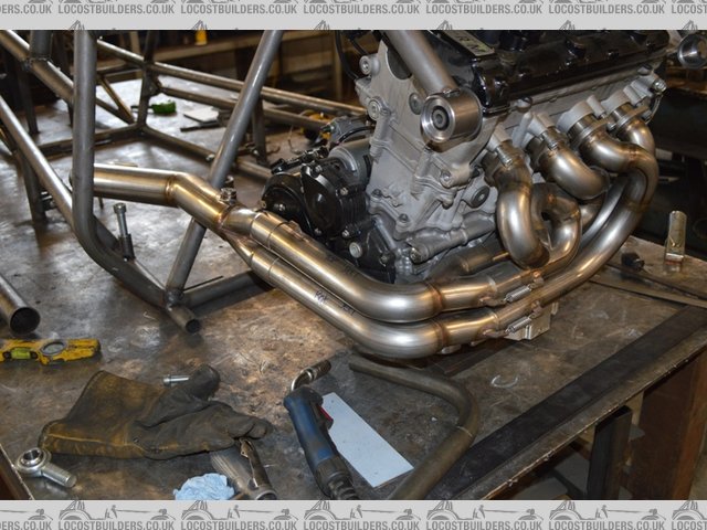
Description
same system just not on my engine / car
nice job 
quote:
Originally posted by bart
mmmmm need to think this through. thinking cap
on

any body out there runing
one of these sump ????
[Edited on 7/12/14 by bart]
Best thing since Cloudy's R4 
That KTM design body work would look so good.
hi all
thought I would post some pictures of the design process I went through
this is a balsa model of a 2 seater I was thinking of , although the top rails a straight in the model
they would have been rolled radius in the real car.
I built this some 7 months ago to get a FEEL for the construction and rigidity of the chassis
and what happens when you add / take of bits
all I can say about this design exercise is , yes it ends up looking like an atom / warner r4 / mev ect
if you go down the exo route I suppose its inevitable.
that's why I ended up not building this design . I wanted to be a little different.

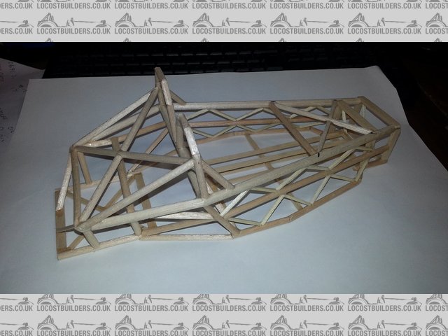
Description

Description

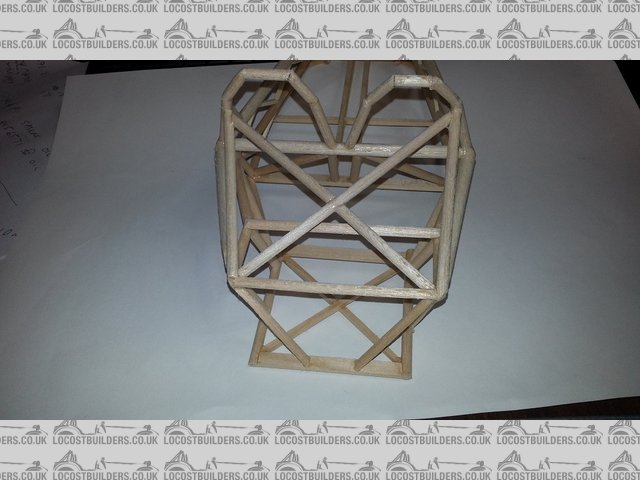
Description
as I say this was just a snap shot off one stage in the thought process .
ps : I did not mean to insult anyone's designs , I know a lot of hard work and thought went in to all of them.
I was just explaining how I got to where I am today .
phew !!! dodged that one !
hi all
had a day off yesterday , needed to refresh the brain .
today I set about designing the fuel tank , that will be off to manufacture tomorrow .
could not decide how to mount it but problem solved now.
have found a fuel gauge sender that can be modded to work with my bike clocks.
any one need the info just u2u me
the rest of my exhaust bits arrived to day so I will be changing over to stainless wire tomorrow and tacking up the exhaust
the tank has a baffled sump with open dimples and a side baffle as well
holds 36 ltr ( or so my cad says )
making from 1.5 mm ally with 6 mm mounting pads that attach to rubber cotton reels
all gets loaded into the car from below.
I also need a double skinned insulated fire wall between the exhaust and the tank and a fire wall between me and the tank.
also measured up the gear change cable , that is on order with venhill with some other bits I need.
so all in all in been a measure and organise day today , which is just as well as the weather outside is horrible .
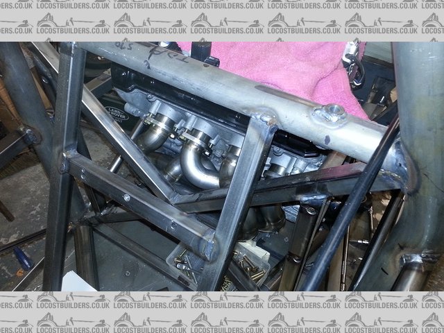
if I can summon the will to go outside to the garage I will put up some pics of the installed snake exhaust manifold
Description
well I had to go outside and lock up so I took the pics I said I would.
these show the installed snake manifold .
yes ! at the moment I think its to tight to the block so I will be tinkering tomorrow / Friday to move it a little
have already started to mod the collectors to take them outside the rear frame ( all will become clear later )
I also need to add a cat witch arrived today.
you can still see the manifold through the chassis as I have not installed the fire wall yet ( job on list for xmas )
I have also shown the proposed position of the back box although the exit is not correct.
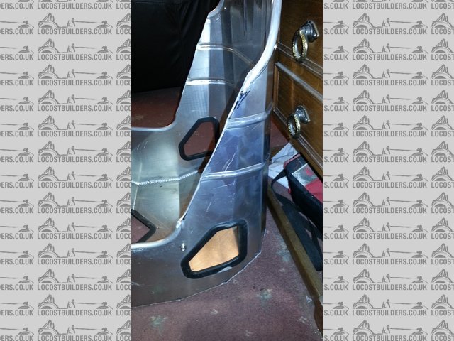
last pic show a mod I made to the seat , I took the underarm wings of and will be welding the rounded trim back on .

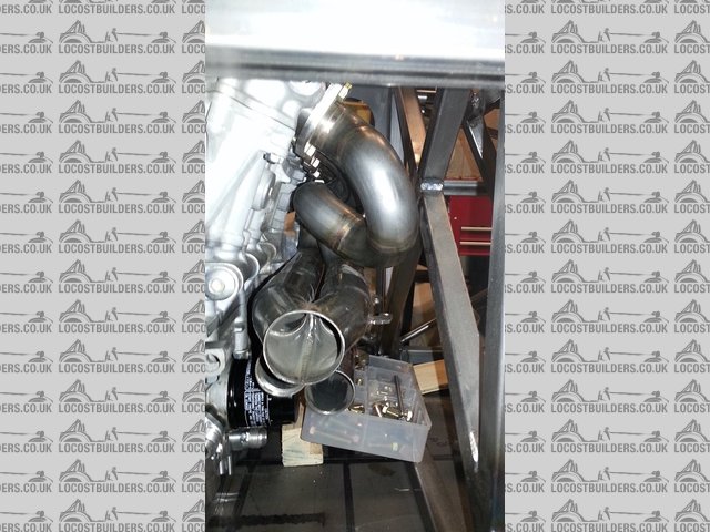
Description

Description

Description

Description

Description
hi all
spent the day finishing ( apart from radi for iva ) the gear change lever , added 2 alloy bosses got them welded . machined the lever out for swivel
bushes and put some more holes in , just waiting for gear change cable and 6 mm rod end.
need to spend a couple of hours making it all rounded for iva though.
got stuck into the exhaust.
turned the secondary's round and re welded , keeping the length the same.
this takes the system out side the car as per the picture.
I will add the cat tomorrow when the lambda sensor bosses arrive ( I hope , xmas post ! )
will mount the back box to the frame and more or less finish the system.
I then have to take the engine out and alter the headers slightly , then back in and finish the exhaust.
the cat is some way from the head , so I will wrap the system to keep the heat up at the cat , also to keep the fire wall cooler.

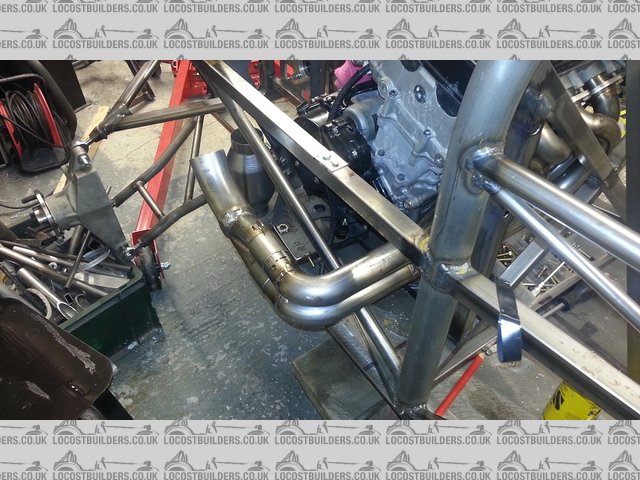
Description

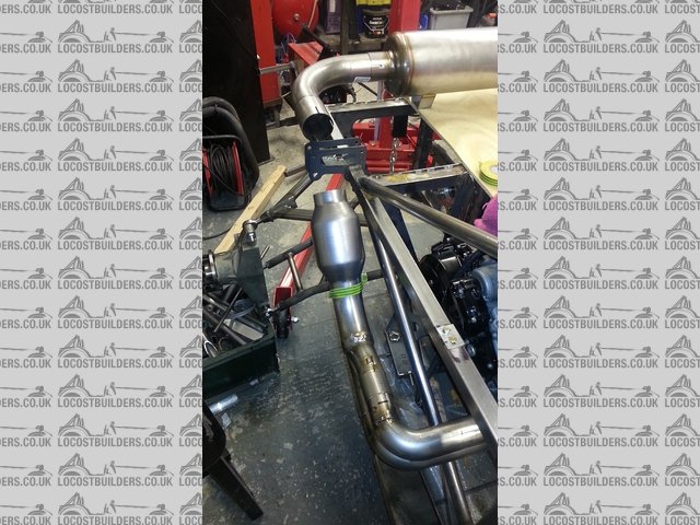
Description

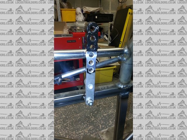
Description
Looking really good. Have you any interest in marketing this at all ?
short answer "maybe"
i'm a production engineer by trade so turning it into a makeable product is not a concern.
I would change several things, as after all this is a prototype to iron out the bugs.
I just have not decided it also depends on interest.
body will be very the main factor / I have several thoughts on this but not really worried until feb march time after mechanical finished.
so its a weight and see
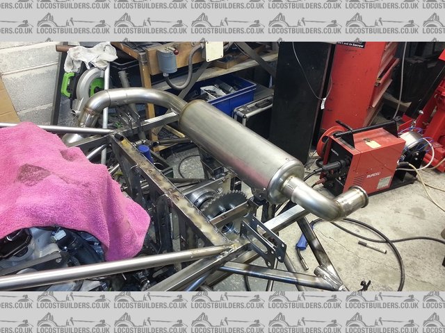
hi all
I almost finished the exhaust today
mounted the back box to chassis
altered the final exit pipe
and made some intermediate pipes.
mounting the back box to chassis

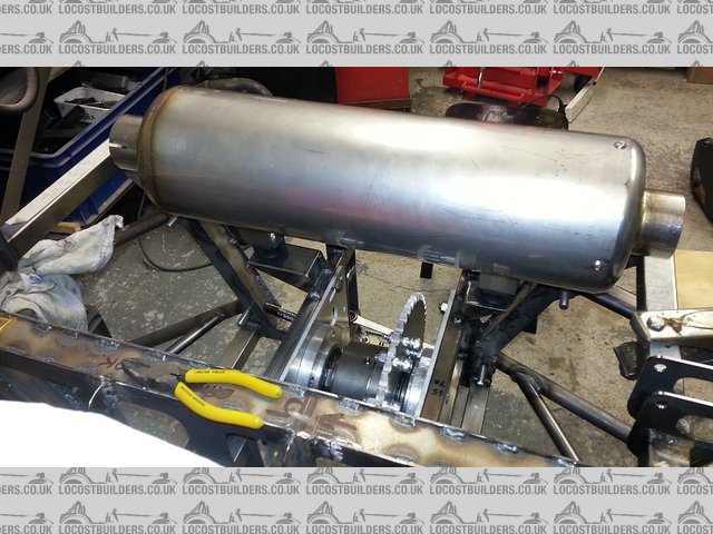
Description
new exit pipe

Description
rear view

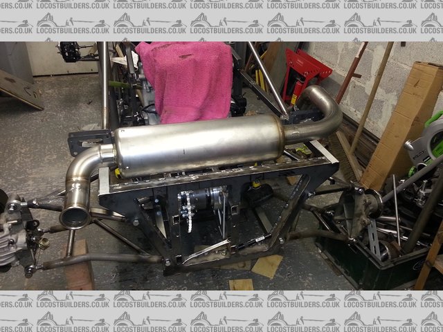
Description
intermediate pipes and cat

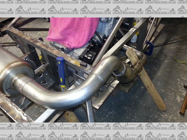
Description
That certainly is some exhausting work, I will be interested to see how you design the rear body around this
quote:
Originally posted by mark chandler
That certainly is some exhausting work, I will be interested to see how you design the rear body around this

only suggestion W.R.T. the chassis is the lack of support on the roll hoops, in my mind they'd want to bend in a roll, probably backwards.
The braces going back from the hoop are just from sort of a midpoint so could still bend enough to squish your head?
i dont know are you calculated steering rack position, but from photo looking not good. As far as I am familiar rack position, it are to far in front,
rods angle to big. Than you steer, wheel angles go wrong, unless you using anti ackerman?
found pdf, where more information about rack position
http://woodwardsteering.com/images/cat05%20pdf%2064-79.pdf
[Edited on 13/12/14 by fregis]
the steering rack is where the suspension program told me to put it , but reading up I get your point .
I will do some further investigation.
any experienced comments from anyone else ?
further today
spent the day working on the exhaust again.
and making engine spacers for position.
and had a good tidy up
now im back out to the garage see if I can move the rack !!!!
Few years ago i try simulate rack position in draw. Use typical ackerman, all start in zero TOE, steering rack turned same (70mm), but rack position
moved 2cm, 4 cm and 6 cm ( start point rods are straight position looking from top)
it is little messy, but i think you see how much change turning
http://images60.fotki.com/v367/photos/1/1313721/8097125/auksine2Copy-
vi.jpg
It is different if you are using anti ackerman, single seater sometime use this, this position wil be ok
as far as I've noticed about rack position - when it in front axle or behind axle, rods have different angle. Because upright steering arm have
different angle, so need different others angles. Sorry for terrible english, sometimes it is difficult to explain what I know 
[Edited on 14/12/14 by fregis]
well I have spent most of the night and morning following up the comments about the rack position.
and I have to say at this moment I am now in agreement .
luckily I have more than enough room to move it to a better position behind the rod end line.
a few comments in other posts all sort of point to mid way between the axel line and the steering arm end line.
for ford Cortina geometry front end.
I will do some calculations starting at this point and work my way forward.
I'm just glad it was brought up now as one of the next jobs was to fully weld the rack mounts.
still some good news I can now mount the battery where the rack was , I was wondering where to put that.
ho hum forward we go
anything else any one spots , only to glad to consider it .
hello all
well I have spent the last 48hrs reading every thing I could from every conceivable place about Ackermann steering.
my car was designed with anti Ackermann and since being prompted to have another look I have decided to go quasi Ackermann or at least as close as you
can get using a ford Cortina front set up.
the rack has to be moved back behind the rod to rod line and that is what I am planning to do.
as you can see in the picture I have removed the brackets from the original position and temporarily placed it in the approximate correct position for
minimum bump steer and best steering position.
just enough room to get it in ahead of the brake pedals.
means I wont be able to adjust the pedals for any one else over say 6ft 5" > 7" but I can live with that.
just have to figure out the best way to fabricate some solid brackets for the rack now.
having stared at it for an hour I decided to sleep on it and got deviated onto the gear change mechanism.
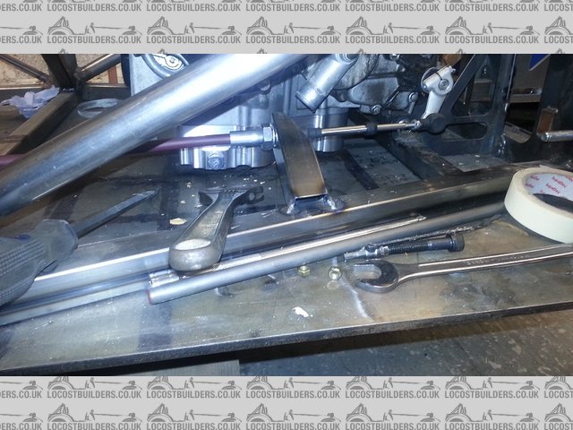
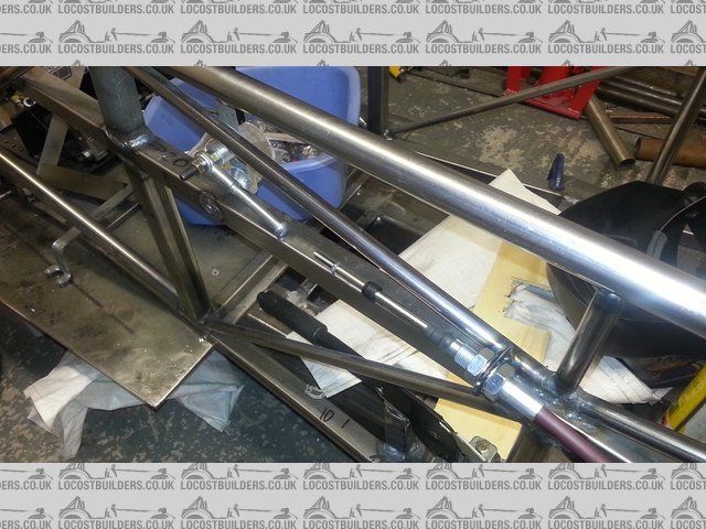
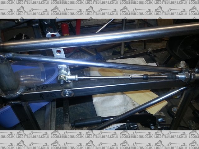
gear change cable arrived today so fabricated the holding brackets . just need to make an adapter for one end.

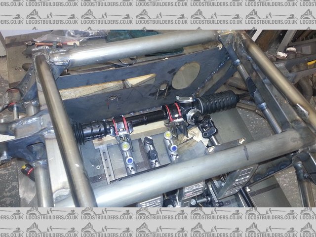
Description
gear change mech rear

Description
gear change mech front - the missing adapter ( another job on the list for xmas )

Description
[Edited on 16/12/14 by bart]
gear change finished

Description
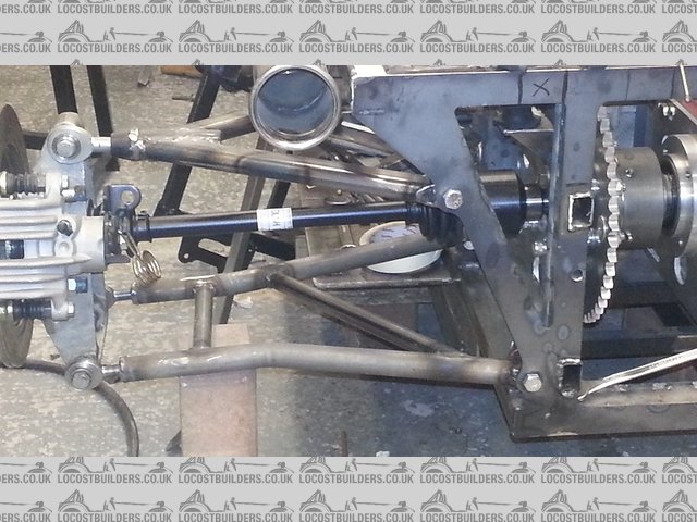
drive shafts arrived temp fitted.

Description
Looking good  - any reason for the stick shift over paddles?
James
re stick shift
good question
couple of reasons
1) this is very much a prototype , see if it handles ,stops , what's the chain drive like ect
I have already learnt a hell of a lot so far and would change many things. so gear change did not need to be so fancy at this stage
2) trying to keep the cost down
3) sitting in the car ( going broom broom ect ) stick shift felt quite natural and is right next to the steering wheel.
4) lack of room - the mid bulk head needs to be 30 to 50 mm further forward , whilst not impossible to get manual paddles in it would be a task as
is
5) that leaves electronic paddle change see ( 2 )
6) its something that could be added when the rest of the car has been proven .
and some more that elude me at present 

well today I finished my fuel tank all but two top mount brackets which I cant position till in the car
has an internal baffle
has a baffled bottom sump
a modified fuel sender that will work with bike clocks
1 bottom fed out let
1 in the top ( tube to bottom ) return
1 vent
and 1 inlet 1 1/2"

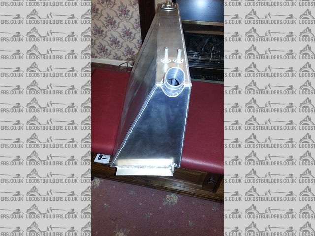
Description

Description

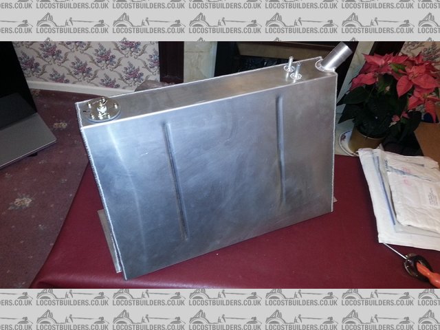
Description
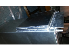

Description
sump
also been working on the reposition of the steering rack 80% done now , just needs some cross bracing and will be finished
have made provision for adjustment as well. leave's the steering links a bit iffy , but nothing is unsolvable I always say
pics to follow tomorrow if the wife don't make me go shopping .
my aim is to complete all chassis fabrication in the next 10 days and paint and put the floor in . we will see how it goes , I can see xmas day in the
garage although I have to cook xmas dinner .
Nice work that 
Good work Bart, nice to see you more into the car than Xmas.. wish I could be bothered to get on with mine!!!
Tank looks nice but... what's the point of the sump when the feed/outlet pipe isn't from the sump?
Also it there a baffle between sump and tank and why is the sump so shallow?
outlet is fed from sump just comes out higher up for good welding.and yes the sump has a top baffel with down pointing swaged holes to main tank .
also vertical baffel in main tank . total about 36 ltr
[Edited on 21/12/14 by bart]
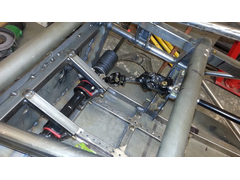
had a slow day but did finish the position of the rack
checked all the steering joint angles and they remain within the maximum stated.
need to add some cross braces still but happy with the outcome.
also checked clearance round pedals that's still workable as well.

Description

Description
Coming on nicely, i dont think i will get away with car building on christmas day!
hi all
did not do anything directly on the car today
ordered some bits to keep me going over xmas and did some planning.
went up to see my mate who lets me borrow his big lathe and milling machines when I need and did some
mods to a parting off tool I need to make the engine spacers on my small lathe
brought it as fits my myford lathe - total rot not with out some milling with some very hard teeth cutters - hey ho ! ebay !
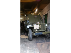
any way did some wiring mods to his 99% original willy's jeep , he now has a horn that works .
its a total pig to start being 6 volt , I've asked him to let me convert to 12v but he's having nothing of it . we will see when he has to
push start it.
he's just put a new steering box in , but it still brings a whole new meaning to vague steering ,---- sort of point and pray .
and the brakes are like old Harley Davidson brakes , I call then weekend brakes , you stamp on the pedal one weekend and eventually stop next week end
 .
.
his other car is a full race tuned porche gt2 ------- chalk and cheese !
no accounting of what goes through a petrol heads head eh !
ps: jeep sounds sweet when started runs smoother than a lot of modern cars !!!!!

Description
well first the good news
my modification to my new parting off tool works a treat.
now the bad news
I cant get the feed from my steering column anywhere near correct , thought I had , but it was B------s " total B-------s.
loads of solutions all C--p , or put me back 2 months.
1) make a new chassis 150 mm longer maybe even 200 mm longer
2) have new uprights made !!
3) there's a small possibility that new design steering arms might do it
4) burn the fin garage down !!
rant over , i'm going to have a hot bath and some thing to eat , just might be I cant see the wood for the trees ."I hope"
What's the problem with the column/rack exactly? The column won't mate to the rack? My main question would be why you are using a handed
rack on a single seater? Building a single seater means you can use a made to measure Titan rack or one of the many off the shelf single seater
racks.
One of my little projects to make a converter plate so that the steering arm is on the top of a Cortina Geo' Rally Design upright so the rack and
column don't interfere with the pedal box.
its all to do with the low height of the rack. and to get clearance of the column over feat ( size 12 ) it has in its present configuration
got to take a dramatic dive down to the rack and as you say with the offset escort rack its made worse , a central rack may help its something I had
already thought about.
one of the "solutions" is to use the left hand arm on the right hand side and visa versa
this will enable the rack track ends to act above the arm not below
this adds about 75 mm ish to the height of the rack from the floor this may help I need to play more tomorrow
this does improve the geometry of the steering as well . the only problem is it leaves the disk to close to the track rod end ( heat )
looked at moving the disk that's a no go with the calliper mount will only get 3mm at most.
as I said maybe some custom steering arms are the answer , just need to think it through.
I have tried to post every process to show the kind of thought's that we all go through with problems
maybe I should keep some things to myself , I was really just letting off steam
I did also consider using a clutch on the gear lever but have thought better of it. this would have meant I could use a left hand steering rack.
I might leave it for a couple of days and come back to it . sometimes the best solution , to find a solution
[Edited on 23/12/14 by bart]
quote:
Originally posted by bart
Description


Damn right, I want one!!!!
On a V6 Caterham I was building, the headers interfered with ALL column routes, so the column went over the top of the headers to the front of the
chassis and into a 90 degree steering coupling. It was a milled aluminium block of two halves with a splined input shaft on 2 faces with internal
gears, and then through a short shaft to the rack that was rotated slightly.
This could be a simple solution for you?
Apologies, but I can't find details of it at the moment, but a call to Russell of RS Performance (the people who build the SC V6 and V8 Levante,
Caterham's) will give you the answer as he had to fit them on all of his cars...
quote:
Originally posted by bart
well first the good news
my modification to my new parting off tool works a treat.
now the bad news
I cant get the feed from my steering column anywhere near correct , thought I had , but it was B------s " total B-------s.
loads of solutions all C--p , or put me back 2 months.
1) make a new chassis 150 mm longer maybe even 200 mm longer
2) have new uprights made !!
3) there's a small possibility that new design steering arms might do it
4) burn the fin garage down !!
rant over , i'm going to have a hot bath and some thing to eat , just might be I cant see the wood for the trees ."I hope"
looks like rs performance have gone under
but now you have given me an idea to look for ! thanks Steve
Also have you looked at double cardan joints from woodward? Will need bearing support on the lower steering shaft, but will give up to 64 degrees of
angle and if you split the angle correctly, very little variable velocity associated with high angle UJs
James
thanks every one . im close to a solution now.
just needed tea . more tea . and a clear head . oh and several attempts. I had looked at double jionts and I already have a bearing support so I
might use one if I cant get the last bit..
just considering moving the rack 10mm off ctr and resticting one side. don't need all the travel on the rack. Any way. so loosing 20mm is no big
deal.
as I say just thinking through implications.
yep going to need a Woodward double joint
any one brought one in the uk
I will post a separate request on the forum as well ketch a wider audience
hi all
well sorry ive been quite its been all about my steering problem
tried thinking about all sorts just could not find a solution , inc new custom rack and as a last resort I was really considering a longer chassis.
any how ! I do have a solution
the plan
1) use a lhd rack
2) split up the pedal box clutch mounted over to the left and accelerator and brake mounted over to the right ( its not that far apart extra 60 mm
steering column will now run down between the clutch and brake , making for a good angle feed, means there will be no quick access between clutch and
brake , but its nit impossible just awkward .
so unless anyone can think of a reason not to do it then that's the plan as soon as rally design are open or someone sells me a steering lhd rack
I've read a few books on single sweaters and a few have that same solution with the split pedal box, and I can't think of many reasons you'd want to have access between clutch and brake.
well hello
ill post some pictures tomorrow as every thing is half way through.
split my brake pedal assembly up and added a new re-enforcement bar to the clutch
then proceeded to chop out the floor in the front of the chassis to be ready for a new adjustment floor ( piece of 4mm plate  )
)
and have sussed a much better way of rack adjustment when I install the lh rack . this will also allow easier installation and better adjustment of
the pedals.
as I say pics to follow.
in between waiting for paint to dry started to final assembly front uprights. found that one of the installed wire inserts in the ally is at about 85
deg not 90 and its F----d , so that's going back to hi spec Monday if they are open, could rework it but don't see why I should.
ps: never did like my pedal adjustment frame - so good riddance to it I say .LOL.
hi all
progress in preparing for left hand steering rack
picture of old front floor with brake box adjustment this has now been totally removed


Description
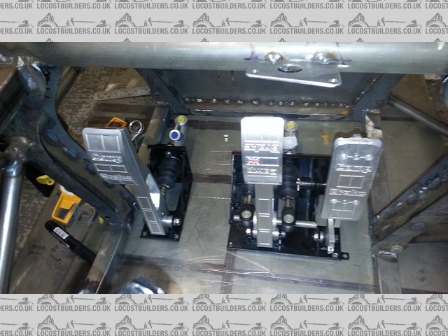
this is a picture of the brake box that has been split up and refabricated to allow the steering shaft to travel between the clutch and brake.
I think the clutch is now a little lonely !

Description
and the new design for the left hand steering column
it is now fitted for vertical mounting and can adjust up and down and back and forward via shims
when I shorten the steering column I will change the brackets to allow for vertical clamping
picture shows the front bulk head which needs modifying but this can be done when I fettle the frame for spraying ( soon I hope )

Description
tomorrow's plan is order rack and front floor panel , and finish the engine mounts.
Hi all
well I thought this afternoons effort was going to be boring and was not going to post any pics but it all turned out different.
it was ""fin" cold in the garage today so I put the heater on and left it for a few hours and went and ordered the bits I needed.
when I went out I could only work with the heater pointing at me ( yes I know i'm soft )
started out making the rear brake spacers ( instead of packing washers ) and then made the spacers for the engine brackets
all very boring so I did not take any pics , I was thinking about going in about 5 pm for me dinner and was drinking a good brew contemplating what to
do next whilst waiting for bits to arrive , decide that I needed to fit the electric reverse. so got it out the box and started to have a good
look.
first I had to take the sprocket nut off and speedo sensor nut ( more on that later )
so I knocked up a sprocket holder with some old chain that I had liberated from a mate . made the job of undoing the nut easy ( well a 36mm socket and
a 4 foot power bar )
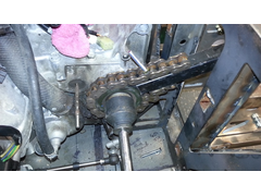

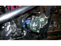
Description
sprocket holder easy peasy job now
I then fitted the reverse drive cog instead of the nut and tried several positions with the reverse electric starter.
having found a suitable position ( let me clarify that , I spent 30mins deliberating where to place it to allow for chain adjustment , it then dawned
on me the engine dose not move only the diff does " i'm an idiot " so no need to allow for movement only a small swing movement for
cog engagement) . ps i'm blaming the senior moment on lack of food.
I decided it will only take me a few minutes to make some brackets to hold it in place , and for once I was nearly correct within the hour ( ok ok ok
it was close ! ) I was finished , needs some better brackets but all seems to work well.
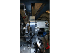

Description
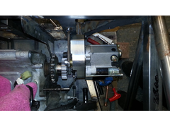

Description

Description
few things I need to check , I am going to fit a dry sump so need to check oil pump and clutch cylinder
call to extreme engines tomorrow if they are back .
and then make top engine mounts . then its reflection time
Had any thoughts on where to put the handbrake lever?
hi cloudy
fitted it down the side of the seat with the grab handle sticking out the front of the seat
I think there's loads more pics round about page 2 and 3


Description
it about only one of the systems that I can say is 99% cast in stone
every thing else remains flexible
I don't weld anything fully now I can do that last before chassis paint .
going to mount the ignition key down the right hand side of the seat . I think
whilst i'm posting , front part of the aluminium floor 4mm just arrived so I know what i'm doing tomorrow
also took the plunge and ordered the dry sump system. bank account now empty
going to have to find some sub contract work in the new year !
Must have missed that! Reckon you'll have enough elbow room to give it a good pull?
yeh I have tried it no problem . 
What is the front handbrake cable off Bart? Looks MX5 but a bit shorter?
Subaru impreza ( hand brake front cable that is )
brought a whole damaged car and stripped it
still got engine and gearbox to sell and lots of other bits
?????????? any one interested ????????
[Edited on 30/12/14 by bart]
hello all , and happy new year
well dawn broke and the tnt man arrived.
the titan dry sump kit oh yeh !----- quick hide the receipt before the wife sees it !
had a cup o tea and a good rummage through the box . then out to the garage .
spent a lot of time today in a small area
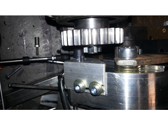
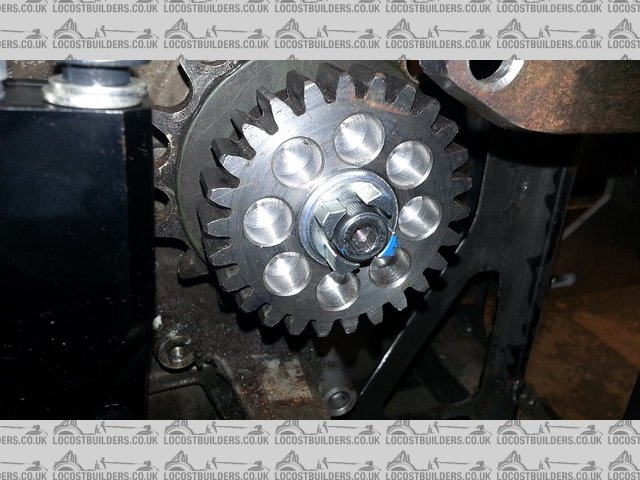
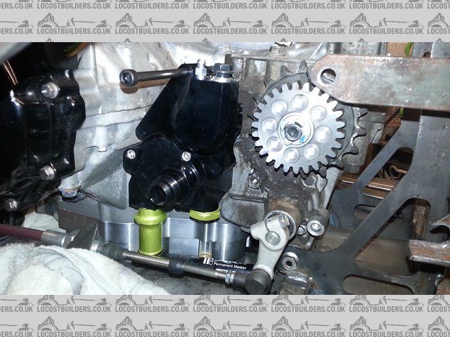
first I modified the brackets for the reverse starter and wired it up temp to see if all works , another small adjustment then all ok.
second modified the cog that replaces the lock nut on output shaft for reverse so as to do away with the spacer .
then decided that I would temp fit the dry sump pump and slave clutch to see if all fits ok
"yes" all fits ok , titan dry sump looks good and should be easy to fit
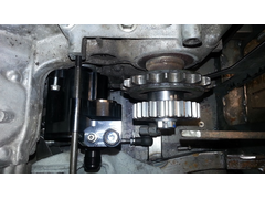
then decided to alter the cog again so that I could retain the original Suzuki speedo counter
as per pics did this and made a small alloy bracket for pulse counter , that bolts to the reverse counter.
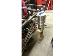
then had a play with position of dry sump tank , its going outside the frame in the side pods
then to finish decided I best start thinking seriously where the rad will go , so there is a pic of suggested rad position.
I will not be using the original rad but it was just to get ideas.
todays pics in no particular order.

Description

Description

Description

Description

Description

Description
if any info on dry sump needed just ask and I shall do my best to inform 
hello all
LH steering rack arrived today
stripped it ready for shortening , a bit of deja vu as I have done this before on the rh rack
ps new rh escort HD 2.4 quick ratio rack for sale been shortened by 100 mm exactly and done properly by machining
with brackets
£ 150 sound fair u2u me if interested
lh deja vu

Description
the rest of the pics today are just layout tries

Description
side view of sump tank and oil rad

Description
rear
this is all starting to give me body ideas ! now
the last pic shows second try at radiator placement , card in the pic is the size of the small polo rad , going to go for wider by 50mm polo rad as it
will be less shrouded by air box . works out quite good means the back of the car will have a wide tunnel f1 style

Description
[Edited on 2/1/15 by bart]
quote:
Originally posted by bart
hello all,
the last pic shows second try at radiator placement , card in the pic is the size of the small polo rad , going to go for wider by 50mm polo rad as it will be less shrouded by air box . works out quite good means the back of the car will have a wide tunnel f1 style
[Edited on 2/1/15 by bart]
looks good steve.
re body thoughts
there are some givens
1) must be road legal
2) must be modern looking or even radical ( design that is )
3) must cover all the bits ie : exhaust , oil tank , side mounted electrical on side of driver area
4) be a aero dynamic , and potential for down force if required.
thought !! if I make the car enclosed it makes getting in and out very difficult ( instead of " its a long way to the top" - its more of its
a long way to the middle ! ) so I think the car must tapper to the middle but this makes it very un aero dynamic I believe.
going to the auto show next week might get some inspiration
and so :
thinking so far
1) could go fully enclosed ie: radical / spire ect
2) rear enclosed front cycle wings
3) enclosed body out to cycle wings back and front
so that's my thoughts so far
all suggestion's will be digested and taken note of

hi all
well today was a busy day
first I stripped the bits out of the chassis ie: engine diff ect ect
took chassis out side , then took my build fixture table outside , painted it to stop rust and left it there to dry , I suspect it will take weeks due
to the temperature.
had a good clean up and put the chassis back in on stands
fitted the petrol tank for the first time , due to it having to be loaded from underneath . " it fits" that's a relief .
fitted the tank suspension units and decided on another clamp required at the top of the tank , I had already suspected this its was just conformation
, will weld the brackets on tomorrow . also have a mod to breather on engine to weld up.
off to machine the LH rack tomorrow . oh ! and I have run out of m6 nuts LOL
plenty to do this week
dry sump the engine
uprate clutch ect ect .
some pictures of the tank in situ

Description

Description
more pics to follow tomorrow , it been a long day and i'm off to soak in a hot bath .
ps offer : if any one wants to borrow a decent fab table u2u me . its flat and 3 mtr long
looking good
hi all
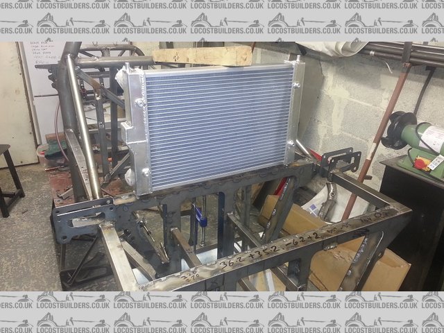
ally rad I ordered arrived today
its a polo rad but slightly longer than 1.0 ltr job , considering where its going I thought that the extra width would get me out of the engine shadow
some what . it all going to be ducted any way.
shown not quite in position as it will be 50mm further forward and 50mm down.
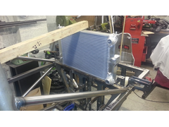

Description

Description
finished shortening the LH rack today , reassembled and trail fitted , mad the steering column and I am now happy with the result .
all angles under 20 deg and I also fitted the collapsible part of a ford ka column for safety and IVA .
need to make some rack spacers and finish welding but all should now be plane sailing . ( famous last words )
also fitted the modified dry sump tank , and the modified fuel tank brackets , sorry no pics I forgot.

Description

Description
finally shot showing collapsible part

Description
hi all ,bit of a revelation day
got the steering rack spacer made , checked length of front coil over required, then decided to drop the chassis down to the correct level off the
floor , ( first time )
wow what a difference , bit of a revelation feels totally different , feel happier that the body work that is forming in my mind will work and fit ,
total confidence boost
picture does not do it justice .
" full steam ahead captain "

Description
Looking good keep up the good work.
hello all
no post for a little while , I went to the auto sport show ( same as last year ! ) and then spent a couple of days thinking about the body ( did a
few small jobs nothing to shout about )
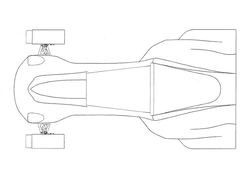
I started off thinking that I was going to enclose the whole rear end in a moulding bit like the back end of a squire or similar
here is one of the sketches I did to play with that idea.
I think it would look unbalanced if I did not enclose the front as well , also that posses problems getting in , and I just don't like the whole
body enclosed . enough said , also think "bat mobile" or flying dick !

Description
so Monday I dropped that idea and went to a single seater formula type thing . so ill end up with cycle wings and side pods.
here are some pics of my first mock up to get a feel off things

Description
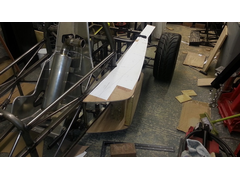

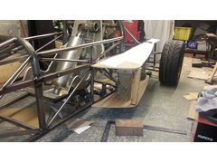
Description
no where near settled but food for thought , all comments accepted
I have also moved the exhaust to the left hand pod with a side exit exhaust
and moved the rad to the front of the car ( lower back and better cooling )

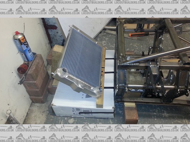
Description
I haver also finished position for front floor and the front floor / brake plate.
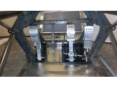

Description
why start body now I hear you say !
the reason I have started body design is it will allow me to finish the chassis and floor ect, so I know where my mounting points will be and so on
also position minor stuff like dry sump tank header ect .
also finished my seat belt installation , have a four point in the car at the moment but have put bosses in for five point if (I can loose enough
weight 
I quite like your first sketch to be honest and i think you would get away with it as its a single seater similar to the caparo t1.
hi all
more side pod action
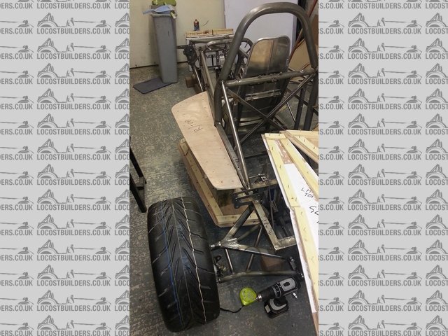
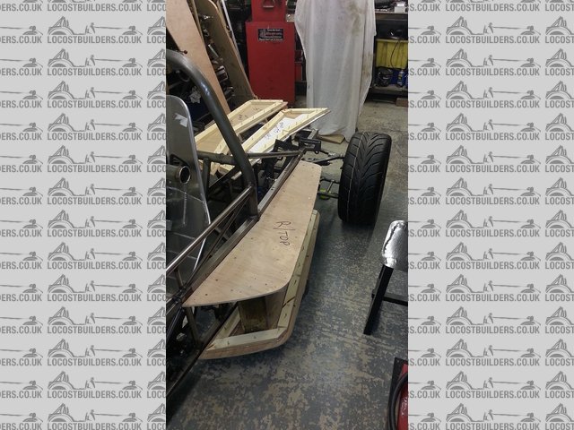
started to make the side pods in Ernest today , made a LH and a RH frame that will take foam when finished for further shaping
when both fitted it looks quite balanced front to back and front to rear , I am pleased so far , still welcome comments.

Description

Description
[Edited on 15/1/15 by bart]
hello all
further progress with side pods ,
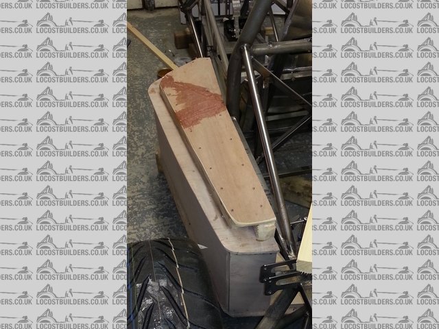
as you can see the lh ( looking from front of car , I know don't say ) is not as advanced as the rh , mainly cause I ran out of steam  . will
need to add foam for radii ect when both finished .
I have been having a good think and spent many hours playing with ideas for the rear end , and I am nearly there ref knowing what I am going to do .
going I think with fixed fenders , having the side pods helps a lot. garage looks like a wood yard , daren't weld anything !

Description

Description

Description
as I say above lh not as advanced as the rh.
should get them to the same state tomorrow , but and its a big but , tax return needs doing , keep putting it off but it has to be done !
hi all
brought the lh side pod up to the same level as the rh , and started to play with the rear deck height and shape
the wheel in the pic is above its normal top level so this would be where the wheel arch sits. early days yet but playing around helps form ideas ,
contemplating moulding the whole back end in one piece . might be to much and difficult to lift off , could hinge it ! so many considerations 

Description
Never get bored looking at your progress pics. Keep them coming. Makes me what to build one.
hi all
been a bit quite I know , but lots of thinking going on.
i'm pretty much happy with the side pods , (I need to wait for warmer weather to progress )
so have moved on to giving serious thought to the rear engine cover and rear wheel guards / arches
I have been drawing up in solid works cad , now all the work I have overdone in solid works has been using solids , and never used surface modelling (
just never needed to in my line of engineering ) so in order to progress with body design i'm having to rapidly teach myself surface modelling ,
so its slow progress as far for end results
but i'm starting to get to grips with it now
below is a pic of my efforts so far by know means finished ( about 95% to go id say ) but we all have to start somewhere

Description
[Edited on 23/1/15 by bart]
further rear thoughts , not sure if I like it , may dump this idea and try again
still here is a pic
Description
I would make the rear arches seperate to the tub to break it up.
hi further progress
as per past suggestion ( although I was already sort of going there )
separate wheel arches at the back
still work in progress
starting on the front "bonnet" and pointy bit so I can see it all blending into one harmonious look 
Description
Looking good - for a first stab at solidworks surfacing that's mighty impressive! (Solidworks makes that job very tricky!) 
James
thanks for the encouragement
its been hard word as you know cloudy
sort of goes like this " ahhh the joys of surface modelling !
tea
try
tea
try
you tube
try
tea
tea
more tea
try
have a kip ! ( brain hurting )
tea
try
you tube
Google search
try
tea
limited success, model crash , try again
it helps a little that I have reasonable solid modelling skills, but as you know "surfacing " is almost totally different .
lost count of the number of solid works crashes . but I do save different versions regularly so I can always go back
ect ect ect , so on and so on
any way time for a brew !
anybody have a 3 axis cnc router worth an ask ?

moving forward
latest direction , still learning
front nose cone needs to be longer , job for tomorrow
also the front top cover needs more shape Mañana
Description
Description
[Edited on 30/1/15 by bart]
Looking good - would a convex curve to the top of the nose work better?
further progress
the number plate is built into the front nose
side view looks like a shark so thinking I am going to call the car the ****** isurus which is a very large extinct shark of the mako family I
believe.
still not finished but getting there
need to add side pods redo rear panel
alter top rear panel
make cot pit cowl , and a few more bits
then I need to start building the bucks and moulds
never done that before so should be fun !!!! need warmer weather though .
just got to decide how to make the shapes , pay for full 3 axis cnc foam milling or cnc skeleton and fill in with foam
side panels I think will be made from ply wood I think not sure on others
still lots of design work to do .
Description
Description
shark !! ?????? or am I just seeing things ?
Description
Looking good mate!
hi all been messing around with small detail today drew up the side pods
there not supper accurate but near enough
need to make them thinner to balance the car , but there's a lot to get in
radiator , oil rad , dry sump tank so its going to be a challenge .
sometimes I stand back and think " WHAT HAVE I TAKEN ON" but hey ho on we go 1
Description
hi again
just getting ready for sunday night , top gear , guy martin , then dragon's den on I player
Sunday nights are watchable again.
any way thought id post a picture of the nose cone , shows built in number plate
FYI , it wont be red I don't think , just easier to model in red , shows all the bumps and dips ( depressing some times )
Description
What's the purpose of the pods?
For me it would have curved sides aka brapham BT33 or similar
In answer to side pods why
Radiator
Part of the exhaust , mainly the cat
Oil rad
Battery
7" * 18" high dry sump tank
If I can find a way of getting that lot in without the pods then I totally agree I don't like them either. So big think time
thought id post a see through view showing rad and dry sump tank
Description
Looking good - is it a legality to have the number plate standing proud or could you recess it which would look much better.
On my Cobra for instance the number plate is set about one foot back from the mouth of the air intake and high under the nose on the radiator so it is
only really visible if you crouch down - at the time of registering it the law said it had to be visible from the front, not at what eye height. 
[Edited on 2/2/15 by Ivan]
I'm speaking as an armchair bodywork designer here LOL, But do you think it would be possible to make the nose area wider, deeper and higher to
balance out the bulk of the back end ? It looks really good but the propotions seem out to me. As always though great work.
[Edited on 2/2/15 by wylliezx9r]
How about designing the number plate bit so it acts as a dam for the future splitter?
hmmmmm ! hmmmmm hmmmmmm
whilst having dinner I looked into number plate viewing angles , law not that clear,
I suspect Mr plod might take a view as well , not sure what they could charge you with , but I bet they can think of something.
one part of the regs mentions visible to automatic number plate recognition . so there's probably a very wide interpretation.
still > I have dropped it 10 mm pulled it back 10mm and that as far as I think it should go.
reference "looking dumpy" yes I agree I have made the nose 40mm "less wide" and altered the side pods and its looking much smaller
, also in the view posted I had perspective turned of so it looked worse than it is ( foreshortened )
working later on cockpit infill so that will also make it all look better .
will post some pics later tonight if all goes well.
looking better , ! well slightly
Description
hi all
nice day so spent the afternoon outside
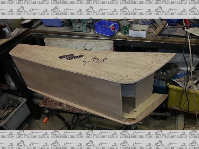
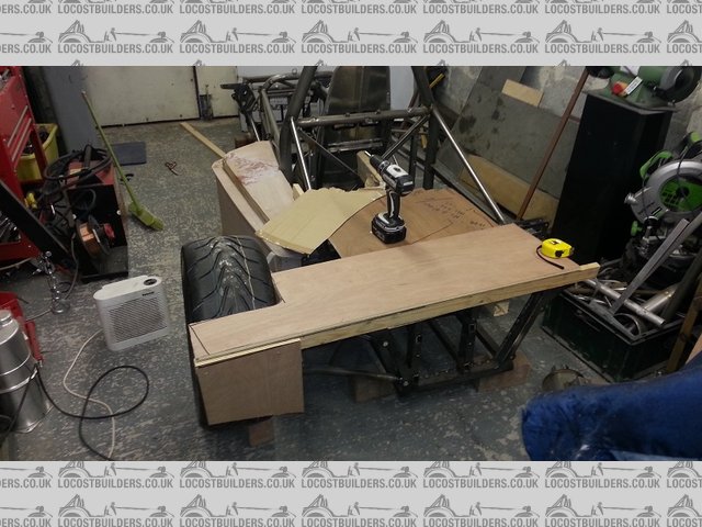
cut down the side pods to a more balanced size , they look much better in the real world now
will look to finish these soon.
should be fun never made a fibre glass mould before .
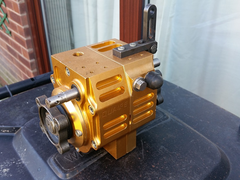
also In case any one misses it I have a never run Quaife reverse box for sale

Description

Description
full description will be in the for sale section
further getting there
number plate say's it all
Description
It is getting there.
My tip would be to print on paper the main views (front, side, rear, top and ortho 3D) and sketch with pencil/ paper over it. Another useful exercise
is to draw the wire model lines on it.
This will enable you to translate your ideas better to a3D model.
Enjoy!
feeling blue !
with rear lights and a few small mods
bit busy with work at the moment so not much work happening
Description
Description
Description
Description
Liking the blue 
To my eye from above nose looking a bit shovel-like due to the "waist" around the driver - how about increasing the width here and use the
space between the chassis and body for a honeycomb side impact structure?
James
mmm cloudy !
side impact .
I have already given some thought to that.
due to the chassis structure there is considerably more protection than say a seven type , and I believe the side pods which have a steel frame inside
will add a little . i've looked at the wasted side problem myself got to say i'm not 100% happy with it. might give it further thought.
have to bare in mind one needs ( one sounds very royal ) to get in and out easily , I did think of the pods going down the body a lot further but then
you would need 6ft legs to get in. still thanks for the feed back all comments / thoughts welcome , sometimes makes me think again or stimulates
another idea .
added the rear wings not quite finished but gives the idea
trying to find something appropriate but cant looks like ill have to make those as well
any one know where to get 15" wide flat wings quite long
added rear number plate light and altered the lights to comply with iva angle view rules
Description
front wings will be identical but nut so wide wont bother drawing them
carbon mods do anything suitable?
easy enough to mould your own - especially as you are doing the body too..
Thinking of doing wings first as a test
Carbon mods don't do wings any more according to there Web site
you are right... 
hi all
no picture tonight as I have only been doing cad work and to the eye there not a lot of difference to the last post. just minor design change , takes
time but not a lot to show.
I have had some prices for 3d 5 axis milling ,and that's put that to bed , its far to expensive ( £500 just for nose cone ) so it looks like its
going to be 3 d skeleton and foam infill and lots of glue , filler , sanding and swearing  .
.
have decide to make the moulds combined > front nose cone and front top together .Then 2 sides in one fixture / buck as the middle portion would
be symmetrical . I will post a picture of that one but it looks good in my head ! and the rear top and rear panel together.
other reasons for this is the join lines are common and it saves having to try and match moulds .
I will keep you all informed with pictures as I design the mould skeletons .
so going to try and get 3 to 4 hours on it tonight lets see where I get to .
im going to build the moulds in order to copy slit lines as well
front cone
front top
side left side right
rear top
rear back
also on top of these I will be doing the side pods and 2 wing bucks
and a cock pit / dash board surround last.
I recon 3 days the lot !!!!! 
3 weeks you mean ?! 
3 to 4 months minimum I recon ( was just a wind up before , just checking any one was reading ! LOL )
you have to wait 2-3 weeks for the moulds to go off before you can take a moulding or so I have read ! ( east coast fibreglass )
which will stop me making the next mould in the sequence .
in truth I recon 4-5 months due to work to pay the bills as well , and i'm old and n- - - - - erd 
mind is willing body gives up after about 4 hours
the other problem is physical space recon I can only make one big combined mould at a time. and there's 3 big ones 5 medium
and the mess , going to have to sheet the rest of the garage off .
last problem is temperature all the materials i'm looking at are minimum 18 deg c . so winter is out which means no laminating of moulds or
parts till at least April ( with a heater ) they say must be at 18 deg + for 24 hrs so I don't fancy trying to do ambient +20 deg for 24hrs ,
much rather try say 12 deg ambient boosted up to 20 deg with a couple of say oil filled rads , don't fancy leaving cheap ass fan heaters on when
i'm not there .
if any one knows different then i'm all ears
I recon 2 more weeks mould ribs design ( i'm busy with paying work as well )
2 weeks for 2d cnc routing
then start mould manufacture from there .
started on front mould design tonight
extended all the mating surfaces of the fibre glass to allow run off and will now finish 90 deg lips to make the mould stiff
Description
ps: also the moulding ( optimold ) resin goes off after 6 weeks so have to plan quite carefully so I don't waste loads of material
pps is it MOLD or MOULD seams to be spelt to ways depending where you look ?
Not sure about optimould - but easycomposites' Uni Mould (very similar) is good to go after 24 hours. It's an exotherm reaction that gets
mould temps over 50c that actually does the intial cure (after about an hour). I then post cure ramp up to 90c for epoxy infusion work..
James
hi cloudy like you have done extensive research into both systems , it would appear its probably the same stuff with different labels on. ( expect
angry reply's ! )
the biggest problem seams to be getting all the styrene out after layup. force cure being the ultimate solution.
I spoke at length to the tech guy at east coast and he said that you don't have to use ie: 90 deg but if you half the temp you need to double or
triple the time , hence there web site saying leave at ambient for 2 weeks , this applies to there high temp styrene based resins for parts as well .
was considering making a big temp box oven from 100mm thick insulated roof board. and running it up to say 50-60 deg
for parts I may use epoxy resin in some instances due to the much higher heat property's ie side pods and rear panels
it would be wet lay , don't think I have the inclination to do pre preg but I could be talked into it
what due you use , epoxy , styrene based , pre preg ????
and do you use pva release or one of these more fancy chemicals
totally worried about these words that several people have said
"no matter what you do , you will get a mould that sticks to the buck and wont release , it happens to every one at least once"
18mm MDF box sized to your largest part, a PID temp controller & SSR relay kit from ebay £10, a £10 argos fan heater and lined with some foil
faced 20mm loft insulation boards will get you to 90c (the safety cutout on the fan heater prevents it getting much hotter) all in cost £60.
I use vacuum assisted resin infusion with epoxy resins (carbon/kevlar fibres) The infusion process is quite capable of better parts than prepeg and
much cheaper materials.
PVA + chemical release on all moulds (chemical can let you down on less than perfect surfaces) With PVA if the mould sticks, just get enough of a gap
to get a water supply in there, 30mins of soaking will get pretty much anything off a buck assuming you haven't miscalculated your draft
angles
If you want to do any epoxy you'll need to post cure your moulds - In my experience an ambient cure isn't sufficient no matter how long you
leave it.
Check out the easycomposites video tutorials - they're pretty good
James
thanks cloudy
If cnc machining is out of the question due to cost have you thought about slicing your solid model into 10mm sections and having them all
routed/waterjet cut out of a suitable foam... A lot lower tech so should not cost silly money... stick them together and then sand/fill etc to the
finished size?
[Edited on 12/2/15 by tegwin]
Hi Bart
I don't know if you have seen my log already
here
but if not you might find some of my experience usefull
Cheers
Fred W B
hi all
have not posted for a while , been very busy paying the bills.
managed to get several hours late last night designing the front buck for fibre glass fixture ( 2:30 am finish !  )
)
its not quite finished but close
hope to do the back over the weekend
Description
Description
Nice - lots of cut with surface? Are you going to "jigsaw" the formers to slot together?
[Edited on 20/2/15 by cloudy]
hi cloudy
yep going to use 3mm Foamex sign board , 2 ways to proceed
1) get the parts printed out on A0 paper and the stick down and cut out with model knife
2) get the parts cnc routed ( I would like to do this but need to get quote first )
as for slotting yes it all needs slotting was going to sit here tonight and try figure the best way to slot it all together.
its a bit of a problem as the model is top and bottom if that makes sense , still nothing a big brew , and a penguin wont solve !
( I bet that has the non uk visitors guessing what how a "penguin" helps ) ( and what a big brew is ) . 
miss bart ( no not lisa ,that would be incest ! ) is watching happy enders so that gives me some free time .
[Edited on 20/2/15 by bart]
HI all
still busy in work so brew / penguin and another very late night early morning
made a good start at the rear foam mould
should finish tomorrow night.
decided to plot the drawing out and cut the foam by hand
just brought a terrific bargain off eBay 3 year old hp 510 plotter for £310 with little use ( was listed in the wrong place ! )
says its working we will see when I pic it up
I needed one for work anyway , so two birds with one stone
Description
hi all
went to Chester today to pick up my new 42" plotter
well well well pleased ,what a barging , got £150 of new cartridges with it , there's not a scratch on it looks like new.
first true bargain I have had of flea bay.
ps: it enormous the wife is so pleased that its in the dinning room / office.
can do up to 42" wide by any length you want , so I can print out all the foam former parts to scale to cut out.
ordered some rolls of paper for tomorrow , tried A3 the biggest I had and it works a treat

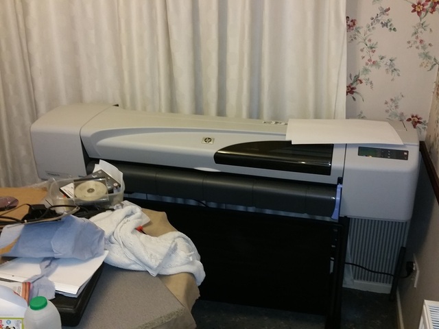
Description


result 
hi again all
finished playing with my new toy back to design !
finished the rear top part
just the rear lower panel to do
then I have to out put all the files so I can print them out
I will order the foam tomorrow and some spray mount glue recon I need 4 off 8*4ft sheets
not cheap but I recon safer than working with mdf especially with all the sanding .
posting all the detail pics so people can see how I am attempting to complete my build , I'm sure its not the only way but that's the way I
have chosen.
Description
Description

hi all some progress
went to Preston today to pick up some polyurethane roof insulation
got a whole Citroen Picasso full ( with all seats out ) could not have got a mouse in extra !
cost me £60 cash , worked out the same amount from some of the glass fibre places would have been £400
did some trials last week works a treat , easy to sand ,light weight , resin proof ,
also the pvc sheets arrived for the skeleton.
got most of the formers printed out , some more to do and I need to get some mdf for base's.
lots of work to do but getting there. slowly

Description

Description
hi all body work progress
1) finished design of rear and front body work
2) printed out full scale templates on my new plotter
3) stuck the templates to Foamex plastic sheet
4) cut the mould buck formers out with a Stanley knife ( on the lounge floor ! )
5) made the mdf support structure
6) assembled and glued the formers to the support structure
hard work but progress
random selection of pics during build
inserting foam starts tomorrow
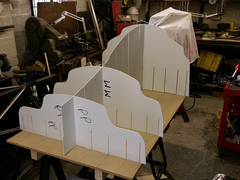

Description

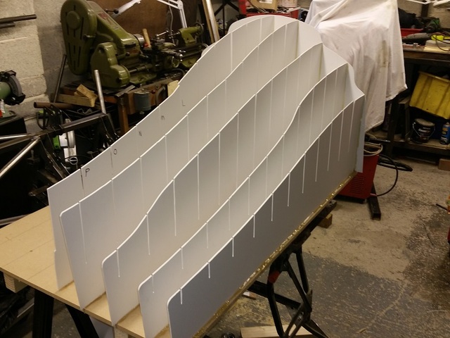
Description
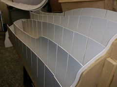

Description

Description

Description
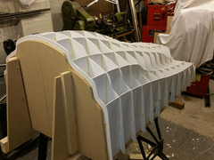

Description
ps: hot glue does a very good job of removing finger prints and any other skin !!!!
[Edited on 7/3/15 by bart]
further information
the skeleton is surprisingly rigid and strong , and will improve when I put the foam in tomorrow .
its hard work but far cheaper than cnc milling , will just have to see what results I get .
next week if I get time ill sand it down to shape and also I have to design the wheel arches and rear suspension covers.
will have to see if I can get the time in-between work .
this is going to take ages !
5 hours to do about 20% of the foam infill's
and using hot glue sticks at an alarming and costly rate
well I have started so I suppose ill have to finish
next job tonight order more glue sticks

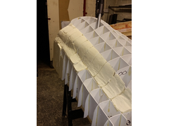

Description
cant believe how long this takes 40% done 
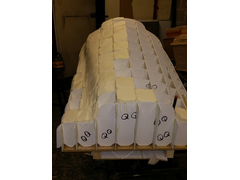

Description
Coming on nicely mate
Coming on.. If you think that takes along time just wait untill you get to the surfacing 
I cheated and had my blocks cut by a foam supplier.
Get all the foam in before you try to shape it. Try creep up to the profile by sanding the foam rather than cutting chunks off. It looks like you
already a bit low in some places. To do the negative curves maks some sanding blocks out of round wood stock or something
Cheers
Fred W B
[Edited on 11/3/15 by Fred W B]
[Edited on 11/3/15 by Fred W B]
[Edited on 11/3/15 by Fred W B]
hi all
hard work , boring , hard work , boring , body work oh body work
starting to make progress with the rear engine cover
all foamed up and starting to sand to shape
and YES I know some of the parts are below where they should be , well spotted !
" that's what body filler is for LOL" 
been a bit over enthusiastic in some places .
problem's to report for those thinking of doing something similar.
1) don't get hot melt glue on the outside faces , cant be sanded
2) try to avoid negative radii especially with compound curves
3) take your time don't rush like I did !
4) if I did this again ( which I wont !) then I would pay the extra and get it cnc machines , will work out cheaper in the long run.
5) top tip . if possible get someone else to do it !!!
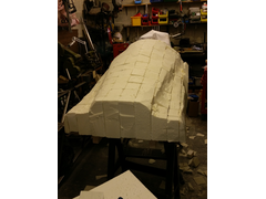

Description
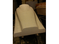

Description
all comment's taken , and read , with a smile 
getting there slowly due to cold weather and work load
bit more body filler and sanding to go
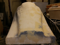

Description
Coming along nicely.
Good work - keep going 
hi all
body progress slow due to work
but!
you know when your tired and you have taken to surfing the net
well found on grabcad , a 3d model of a Chevy ls3 engine which apart from the sump is the same approximate dimensions to a LS7 engine 500 bhp and
600bhp easy to obtain !
so like you do I down loaded it and put it in my chassis
well what do you know "it fits"
just food for thought !
now where did I put that transaxle ? LOL
ps not an April fools joke it does fit !
Description
Go on do it !!!!
I think there is an offshoot of Deronda that use an LS1 in their US spec car with a slightly longer chassis.
IMO the LS3 is a bit of a bargain, looking at new crate prices you can get a 480hp kit for around half the price of an LS7. For transaxles look at the
usual porker g50 upside down or the Audi 01E both used in Ultimas/GT40's.
hi all been a while !
getting very close to finishing the back end plug
pictures look worse than it is as taken when primer coat was half wet half dry
since pics have filled a bit more and have now ordered the resin coat which will give a hard surface to work from
at the moment think I have reached the point where I am doing more damage than going forward
whilst doing the endless hours of sanding have had some interesting thoughts on an ultimate single seat road/race car will start a new thread for
comments.

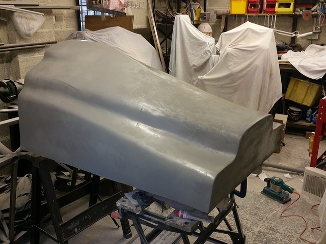
Description

Description
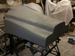

Description
[Edited on 7/4/15 by bart]
Coming along nicely mate, such a big job but will be worth it to have something one off!
disaster but retrievable i think
I have now rubbed down , filled , rubbed down , filled and so on and so on umpteen times including 2 thick coats of easy composite polyester resin
primmer and a coat of gloss as well.
now the problem.
I used pu insulation board to make the buck , fine does not interact with resin no problem .
BUT !
it does move like a fiddlers elbow with temperature and the pressure of sanding. ( to lower density !)
so I rub down ( tried hard pressure , low pressure ) and the body looks perfect could not be happier
leave for an hour or so and its crap ( only talking 0.2 to 1mm here ) I can see and feel the sunken form skeleton.
enough to make a bad mould.
solution ( for that read copious moaning and tea drinking and thinking )
I had the idea that I need to stabilize and give strength to the surface .
so I hatched a plan cover the outside with a thin layer o woven cloth and resin
spoke to easy composite's . ( very very helpful and friendly, highly recommended ) . and they agreed
so that's the plan , never mind the last four weeks DOWN THE PAN.
so waiting for the delivery , and then its forwards I HOPE !
so a warning to all
1) if making a skeleton type buck with pu foam infill , use cheap insulation for the underlying bulk then the proper high density for the outside
1>2" id say
2) if its a large buck you will need more than the 2 coats of primer stated on the easy composite video , having spoke to them 5 or 6 thick coats or
more for large surface areas !
3) don't flog a dead horse , hopping it will get better , step back analyse problem , " then flog the dead horse " lol ! , no ! change
tactics .
4) hopefully there's a solution to every problem apart from inevitable death
if any one thinks I should list this warning separately for all those that don't look at this posting let me know and I will do , but i'll
leave out the inevitable death part !

[Edited on 15/4/15 by bart]
I made my pattern with foam and plywood, then applied some filler, then a layer of chopped strand matt and resin, then a lot of body filler and
finally some surfacing filler, and I still had some evidence of rib print through in some areas. If I did it again (ha ha ha ha!) I would put 2 layers
of CSM on.
Cheers
Fred W B
[Edited on 15/4/15 by Fred W B]
just ready for gel coat
fibre glass tomorrow
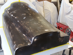

Description
defeat , a plan ,triumph , relief , joy
well hello all .
1st Despair and defeat
no matter what I tried , I could not get the buck to behave , I could get it perfect then 1 hour later skeleton marks would appear again , this is in
spite of several thick coats of resin , I was going to fibre glass the buck then fill again and reshape but that would have made it to big so that was
not an option. ( to be truthful I was also completely p****d off with it )
2nd A plan emerges
so I decided that all of the defects where negative on the buck so they would be positive on the mould . so I thinks **** this
ill make the mould and rework the mould as all the defects will be proud and easy to address.
3rd triumph , relief and joy
so extra thick coat of gel coat * 2 to allow for rework 2 thick coupling coats , and 4 coats of uni mould ( brilliant stuff if very hard work ) , had
a problem after coupling coat I got Nora virus that night and could not work the next day and you only get 48 hours to get the outer coats on , did it
the following day still ill and not eaten and drank any thing for 36 hrs , nearly passed out several times . " message to self I am a brave
little soldier " " my mummy said so" 
wait 24 nervous hours to cure
up end the mould , 4 large plastic wedges and a big rubber mallet .
tap tap , tap tap , wack wack , WACK WACK , out it pops ,perfect ! oh the relief of a released mould !
now need to let it season for 48 hours then wet and dry any scratches ( positive on the mould ! ) and re polish the mould , job done I hope
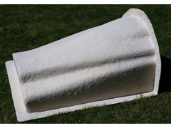

Description
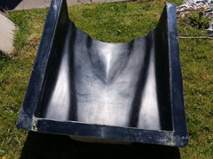

Description

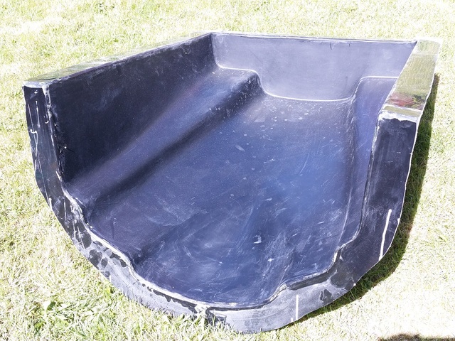
Description
the surface looks a lot worse than it actually is on the pics due to release wax , dust from the garage ect , wont take much to flat .

Description
finally the worlds most expensive dog kennel ! and I don't even have a dog .
[Edited on 27/4/15 by bart]
Always a scary moment! Glad it's good - are you planning to infuse the part?
Great progress.
Its threads like this that make me avoid bodywork and GRP
hi had 24 hrs to relax
so thanks for the reply posts.
yes looks like wet lay infusion over carbon cloth .
this is for 2 reasons
heat - parts going over engine and exhaust
and lightness
what I might do is make a cheap fibre glass part first just to check fit over frame
I also need to make this part before I can continue with other parts .
then i'm thinking do all the infusion and high temp cook off in one go. well over a month.
adding some supports to the back later today so I can turn the mould on its back and work on it.
also will add extra strength although the mould is very strong
so its hunt the vacuum pump some time this week
Not sure how you could do wet lay infusion! - it's either wet lay, or infusion (vartm)
I've found pulling a cheap part with CSM GRP is worth it, helps the mould's surface reactivity - grouping all your infusions helps you get
in the 'groove' seems wise, smaller parts you can parallel run.
easy composites pump is good (if pricey)
thought infusion was suck in the resin ie: wet lay , don't understand the technical term difference
is wet lay just paint on and per ordinary fibre glassing
any how i'm going to suck it in ! using high temp epoxy resin from easy composites
Yes wet lay is painted on resin- though you can wet lay and then vacuum bag to consolidate. infusion is a "dry" process
[Edited on 28/4/15 by cloudy]
the one I intend to do is as per the easy composites bonnet video
dry cloth
packing bulking layer
dry cloth
suck in the wet resin - so what ever that's called i'm'a going to do that .
ps : this is all new to me , leaning as I go along , before id started I had never even fibre glassed a hole in a car wing before .
well just finished making the first rear panel
so thought id rush in and post a pic
last couple of days flatted the mould.
was warned that first out of the mould can be tricky so
8 coats of wax
and 3 sprayed coats of blue pva ( that's what's in the pick by the way the parts white )
this is only a test part for fitting as the correct part will be carbon fibre
made the part from 1 heavy coat of white gel coat
2 coats of 450 grm matt
then leaving it only 3 hours ( to stop sticking )
out it popped
I shall be naming the baby - rear engine cover the 1st 

Description
Wahey!  Great start
basic trim and fit to chassis for a look see
needs further trimming , BUT its filled me with enthusiasm again , well a bit more than I had!
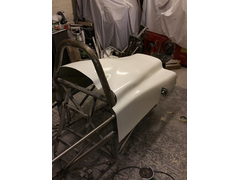

Description
now trimmed to height all round and trimmed to accept side pod LH
looking tomorrow to trim side pod and start to finish side pod ,
also thinking about rear lower panel , this should be quite simple as it should be just mdf shaped to size ( we shall see ! )

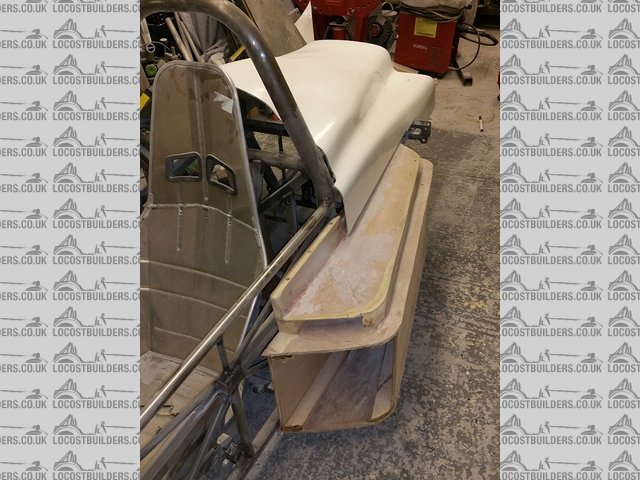
Description
also looking to extend side pod top to cover shock mount , that should avoid an iva problem
could not decide what to do with this area , the solution has only become apparent now I can see it "in the real"
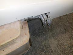

Description
looks great
well hello all
managed to get 4 hours on the car today
started to work on the side pods now I can see what's happening with the rear engine cover
its amazing what a bit of glue , some pu foam sheet and some bondo will do.
extended the rear of the side pod to cover the rear spring hanger
my only concern is i'm working free hand and I have to make the RH side pod the same . should be doable
my aim tomorrow is add some run off patches and slap a coat of fibre glass on to stiffen it all up and counteract the foam moving
" see I am learning from my mistakes" !
also did a lot of the pu sanding outside , I think the neighbours was not expecting snow !!!!
first reminder of how it was


Description
front view LH side pod basic shape archived just needs a bit o fettling
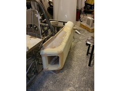

Description
rear view showing over spring add on
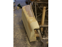

Description
oh and just to say this mould needs to be a split mould to avoid locking
I recon it would come out but i'm not going to take the chance.
had a good day today further progress
finished roughing the mouth area of the LH side
and the brought the RH side up to the same spec and they are quite symmetrical , to my eyes anyway
trotting on nicely now but wont be working on it tomorrow mothers 80th birthday party !
still back on it Sunday , interrupted by the f1 grand prix.
will look to rough sand them , get them fully symmetrical and ready for over coat of fibreglass to stiffen it all up
going to make the rear panel as well so three moulds at once ! " getting cocky now" something's bound to go wrong !
had a good look at the shape and recon the moulding will come out without a split which make things much easier .
here's todays end pics

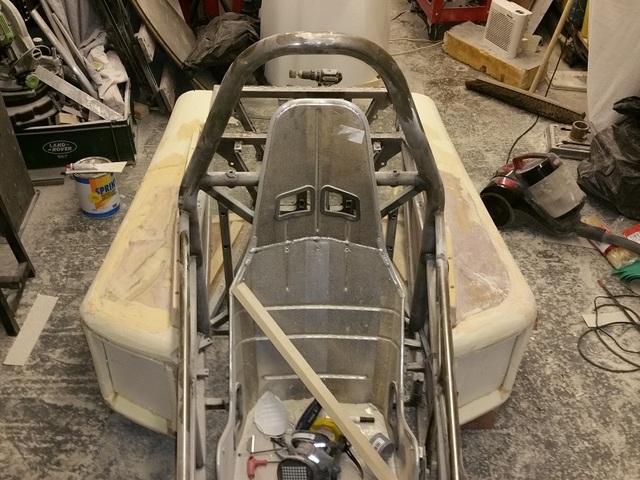
Description
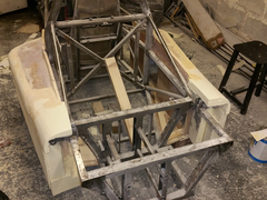

Description
well I watched the f1 , boring !
and then went out and got down to it
first both sides are more or less identical now.
so did final frame fit then extended the run off areas for the fibre glass
ps: that's why they now look out of proportion in the pics
will put strengthen flanges on very last job as easier to sand down and work on without them
gave them both a really thick coat of gel coat " makes the look awful
but it will be a good base to sand down
then I can plasticien any roundy bits I need mainly round the air intake
and then add a strengthening layer of fibre glass to act as a base for filling and sanding.
must admit the look awful in the pics , nothing 30 minutes with a da sander wont fix oh and a tub of bondo
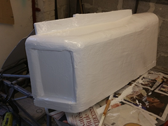

Description
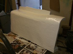

Description
hi all
i've been doing work on the side pods but its a bit fill sand fill sand so I did not bother taking any further snaps
how ever feel as if I have got somewhere now
was not happy with the shape so I did some free hand remodelling!
much happier with the result now
not finished shaping and filling yet but getting close
gave the pods a coat of white paint tonight to show up any differences and problems
will let that harden over night and do some more minor filling and sanding tomorrow
my aim is to get ready for mould making by Sunday.
tip !
I'm sure this has been done by others but this tip works really well.
I mixed ordinary fibre glass polyester resin with fillite powder , it makes a spreadable filler that goes hard ( when activated ) in a couple of hours
and is far cheaper and easier to work with that body filler . I mixed a very high 50/50 mix by weight and it worked a treat.
is also very easy to sand. needs a hard layer of resin to finished when moulded but you need to do that as a final thing any way.
its a bit like plastic concrete. WELL GOOD !.
also found a neat way to make a flat side
I got the to and bottom correct then put some gel coat on the side and dragged a straight piece of steel bar across the surface.
bit like floating concrete !
result no hollow patches worked a treat again
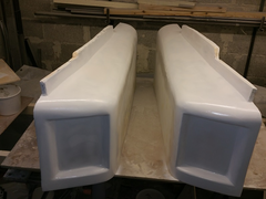

Description
rh and lh together
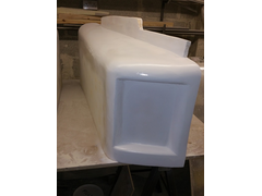

Description
lh

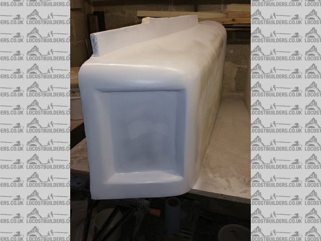
Description
rh
[Edited on 19/5/15 by bart]
hi all
some pics for those following.
this is last base coat primer resin for moulds
first coat was put on and flatted
this coat will be flatted tomorrow
then a hard coat go's on this gets flatted down to 1200 or 1500 grit then polished
pictures don't look flat as the resin was still wet and at this stage is very shinny ( well that's my excuse !)
still on target I think to finish moulds by end of Monday.
they can then season for a week then ill pull a pair of moulded parts out for a look see.
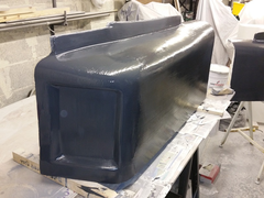

Description
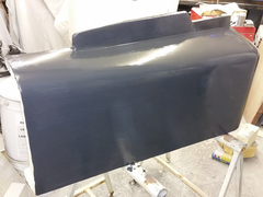

Description
ps : getting a little reaction from gloss show paint I used will have to watch how that goes.
pps : brought an electric da sander from machine mart . what a tool highly highly recommended cuts work load by 90% at least
looks great, do you get your abrasives for the DA from machine mart as well?
Some
Also from commercial body paint suppliers and ebay
All seam to be good
Get from 40 to 800 grit
Machine mart on pads is very expensive
Sander part no 6462010
hello all
did not quite get as far as I wanted had to spend some squirrel time with the wife ( ooh look at that squirrel ect ect )
as well as falling asleep on the couch a lot ( old age )
got the lh pod full finished and ready to mould in fact as I wright this I am waiting for the mould release to dry ( 5 more coats to go , going to get
the gel coat on tonight even if its mid night !
rh needs final sanding then that's ready to go , so new target is fully finished by next weekend.
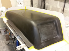

Description
finished waiting for mould release agent and a polish
well its 22:50 and the first gel coat just went on
going to get second coat on tonight as well
got the heater on full in the garage recon 1:30 am for second coat if it's gone of enough
should then be able to finish that mould by tomorrow night and pull it on Wednesday.
I can then use the same flange plastics to make the rh pod , will get that sanded tomorrow in-between fibre glassing.
You are making some great progress.
1.20 am and just finished final gel coat
Will try to get up early to put a coupling bonding layer of 100 fibre glass first thing before work.
Then I can put bulk coats on tomorrow night.
[Edited on 26/5/15 by bart]
hi all
well I managed to get the coupling coat on this morning before work so all going to plan !
next stage is the bulk mould coat , the one that provides all the strength , aiming to do that tonight and de mould in the morning

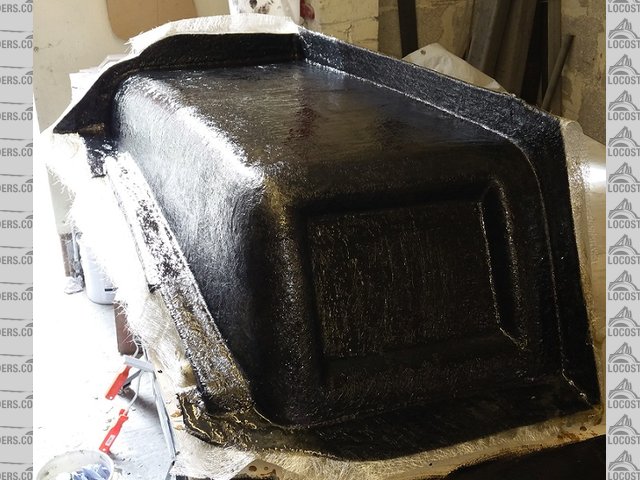
Description
hi all
managed to find an hour dinner time to put the unimould resin on ( 4 layers )
and have just de mounted it from the buck
I am pleased with the finish
picture looks rougher than it is due to dust and wax all over the mould
rear looks terrible as its covered in white dust from the rough trim up I performed
on to the rh now.
sanded it tonight and went to far in places , think ill stop for the night as i'm tired rushing and making mistakes .

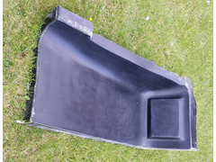

Description
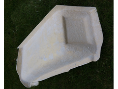

Description
Coming along now mate, won't be long till it looks like a real car! 
hi all
nothing to exciting tonight just the RH side pod mould is done
had a bit of excitement with TNT delivery's , they lost my unimould overcoat resin and I had already laid down the coupling coat Wednesday night
, wife waited in all day Thursday , no delivery , and covering time running out ( 48 hrs apparently )
so got up super early this morning 6 am ( WELL its early for me ! )
and dashed down to stoke for easy composite's ( highly recommended company , technical advice excellent ! )
picked up some more resin and dashed back.
made the mould and left to self cook ! ( this resin has a thermal reaction to go off )
popped the mould out about 5.30 tonight had a quick trim and looked the door will finish tomorrow
wife gave me a funny look when I innocently announced that " I just going out to the garage to pop my mould"
personally I cant see anything funny with that statement 
still on the buck and not trimmed
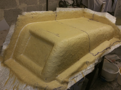

Description
and now with a rough trim up drum roll the RH pod mould . dust an all

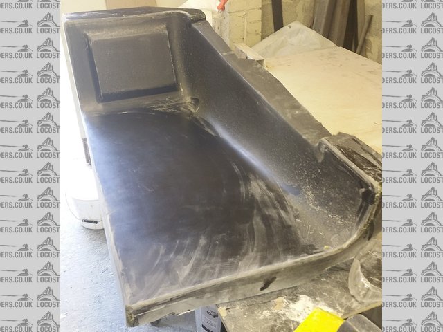
Description
ps: my original resin order turned up at 4.30 today !!!!!!! , would have just been in time but could not take the chance
pp***sss : also had some real fun with my face mask "TAKE NOTE" . brought a face mask with cartridges from a well known
supplier . I asked for dust protection and organic fumes.
well when using it for resin and paint I can still smell the stuff although not as bad as without the mask , the other night after feeling a bit tom
and dick after a resin session a sat down and read the code on the side off the supplied filters , cross referenced them on the interweb and it states
" dust only" no wonder I've been feeling ill after use.
went out yesterday and bought a proper dust and fumes mask - the difference is - did the moulding today with the new mask and what do you know no
smell no feeling ill !
motto of the story don't believe anyone check yourself !!!!!!!!
[Edited on 29/5/15 by bart]
It's been interesting following your mould making progress. I ordered a resin infusion kit from easy composites this week with the intention of taking moulds off some of my existing parts and making a few new ones before making some c.f. stuff. Looking forward to getting started now!
3M 4255 is a good organic and particle disposable mask - pretty cheap
yep that's what I now have a 3m 4255
the original mask is good just had the wrong cartridges will still use it for dust and keep the 3m for resin and paint
hi all
bit boring but I know some are following the process
so this afternoon and evening I trimmed the LH and RH side pod moulds
gave then a good scrub with 1200 wet and dry to get rid of any raised scratch marks
then gave each mould 6 coats of easy composite chemical mould release ( I should be on commission here ! )
then just for safety 1 coat of wax for insurance
gave them a coat of gel coat nice and thick as they are only temporary parts ( famous last words) for sizing
I have cut the fibre glass up ready for tomorrow morning I should be able to do both sides in an hour and a quarter.
then i'm then going to look at the front and side design again , when the parts have gone sticky ( about 3 hours ) ill probably stick them out
side so I can get the chassis out again ready for releasing the parts later tomorrow night.
cant wait to see the back and side pods together .
well here's hoping the parts come out of the mould !!!!
first pics rh side all cleaned up ready for gel coat
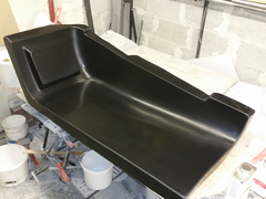

Description
second pic is the lh side with gel coat on

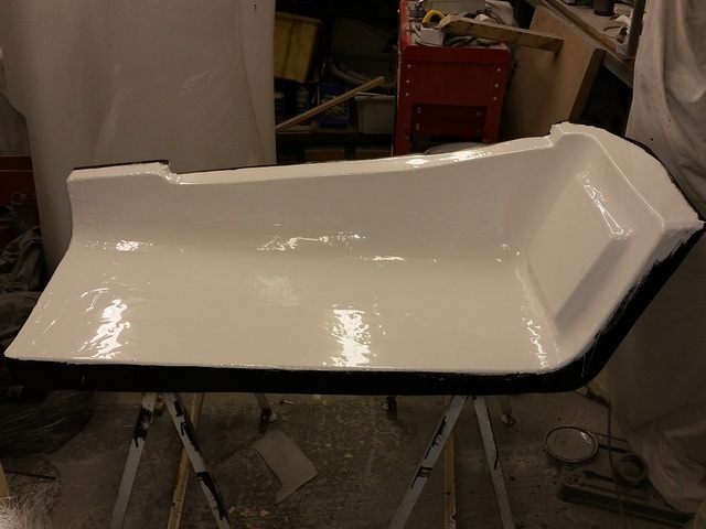
Description
[Edited on 30/5/15 by bart]
Looking forward to seeing them on the chassis.
hi all well I had a good day
got up late about 10.30 ( my excuse was it was cold wet and windy and the bed and wife was warm )
dashed out and laid the fibreglass (3 layers) in the first mould left that to go of for an hour
went and made some fantastic fried bread rolls
after brunch and tea went back out and laid the fibre glass in the second mould
retire to couch more tea and Sunday afternoon film.
went back out about 5.30 and popped both parts out of the moulds " well pleased with the result.
put them outside in the sun to harden a bit more.
big clean up of garage
about 7 pm trimmed the 2 mouldings with a dremel then a small grinder.
at this point I was going to leave it for the day , but could not wait to see them on the chassis with the rear engine cover
so further clean up and get the chassis out from the side of the garage.
over the next hour I trimmed the rear engine cover for a rough fit up , not fully fitted and dressed yet but well on the way
as I said a good day
just out of the mould and untrimmed

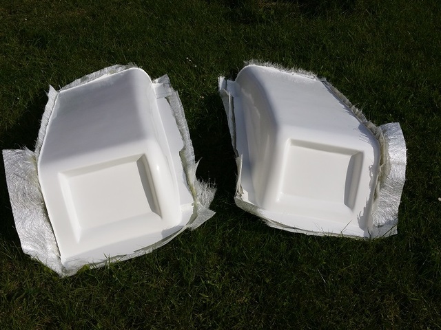
Description

Description
side pods after a quick trim up , " short back and sides "

Description
this pic is the pods in position but the rear cover is not trimmed and is 2" to high

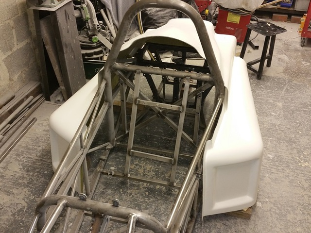
Description
this is front and rear view with the top now trimmed

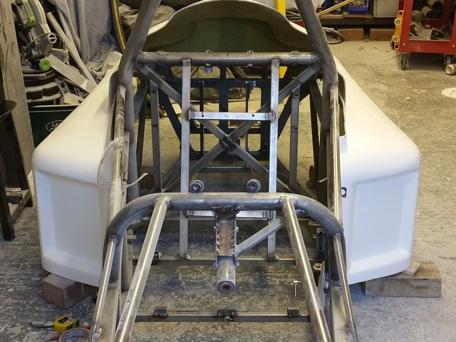
Description

Description
finally bit out of sequence but side pod and rear engine cover roughly trimmed
the pods still need trimming to height about an 1" to come off the bottom of both
going to do that much later when fitted and mark it out with a height gauge from the floor

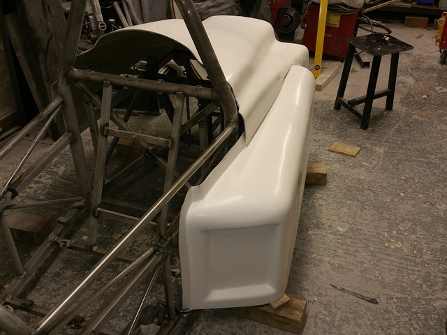
Description
You have cracked on, looking good now! Cant wait to see it all together!
Looking good.
hi all
well tonight I decided to get on and design and make the rear lower panel that goes at the back under
the engine cover , ive include a design pic because I forgot to take a pic of the foam buck I made tonight
ive got to the stage of just covered it with a layer of fibreglass to give it some strength
tomorrow night I will final fill and sand with a view to getting it ready to make the mould on Thursday
also working on the side panel moulds ( well i'm giving it a lot of thought ! ) 
trying to get as much as possible done this week as I start a new job next week and it6s long hours through the summer
so I expect things will slow down considerably , not ideal but I have to buy food ect and I also need some more car vouchers for bits . picture shows
pockets for the fog and reverse light but these will be surface mounted
number plate goes in-between the lights , long thin front style.
could not get the rear type plate to look good.


Description
hi all well i've steamed ahead and have finished the rear lower panel for the mould make.
I will try and get this mould done tonight ,should at least get the gel coat and coupling coat done today
I have also started the side panel mould , I have redesigned it so as one mould makes both sides lh and rh
I will have to alter the frame slightly but it makes for a better frame and one less mould I will post some more pics on this today or tomorrow.
original cad design


Description
what ive finished up with as stated before the lights will be surface mounted so no need for sunken holes
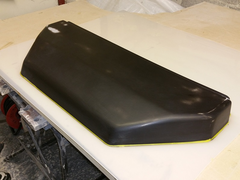

Description
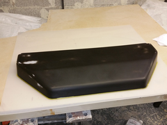

Description

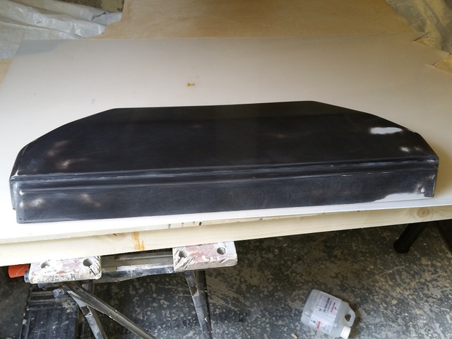
Description
that is some rate of progress, this feed puts me in mind of the BBC shows with all the fab time lapse photography except in your case it is all in
real time,.....
well impressed!

hi all
i'm on the scrounge
need to borrow a front nose cone to off up to my car for size
it wont get marked or scratched and I will pick up and deliver back safely
no particular make required
so can anyone in the north west help me out preferably in the Liverpool Manchester corridor please but any where north west will do
ps : it can be old and cracked it don't matter .
regards Gary ( Bart )
hi all
got out at 9.0am this morning and put the backing coats on the rear lower panel mould
got five layers of fibreglass on in one go as it was cold and I wanted the extra layer to help with going off
got a bit worried as it took 3 hours to even go tacky , but all was ok in the end
took it off the buck after 4 hours
gel coated

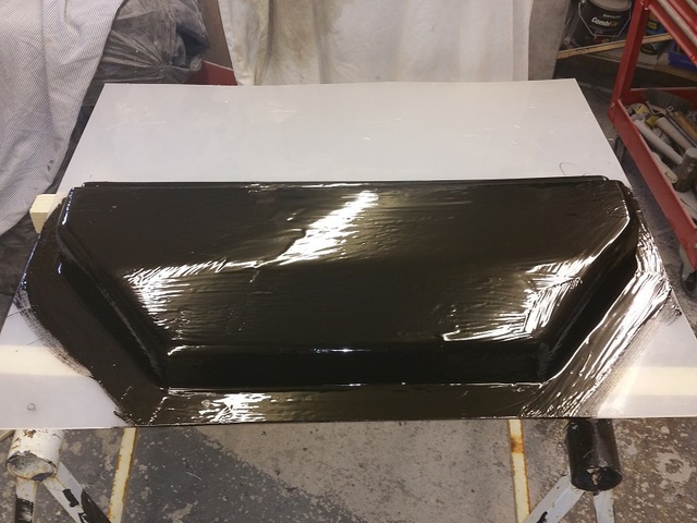
Description
rear of finished mould trimmed round the edge
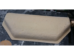

Description
2 inner mould pics still dusty and with some wax on as just of the buck

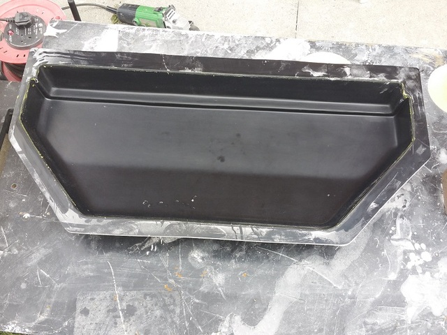
Description

Description
I will leave this for 24 hours to harden off fully and get rid of some of the styrene.
second post of the day so hi again !.
these next few posts will be regarding the side panel
first I had a look at the design of the side panel and by altering the design of the chassis slightly
I came up with a design that6 could be used on both sides so one mould only required.
basically I use the left hand side of the mould for one side and the rh side for the other side of the car
the middle section is common.
this is the design I came up with
Description
so I have constructed the buck mainly from plywood this time with no foam as the other moulds.
I used this construction so as to make flat surfaces relatively easy.
I used 4mm ply as the final skin so that the panel steps were easy to get , hopefully the pics show this
basic panel construction

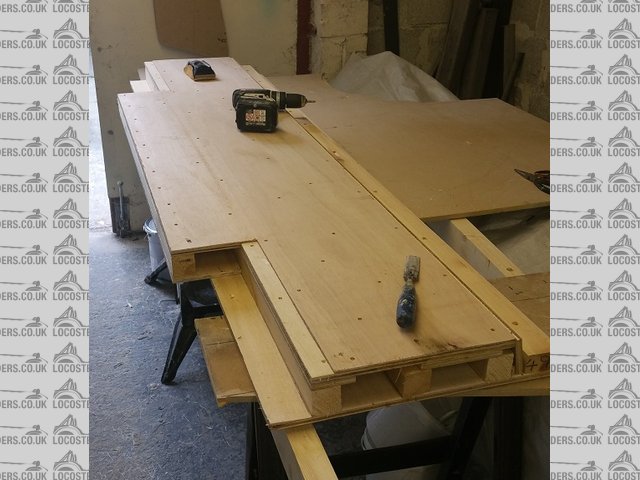
Description
closer pic showing the panel step that I require
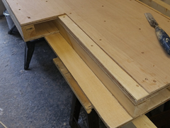

Description
last pic of the day , as I'm kna----d ( very tired ! )
this pic shows capped of ends some basic filling and top edge rounded off
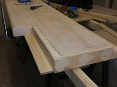

Description
tomorrow need to form the bottom step and round of the back of the panel
then ill give it a coat of fibre glass resin to seal the surface , then a coat of gel coat so I can see any problems and differences
hi all
bit of a slow down now as I only get 1hr per night on the car
I have sanded the wooden buck to size and form and in the pics below they have the first 2 sealing coats on.
when dry tomorrow I shall sand down with 120 grit to get a good finish and the progressively down to 1200 grit
will probably need another coat or 2 but we shall see after the first flat sanding.

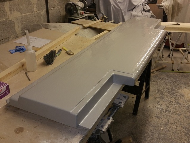
Description

Description
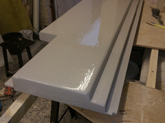

Description
if I can keep awake I will design the front side panel tonight that goes over the front suspension mount points and locates the front nose.
hopefully the plan is to get all the body work moulds finished by the end of July . then its on to learn carbon fibre infusion technique's
hi all
I have finished the side wall buck and have included 2 pics for interest
this mould requires 1 split line so the pics show the first split line
from the pics you can see the plastic surround and location pips straight out of the easy composites video
ceebmoj came round for a chat today about his body work plans so all the best to for his work.
hope all goes well

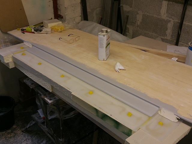
Description
and a close up of a location pip as per easy composite video

Description
as I post this its 8:20 pm and the second release coat has just go on . looking to get gel coat * 2 and a coupling coat on tonight if possible lets
see. if I can then I can get the mould back done 7:30 am and let it go off while I go out for a squirrel day
I can the flip the buck tomorrow night and start on the face side
[Edited on 13/6/15 by bart]
hi all
well managed to get the gel coat and the coupling coat on the reverse split side last night
got up at 8am and completed the backing 5 coats this morning
about 1pm I decided it had all gone off enough so I turned the buck over and removed the split line plastics and backup
leaving the mould in place
you will notice that I went well outside the prepped area on the rear face this was so that the rear split mould would remain firmly
attached to the buck and when the front is finished I will simply put a grind line in the correct place to remove it.
I am now working on the front face and waiting for release chemical's to dry so thought id post in-between.
first pic shows all the location pips and surface before moulding.

Description
next shows rear moulded area with "sticky to buck area in black"

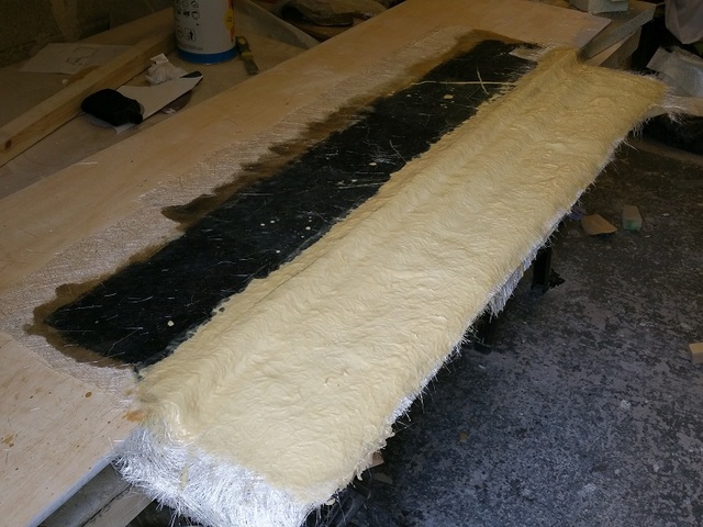
Description
this pick shows buck turned over and plastics and wax sort of removed ready for clean up

Description

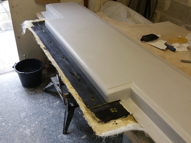
Description
close up of location hole and slit line prior to trim up with cutter grinder

Description
all cleaned up ready for top moulding
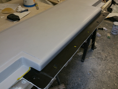

Description

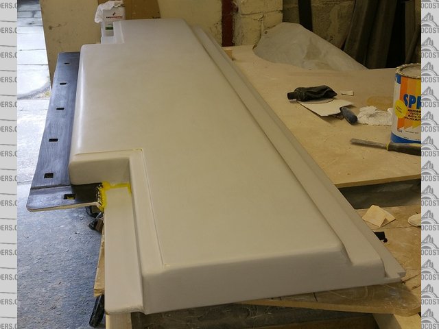
Description
[Edited on 14/6/15 by bart]
slap on a bit o gel coat liberally


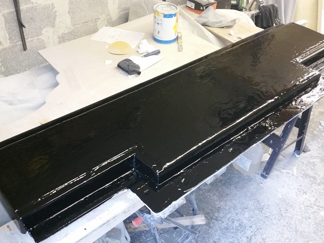
Description
well hi all not much to post tonight
rushed home from work and got ready to layup the backing coat for the side panel buck tomorrow
then thought oh what the h--l I'll do it tonight
so had to cups of strong booster tea and got down to it
this was by far the most hard work mould I have had to do .
but there again it is 3 square meters in total
got four layer in most places and five in some where possible
if any one wants to know in materials alone this mould has coast £250 easily probably nearer £350
and lots of hard work
just hoping it all comes out ok tomorrow night and the split line works !
now I need to save some car vouchers for some more uni mould resin £147 + vat + carriage for 25 kg and I used 20 kg 0n this mould alone that's
without gel coat and coupling coat . not moaning just for information for the people interested.
if it comes apart ill post tomorrow , if not you will hear a loud sobbing sound coming from Manchester way !

Description
ello ello
well it came out off the buck easy and the split part looks good and fits good as well
pics are with a basic clean up from last night. only spent 45 mins on it tonight bit tired so bath and bed tonight.
at least I know its off the mould
big clean up tomorrow , dust resin and fibre class every where.
then probably a big contemplation tea to decide what to do next.
ps: the easy composite location pips work a treat.
have to say they are not the cheapest but there stuff works every time.
highly recommend there easy release , if you consider the surface area of this mould it just almost fell off.
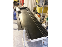

Description
pic showing location pips
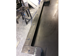

Description
pic showing split line rear of mould
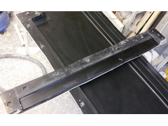

Description
reap slit half back in place
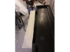

Description
Looks great, As I mentioned at the weekend you are flying along. I wish that I had made as much progress as you.
hi all
still having some squirrel days but did go outside to my ever increasing pile of discarded old bucks and cut the end
of the side panel buck as I intend to re-use this part and modify it to make the front side panel that covers the suspension anchor points and
provides an anchor for the front nose cone .
thought this pic may be of interest to some as it clearly shows how I constructed the layers and structure for the side panel buck
sort of a real life cross section

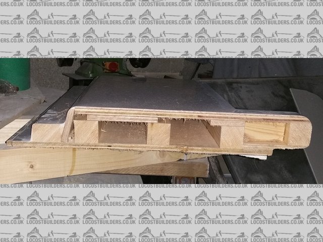
Description
What do you use as a sealing coat on the buck? I'm going to start making up a side panel buck and mould soon.
In this case because the volume of the shape is wood and solid I coated the shape with 2 thick coats of white gel coat . I flatted this down then applied 2 coats of a mixture of 50% gel 50% polyester resin . And some black pigment. Much cheaper than using easy compasite mould coat and just as good. P's I think my poly resin has wax in it to make the air side go hard. If yours don't use 2% wax added . Then I sanded down to 2000 grit
hi all
spotted a problem that I should point out
ref: side panel mould
this mould as stated was all wood construction and had no covering of fibreglass just 4 thick coats of resin
looks like when I came to tidy up the mould and close inspection that I got a leach through where the layers of plywood are.
these lines where defo not present before I covered the buck so must have been draw through by the mould gel coat . not a disaster but worth pointing
out. most have rubbed out the rest can be dressed in the part due to painting , think I would advice to put a layer of 450 gm chopped strand on the
mould buck before rubbing and filling to act as a further barrier.

Description
hi all
well had a few days off , I was exhausted what with a new job and working in the evenings on the side panel buck.
more on the side panel in the next post
first the rear panel
spent several hours this week end making temporary fit up panels from the moulds I had made over the last few weeks
first the rear panel , nothing to report ( unlike the side panel more later ) just pics of the trimmed moulded panel as usual almost fell out of the
mould.
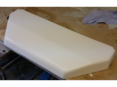

Description
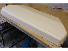

Description

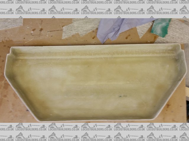
Description
ps: word of warning , if you want to get spectacular static electric shocks do the following .
hold and use a dremel cut off blade in one hand and hold your nylon vacuum cleaner nossel about 1" from the cutter whilst both running RESULT
!!!! got three before I realised what was causing it LOL DOH i'm thick you see !
hi all
well this is a late post , I actually made the first side panel from the moulds last weekend , but have not had the time to post
Its not a disaster but the return edge at the top is near impossible to mould using conventional layup methods. I managed to get a very rough moulding
for fit up trials which is what the panels are for but I will need to modify the mould for further use.
having said all that when I make the proper car panels they will be vacuum bagged which will be a lot better but I still need to modify the moulds to
make sticky down areas for vacuum seal. I also need to make some more clamp holes nearer the split line to improve that area.
any how i'm on with the front suspension infill panel which when finished will allow me to make the front nose cone and front bonnet . will take
some pics later as i'm just going to Glasgow to watch AC-DC.
finished first side moulding
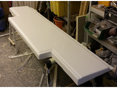

Description
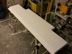

Description
the trouble some return top edge ,
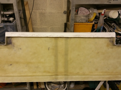

Description
hi all started work on my front suspension side panel infill
again this is both LH and RH
started with my front half of the side panel mould chopped off
added some angled bits to cover the suspension made from ply , wood , glue , sticky back plastic , you name it its in there.
covered in half a big tin of body filler strategically placed rubbed down and have just got to the first coat of cover gel
tomorrow I will rub down change any bits I don't like then 3 more coats of tooling gel ( actually its my own concoction ) . then rub it all down
stick to plastic sheet and tool up.
aiming for end of the week tool finish .
will see how it goes got about 10 hours into it so far.

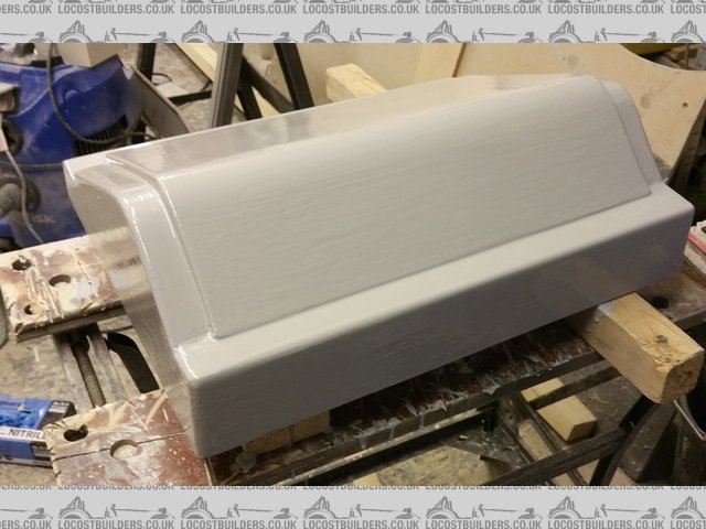
Description
top view

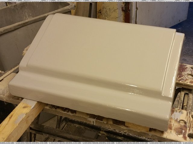
Description
bottom view

Description
side profile view
What is the tooling gel made up of? I think you said microsphears, pigment and resin. How does it build and sand compaired to the of the self products?
ah ha
after my secrete recipe's are you 
I have 2 both for building the surface of a buck
No1 50% polyester gel 50% polyester resin use 2% hardener , this gives a coat not as thick as gel easy to rub down and resilient .
I use premixed white gel for fibresuplies Southport with a kitchen knife full of black pigment to add some dark colour for contrast.
No2 50% polyester resin 50% fillite balls use 1.5% hardener ( total volume ), this gives a thick cement type coat easy to rub down . good for
"free hand design" with a kitchen knife full of black pigment to add some dark colour for contrast. on a flat surface this can go on
1/2" thick or more 2 -3 mm on vertical
"to all this add salt and pepper to taste and a dash of tabasco source" 
hi all , nice weather , hot , f hot , cold , warm , hot
just a pic of the front suspension infill panel , gel coated ready for 100g fibre layer as intermediate .
will do full mould first thing tomorrow then leave to dry whilst having a squirrel day .
ps: come on LH

Description
Hi, i was reading through the Uni mould documentation and cant find details of how much you let the coupeling coat go off. What are you doing?
7 or 8 hrs minimum
Max 48hrs
Apparently acording to easy tech bloke you can leave it longer but you have to sand prep it and wipe with acetone if longer than 48 hrs
well a word of extreme caution today
easy composite's was out of uni mould
so I went to east coast fibreglass for there opti mould system
from reading its probably the same stuff !*!*! ( looks and smells the same )
easy mix ratio is .75% to 1.5%
east coast is 2% ??????
well well well
small or may be large disaster
first so far with the easy uni mould system, I have now done 6 or 7 moulds
easy to work with allows you to get the 4 or 5 layers on without a problem then goes off ok
east coast disaster
1/3 of the way through the 5th layer the resin went off in a 10second period I now have a 1/3 saturated 5th layer sticking
up all over the place half stuck down half not
fin disaster no warning just bang your "f-----d"
and no to your reply's
I did mix it very accurately
it was the correct temperature for buck and resin and no I wasn't taking my time I can get 5 layers down in 20mins
all I can hope is , that the mould is ok and I can stick the loose stuff down with ordinary poly resin
happy day's aahhhhhhh !
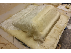

Description
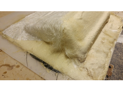

Description
what a mess !
stick to easy composite's uni mould it works
hi all
been a trouble at tut mill !
first as per previous post the tooling resin did a nose dive
well mostly got round that , covered all the loose material in ordinary resin
added a support rib so that I could turn the finished mould up side down to work with
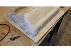

Description
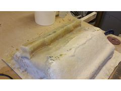

Description
well then the trouble at mill part deux !
I did a silly thing I went shopping came back had some dinner then fell asleep on the couch
result the tooling went rock hard.
now normally that don't matter but this was a particularly solid buck and the mould is also solid. ie no flex
result I could not get any wedges in to get the buck out . I tried every thing !
so cup o thinking tea and out with a 1" sharp chisel
I had to chip the inside off the buck away bit by fing bit
2 and 1/2 hours later and lots of sweaty work I finally managed to get it out
it was not chemically looked it was not mechanically looked.
it was I could not get at the seams to wedge it out.
that's why I normally get the buck out whilst its still a little green with some flex
still its been one of them days !

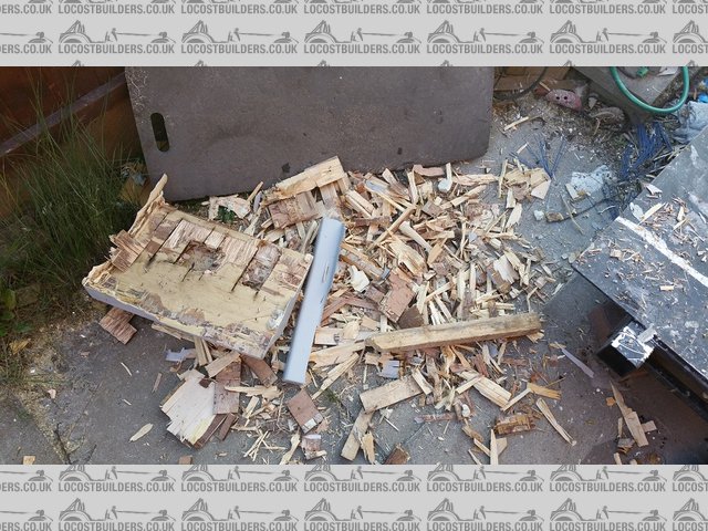
Description
all chipped out !
finished mould to be cleaned up

Description
[Edited on 4/7/15 by bart]
hi all
well it all sort of worked out in the end
all cleaned up and got some moulding out
pic shows one out and one in the bed "cooking"

Description
now on to the front nose cone probably the most difficult to do.
first I have to alter the chassis so will keep you updated as to progress
need to do some welding, so I have to hoover the whole garage first to stop it going up in flames.
if we can get some nice weather might lift the frame outside and do the mods. "the safer option"
hi been a slow week on the car
no work at all during the week to busy at work
yesterday went to Cummings factory for there 50Th open day
had a big clear up today and a big garden day ( more of a hack )
anyway got the chassis out tonight and temp fitted the front suspension cover
need to fit the other side then work out what I am going to do for front nose cone
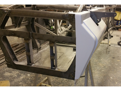

Description
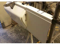

Description
Looking good mate, have you decided on a colour yet?
can't tell who's going to be finished first at this rate, when are you hoping for?
Looks great.
hi all
hi rosco next year mate lack of time and lack of car vouchers !
well got the chassis out side yesterday as I need to do some mods , and did not fancy setting light to the garage with all the body dust .
1) alter some front frame bracing in the way of panels
2) cockpit area top bars alter to square and make parallel to floor and move !
cleaned my fab table up and clamped it down
chop chop , grind grind , sware sware , tea tea , think think , chop chop ect ect you know usual thing 
temp fitted the side panel to car to get cockpit top frame correct.
will weld into place today if the wind stops .
left the frame out side over night and my canvas leaked ! much swearing ensued this morning
some pics from yesterday
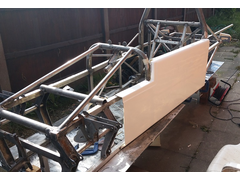

Description
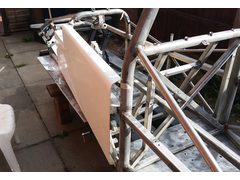

Description
hi all
not done much this week but did alter the chassis last weekend
changed the top cockpit tubes to square and made the parallel to the floor
so that I can attach the side panels to them and lean on them when exiting the car
also cut out the support tubes at the front and replaced them with some cross bracing
designed the bonnet today and have included a pic from the cad.
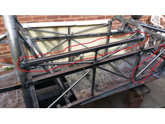

Description
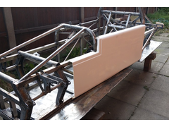

Description
Description
What's the plan for the nose? Some thing along the lines of a 7 or 60s f1 ish?
hi not sure on nose
going to make the "bonnet" and mount with the side panels then do several side view profiles to see what best suits
I can print them out on my plotter and cut them out of card or plastic sheet to see what looks good
will post pics for opinion's when I do it . probably end-ish of Aug. hopefully before
hi all
started the front bonnet buck yesterday
making the basic structure out of mdf then fill with foam and shape
pictures show wooden under buck
them foamed in and first skim of body filler
ps: I am also making the dash board at the same time so that they match exactly
also means you can mould the two at the same time
I just cut a slice out when finished
Description
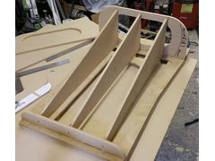

Description
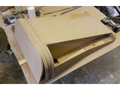

Description
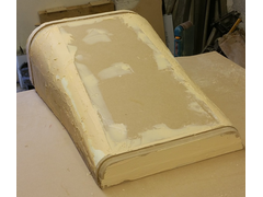

Description
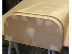

Description
hi all long time no post
been busy ect
been getting on with the front bonnet buck
here's some pictures
just needs a few more hard coats then polish down for mould
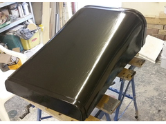

Description
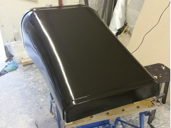

Description
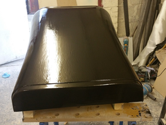

Description
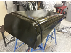

Description
bonnet and dash board mould finished
front end is the bonnet
rear bit is the dash board
like the green ?????
funky !
ran out of black vinyl ester gel coat so its green from now on
just the front nose cone to do
I will knock out a bonnet and dash board to test this week hopefully
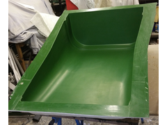

Description
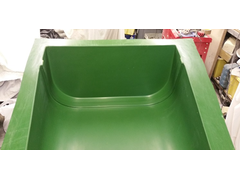

Description
[Edited on 24/8/15 by bart]
Looking good, nearly there now aren't you, I bet your about sick of fibreglassing, but will all be worth it!
Yep!
And
Yep
Wow, looks very good. I hope to do something like this one day. Keep going.
[Edited on 29/8/15 by CharlesZ]
hi all
knocked out a trial bonnet panel and dash board
had a quick fit up so that I can make the nose cone
will start that tomorrow will keep posting pics
front view
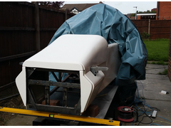

Description
rear view of dash board
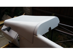

Description
Looks great!
You're making good progress. I've not done anything else on the cf front, but hope to crack on next week. In the process of ordering an
electric blanket and temperature controller...
I'm getting excited! The fit between the panels looks spot on, keep at it! Not much left now!!
Make a nose cone !
did quite a bit today and took many pics some of them posted here
first I cut out from poster board the shape that matched the front panels already made
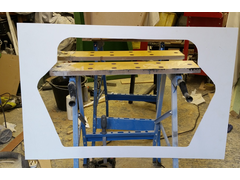

Description
then I cut out of mdf the profile shapes I needed then stuck glued them together

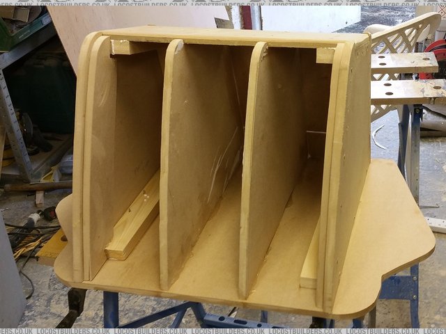
Description
once this was done I stuck panel on the outside to give it form and stiffness
the sides will be foam so I can blend it all together
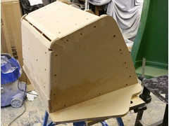

Description
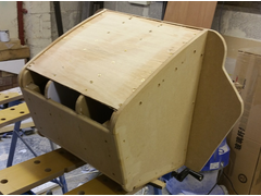

Description
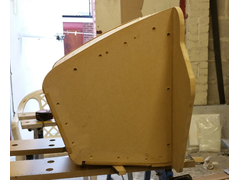

Description
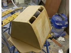

Description
hi all update
front nose cone is now 90% there
picture show final shaped coated with a layer of fibreglass
then rubbed down then hard rub down coat added ready for final rub down
the polish
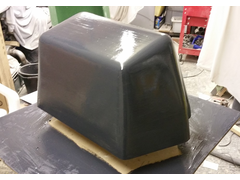

Description
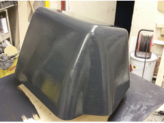

Description
hi all not posted for a while , been a tad busy at work.
any how way !
finished my nose cone mould and it came out quite nice !
first picture shows finished mould and a layer of gel coat for the first moulding.
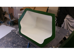

Description
fine so far ---- 
now for the not so good news
first the part fits fine just needs the appropriate trim .
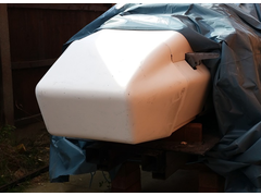

Description
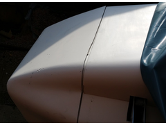

Description
now ! I made this part differently to the rest , this was done with resin infusion - my first time , a fusion virgin 
I used 1 thin coat of gel coat ( being sprayed later )
1 coat of carbon fibre
and 2 coats of 600 woven fibreglass to give thickness
and polyester resin infusion.

Description
now ! worst finish I have ever got out of a mould ( and the moulds perfect )
surface finish has print through and pulling away from the mould.
think I will try again with
2 coats of gel
3 layers of carbon fibre and some hexagon lantor soric core mat this time.
good news is the part is strong and very light
going to email easy composites with the pictures get there advice as well
any advice from you lot welcome
Hi all
been a while
been away working getting some more car vouchers
but i'm back !!! 
will have to look after the wife for a few weeks but look to get stuck in over xmas
will post any updates
Glad to hear it mate! I was getting a bit woried 
Read all the way through this and was gutted not to see a conclusion... are there any more updates Bart? 
hi all for sale
chassis rear suspension legs
all moulds and test panel set
lots of other bits , send me u2 if interested .
£400. starting point depends what you want but super cheap
yep I know lost a fortune and so much time but various reasons why not going to finish.

Sold
Bit sad but went to a good home , someone on the forum
best of luck K----
ps still got wheels and tyres for sale
and hi spec uprights
Does anyone know if this car ever got completed and put onto the road?