Mix
|
 posted on 23/4/04 at 10:25 AM posted on 23/4/04 at 10:25 AM |

|
|
FU 1 & 2
Is this a viable modification ?
I'm in the process of fitting tubes FU 1 & 2 and have made a jig to allign the wishbone brackets. I am using the book design for the bottom
bone but I will modify the top bone to suit re. castor angle. I am considering alligning the tops of the FU tubes with the J tubes, (rather than
setting them slightly inboard), when I do this the bottom of the FU tubes coincide with the outer edges of tube E.
Am I correct in thinking that this will have little effect on the integrity of the chassis ?
An additional benefit is improved access to the lower bone rear bolt.
|
|
|
|
|
mangogrooveworkshop
|
| posted on 23/4/04 at 10:54 AM |
|
|
This is the dsk mods vs catervan
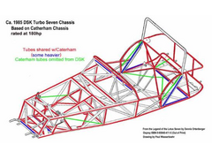 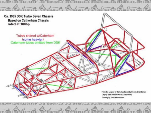
Rescued attachment dsk chassis.jpg
|
|
|
mangogrooveworkshop
|
| posted on 23/4/04 at 11:05 AM |
|
|
got a s2 pic (a lot less tubes) less horse power in those days Broken tubes common place the history books tell me. R&D was to build it race it
and fixit if it broke......brave or stupid.
Rescued attachment Lotus7S2.gif
|
|
|
Mix
|
| posted on 23/4/04 at 12:09 PM |
|
|
Here's a photo of what I mean
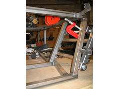 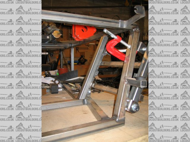
Rescued attachment FU1.jpg
|
|
|
James
|
| posted on 23/4/04 at 01:25 PM |
|
|
Mick,
I don't see any problem with what you suggest- mine is much the same (not that I've driven mine to see if it falls apart)!
And you're right about the benefit of access to the bolt!
HTH,
James
|
|
|
cymtriks
|
| posted on 27/4/04 at 11:54 AM |
|
|
My analysis of spaceframes shows that small changes to how tubes meet and small offsets such as the one shown make very small differences to chassis
strength and stiffness.
By the way I wouldn't omit the triangulation from the seat sides. This is important as it feeds the loads from the spring mounts into the sides
and also helps support the axle trailing arms and the seat belt anchorage. The curved tubes have little stiffness of their own and are there to give
the right shape, not to add strength. Take a look at my double Y braced chassis designs in the photos section. I reckon that that is as good as it
gets without departing too far from the book.
|
|
|
jcduroc
|
| posted on 27/4/04 at 01:27 PM |
|
|
quote:
Originally posted by cymtriks
... By the way I wouldn't omit the triangulation from the seat sides. This is important as it feeds the loads from the spring mounts into the
sides and also helps support the axle trailing arms and the seat belt anchorage...
Hi Chris
BTW, how come the loads from the coilovers "diverted" through the chassis as per the book? Do you agree that most of the rear section
(except for the mounting of the Panhrad rod) does nothing but hold the body?
Cheers
João
JCM
|
|
|
Peteff
|
| posted on 27/4/04 at 04:17 PM |
|
|
And you're right about the benefit of access to the bolt
There is no problem with access to the bolt, put the bolt in from the other end and put the nut on the end near the fu tube like everybody else
does . If you mount a tube across the chassis where the fu tubes sit you could mount them directly in line with the front assembly tubes. How would
that affect chassis strength? . If you mount a tube across the chassis where the fu tubes sit you could mount them directly in line with the front assembly tubes. How would
that affect chassis strength?
yours, Pete
I went into the RSPCA office the other day. It was so small you could hardly swing a cat in there.
|
|
|
James
|
| posted on 27/4/04 at 05:15 PM |
|
|
quote:
Originally posted by Peteff
There is no problem with access to the bolt, put the bolt in from the other end and put the nut on the end near the fu tube like everybody else
does.
Perhaps I worded that wrongly- what I meant was that with some setups (including Luego's race chassis) the end of the bolt goes through the side
of FU1/2. Luego's chassis has a couple of holes drilled in FU1/2 to allow the end of the thread to protrude into it.
quote:
Originally posted by Peteff
If you mount a tube across the chassis where the fu tubes sit you could mount them directly in line with the front assembly tubes. How would that
affect chassis strength?
Feeling thick- not quite sure what you mean by this.
All the best,
James
|
|
|
MikeP
|
| posted on 27/4/04 at 05:56 PM |
|
|
I set the bottom of my FU's inboard like what's shown in the photo. Not quite as far I think, just enough for the bolt threads to slip
by. If these bolts behave like other pivot bolts I've had the displeasure of dealing in the past, I'll be happy to be able to get a punch
on the end of them some day.
I've also appreciated how easy it makes it to take them in and out so many times during my build - a quick tap and out they come.
|
|
|