FuryRebuild
|
| posted on 7/6/12 at 08:31 PM |

|
|
How I made my engine mounts putting a duratec in my fury rebuild
So, as part of rebuilding my fury and shoving a duratec engine in, I decided to make some new engine mounts.
Firstly, I went to Fast Dan (DanST Engineering) and ordered some engine mount plates.
They're a great fit. I think the price is good value and there are times when buy is far better than build.
Secondly, I decided on the design, and went for something inspired by SBDev and which gave me quite a compact result and rather contradicted the
original design that was somewhat agricultural. The original design was from my previous pinto installation. When I was thinking about the best way to
do this I wanted to improve the packaging as well - the old mounts used up a lot of space that could otherwise be spent moving mass down - I have
swirl pots and fuel pumps to put somewhere after all.
Description
So, here is the assembled list of bits. Rather than go for a huge rubber mount (which of course would be good for absorbing vibrations) I've
taken a gamble on using (reusing) the bushes I've taken out of the suspension. I've fabricated everything from 32mm dia 3mm thickness CDS.
The sleeve inner diameter didn't match the bush outer diameter, so I bobbed over to a friends and put it into the lathe. It was then machined
out to take the bush with a reasonable amount of slack, knowing the sleeve will clench up a little when welded.
Description
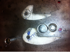
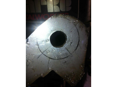
The mounting plates needed to be notched in order to accommodate the way the plates were offset when mounted on to the chassis rail. Note that each
plate is a different size to account for the angle of the rails; I wanted to feed the load into the chassis at 90 degrees, rather than an angle. An
angle would mean putting some bending load to the leg from the plate to the chassis (not ideal). In order to get the hole in the correct place for the
plate, I hand-fitted the sleeve and plates to the chassis, and clamped it with a welding clamp (you need a third hand for this, thank you Zaphod).
Then I used a CD marker pen to draw around the sleeve, added cross-hairs after dismantling and punched a hole.
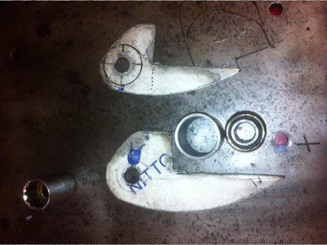
These plates are 3mm stainless (left over scrap), so you can't just go riving at them with a 1/2 inch drill bit (the bushes are the standard,
mandatory, obligatory, inexplicable 1/2" inner diameter). I started out with a 3mm hole, and went up in increments of 2.5 or 3mm, depending on
which bits I had to hand. I also found that the
cobalt set of
drill bits bought from tool-station started to show their value. A cheaper set of bits just screamed and blunted making virtually no impact on
the hole, yet the cobalt ones cut through nicely. I also used a spray cutting-oil (and lots of it) to help things along.
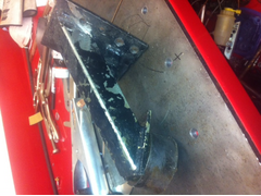
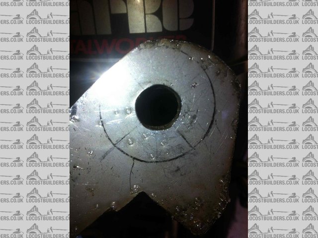
The thing you have to remember is that drill bits don't cut round holes, and the larger the bit, the more obvious this becomes. Once I've
got the hole out to 12mm, I then ream it out to 1/2 inch. I bought a tapered reamer from ebay for not a lot of money and it's done me proud. It
reams stainless out as well, but again, it wont go out more than 0.75mm. See the following as an example of how the hole isn't perfect before
reaming:
Description
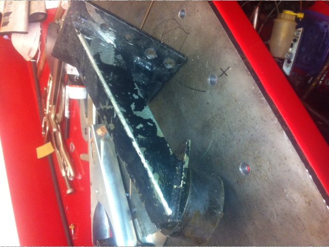
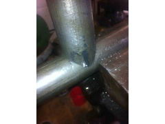
Next, I needed to machine the down-leg to fit the sleeve. The sleeve was cut from the same tube I'm making the leg from, so that was at least
reasonably simple to cut a matching fish-mouth. I used this software, printed it out, stuck it
to the tube and got busy. I cut the majority of the metal away with a 0.8mm slitting disk, and then tidied up and ground out to the the marks using a
tungsten burring tool on an air-die grinder. You can see the results yourself below:
Description
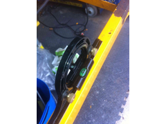
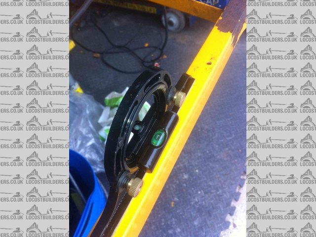
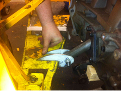
There are other things to note in setup before finally welding it together. The main one is to try and have the engine level in the chassis. I used a
spirit level on the back of the car to be sure the chassis was level (it was) and then put the same level on the flat gearbox top to be sure i had the
engine in the right place: one can't really take a measurement off the top of the duratec.
Description
I found out that chocking the engine in place was tricky - the chocks were difficult to place and kept popping out. Interestingly, a run of duck-tape
from the chassis rails to the top of the engine was a great way of keeping it in place. Duck is like the force - it has a light side and a dark side
and it holds the universe together.
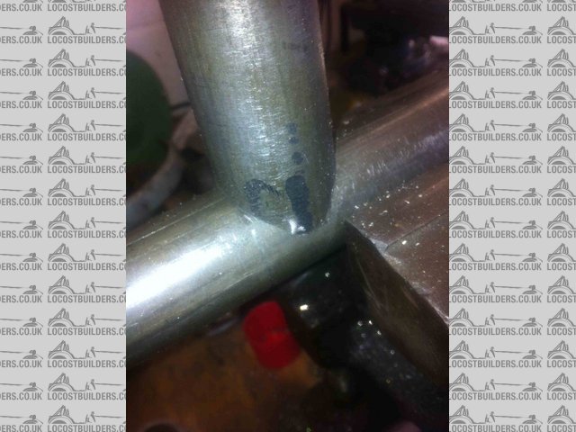
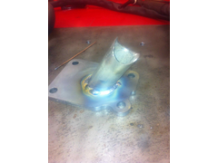
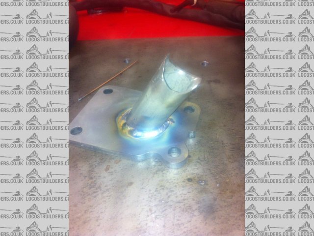
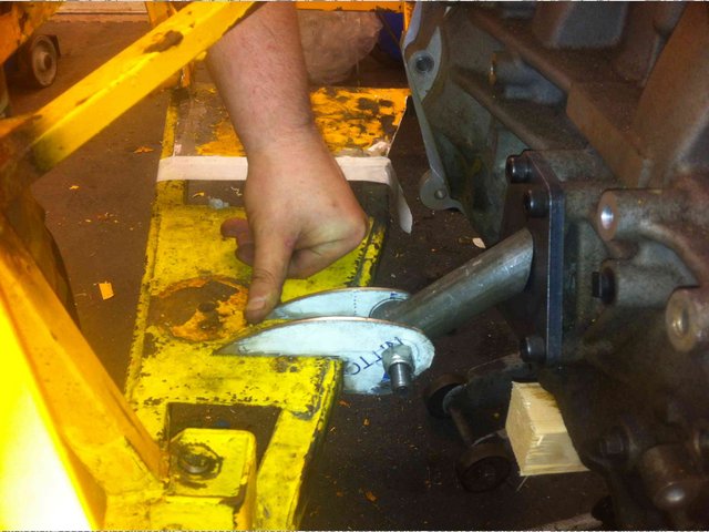
This is what the mount looks like from the engine down to the bush:
Description
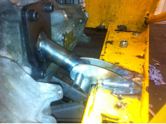
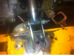
this is what the whole lot looks like when nailed together to try the fit. The offset between one bracket and the other is more noticeable on this
side.
Description
And this is what the almost completed installation looks like. There are a couple of points to note - I've put a reasonable seam in to hold the
bracket facing the camera (and the one you can't see the seam on) but I won't be able to complete the seams until I get the engine back
out. This was part of the plan - the engine is just a dry-build at the moment to be sure I have everything in the right place.
 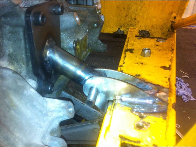
Description
I still have one job left, which is to put a bracing plate in at 90 degrees to the bracket to tie the front-to-back loads to the chassis. I
don't think the loads will be all that significant, but they may eventually fatigue the joint. I only need one plate because the bush will
transfer the load from the other bracket to the bracket with the cross-brace. It's only going to be a few grams of steel but it's worth
getting right. Even if I'm being paranoid I'm only wasting a few grams.
When all you have is a hammer, everything around you is a nail.
www.furyrebuild.co.uk
|
|
|
|
|
mark chandler
|
| posted on 7/6/12 at 09:29 PM |
|
|
That's the same setup we used on racing landrovers where you need a captive solution in case you turn over, far better than the big rubber
donuts as it also stops for aft motion.... so good its how my BEC engine is fitted.
Looks like a lovely job BTW 
|
|
|
ashg
|
| posted on 7/6/12 at 09:54 PM |
|
|
my engine is mounted in a very similar way. may i suggest that you add a gusset underneath between the engine plate and the round tube as there is a
high chance that will be the point where the mount will crack like mine did.
Anything With Tits or Wheels Will cost you MONEY!!
Haynes Roadster (Finished)
Exocet (Finished & Sold)
New Project (Started)
|
|
|
FuryRebuild
|
| posted on 8/6/12 at 10:10 AM |
|
|
I'm going to add a gusset front-to-back as it were on the chassis.
I'll think about the supporting gusset on the plate, but I would wonder about the design if 3mm CDS welded onto 10mm plate can't take the
weight of a 50kg engine. It depends on the vibration I expect.
Excuse the state of the chassis - it's off to the powder coaters when i have the mounts finished. Chassis in yellow, all parts that bolt on to
it in blue (REN 5005).
When all you have is a hammer, everything around you is a nail.
www.furyrebuild.co.uk
|
|
|
FuryRebuild
|
| posted on 25/6/12 at 01:46 PM |
|
|
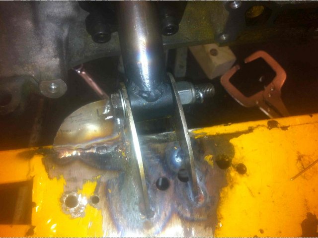
Here's the final mount with gusset
So, before I welded in the top chassis strengthening rail, i figured i should finish the bottom mount off first - the chassis rail will make access
for welding a little difficult.
.
Here it is with the gusset, and split pin through the bolt for extra safety.
Description
When all you have is a hammer, everything around you is a nail.
www.furyrebuild.co.uk
|
|
|
MRLuke
|
| posted on 2/7/12 at 12:35 PM |
|
|
Thats a really tidy job there
|
|
|
FuryRebuild
|
| posted on 2/7/12 at 01:05 PM |
|
|
Thanks very much. I'd say it probably took me a day all in. My welding is much better now than the first time I build the car.
When all you have is a hammer, everything around you is a nail.
www.furyrebuild.co.uk
|
|
|
MikeRJ
|
| posted on 2/7/12 at 02:30 PM |
|
|
Plenty of production cars use a similar design, but they have an awful lot more rubber in the mounting bush. With the very small bushes used and the
minimal clearance between the bush tube and the mounting bracket on the chassis I suspect that might transmit a fair bit of vibration.
|
|
|