geedle
|
| posted on 4/2/23 at 05:06 PM |

|
|
Saturn wishbones
Hi,
I've made up wishbones for my Haynes/Saturn build. The rear hub/wheel is very much on the wee - something is wrong.
Bottom Rear Wishbones
This
suggests that the total length of the lower wishbones should be 395.8mm. In the Saturn book, no measurement is given for the jig plate. If you
assume that it is the same size as the Haynes book, then that'll give a lower wishbone length of 415mm (465 - 50 for the two 25mm box sections).
This is nearly at 20mm difference. Which one is right?
Upper Rear Wishbones
The plate size is given as 300mm, but nothing is build referencing the right hand end of that plate. I built mine to the spec shown in the link
above.
Any ideas?
Many thanks, Geedle.
|
|
|
|
|
geedle
|
| posted on 12/2/23 at 05:12 PM |
|
|
So I'm still struggling with the rear suspension measurements. I've got massive positive camber. I've broken down my measurements a
little more to see if anyone has any insight as to where I've messed up.
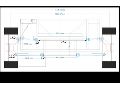 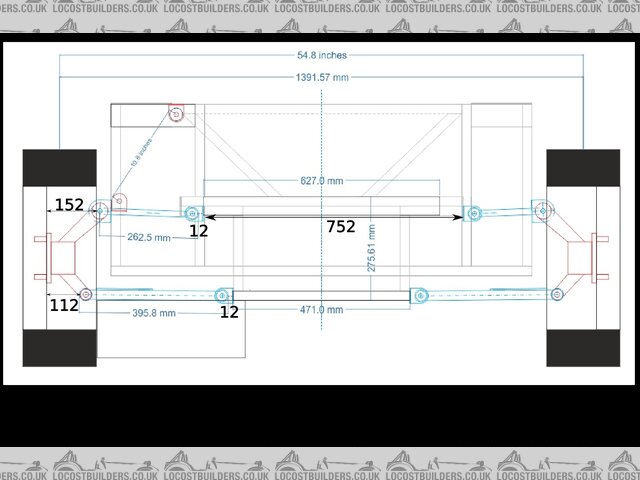
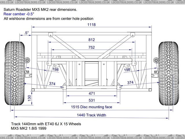
Saturn Rear Suspension
Above I've added the missing measurements.
So for the top wishbones, from between the wheel mounting faces:
154 + 262.5 + 12 + 752 + 12 + 262.5 + 154 = 1609
And for the bottom:
112 + 395.8 + 12 + 471 + 12 + 395.8 + 112 = 1510.6
Giving a difference of 98.4, which would explain my camber issues. I guess that that value looks about right for my current camber.
Breaking down the measurements:
- 152 - my measurement from the rear hubs
- 112 - my measurement from the rear hubs
- 262.5 - from the diagram
- 395.8 - from the diagram
- 12 - measured gap between wishbone and RS7/RS7a
- 752 - external separation of RS4 and RS5 as given in the Saturn book
- 471 - from the diagram, unchanged from the Haynes book
- 627 - it is a bit unclear what this is on the diagram. I think it is the measurement from the outer edge of RS4 and the centre of the hole for the
diff mounts.
Much appreciated, Geedle.
|
|
|
Prof_Cook
|
| posted on 12/2/23 at 09:12 PM |
|
|
Upper wishbone mounts inter-rail dimension.
I assume the original measurements on the drawing are correct? and you have mirrored the measurements to the right hand side of the drawing and built
the wishbones to those measurements? So I measured the dimension between the upper wishbone mounting points by "scaling" from the drawing
which gives me 698mm for the inter-rail dimension between the upper wishbone mounts rather than 752mm.
Also (assuming the drawing is not distorted) and is being viewed from the rear of the frame, then when I hold a ruler up to your drawing on my screen,
the upper right wishbone is shorter than the upper left wishbone.....which appears to be confirmed by measuring from the centre vertical datum which
seems to show the upper right wishbone mounting point is further from the vertical datum than the left upper wishbone mounting point (which it would
have to be if the upper right wishbone was shorter).
Hope you find the solution.
[Edited on 12/2/23 by Prof_Cook]
[Edited on 12/2/23 by Prof_Cook]
|
|
|
Prof_Cook
|
| posted on 12/2/23 at 09:19 PM |
|
|
Revised distance between upper wishbone mounts
Reverse calculating....
Assume required total measurement for top wishbones is 1511mm (rounded from your 1510.6) to be same as lower wishbones.
Top mounts separation = 1511 - (152+262.5+12+12+262.5+152) = 658mm remaining rather than 752mm which is a difference of 94mm
If the mounting face distance is 154 rather than 152 then revised calculation is 1511 - (154+262.5+12+12+262.5+154) which is 654mm rather than 752mm
which is a difference of 98mm which could be coincidental as it appears to be the same as the number you are looking to have explained.
[Edited on 12/2/23 by Prof_Cook]
[Edited on 12/2/23 by Prof_Cook]
|
|
|
Prof_Cook
|
| posted on 12/2/23 at 09:38 PM |
|
|
The shorter upper right wishbone (from the drawing ) comes out at about 188mm rather than 262.5mm a difference of 74.5mm
|
|
|
geedle
|
| posted on 13/2/23 at 08:44 PM |
|
|
The external separation of RS4 and RS5 is wider than the Haynes book because of the ears on the MX5 diff. The bush centres on the diff are exactly
600mm apart, but with the bushings the total width is 690mm. Add in the width of RS4 and RS5 (25mm + 25mm) gives 740mm. With a little room for flex
in the bushes, 752mm, as given in the Saturn book rather seems like a sensible minimum.
The diagram came from here. The diagram is visibly different left to right in a
way that is clearly not correct. Given the absence of any measurements on the right of the diagram, I used the ones of the left and mirrored to the
other side as you say. This may have been a mistake. I am assuming that the two wishbones are supposed to to be the same. The frame is also
different, but no mention of that is made anywhere else.
This suggests that the top wishbones should only be about 200mm.
Using 200mm in place of the 262.5, we get:
154 + 200 + 12 + 752 + 12 + 200 + 154 = 1484mm for the total upper width, which I guess is close enough to the lower measurement of 1511mm. That is
27mm difference, or 13.5 on each side. Is that close enough? Or even deliberate?
Thank you for talking this through with me - I'd hit a dead end with it.
Geedle.
|
|
|
Prof_Cook
|
| posted on 13/2/23 at 09:04 PM |
|
|
Glad to be of any help. I'm in a slightly different boat with my "challenging project" to build a single seater. So your query was very
illuminating and I will be using a similar process to get to wishbone dimensions once the frame and wishbone locating lugs are welded up. I'll
be using threaded inserts at end of wishbones and ensuring there is a good depth of insert screwed in but still allow a few mm of movement to
accommodate any minor error in my calculations.
[Edited on 13/2/23 by Prof_Cook]
|
|
|
Prof_Cook
|
| posted on 13/2/23 at 09:21 PM |
|
|
Another revised calculation
Assuming 752mm is your total top rail width then
1511 - (752+154+12+12+154) = total for 2 upper wishbones = 427mm
So each upper wishbone would be 427/2 or 213.5mm long to align with the bottom wishbones, but:
Assuming each upper wishbone is 13.5mm shorter at 200mm then you will have negative camber - which is good according to the below linked page:
https://web.archive.org/web/20151210154450/http://www.240edge.com/performance/tuning-camber.html
I am designing for negative camber but degree still to be determined - which is another reason for using adjustable inserts on my (still to be made
up!) wishbones.
|
|
|
geedle
|
| posted on 18/2/23 at 06:54 PM |
|
|
Hopefully I'll get back to it this week. I'll post back my findings!
|
|
|
Half Finished
|
| posted on 3/5/23 at 05:43 AM |
|
|
Did you have any luck with this? I'm at this stage now too.
I'm starting to remake the drawing in your OP.
|
|
|
Half Finished
|
| posted on 6/5/23 at 11:27 AM |
|
|
I've modified some CAD drawings now, I've just posted in my build thread.
Does this make sense at all?
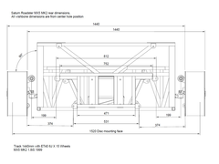 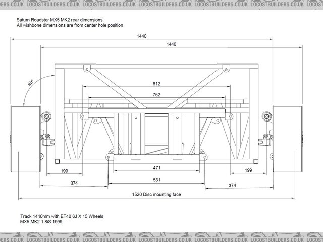
Description
CAD File
|
|
|
Prof_Cook
|
| posted on 6/5/23 at 11:48 AM |
|
|
Hi. Only got my phone with me at the moment, but looks good.
But can't see any negative camber (tyres at 90 degrees to frame verticals) so assume you have adjusters in the wishbones to "dial in"
your desired camber?
[Edited on 6/5/23 by Prof_Cook]
|
|
|
Half Finished
|
| posted on 6/5/23 at 07:14 PM |
|
|
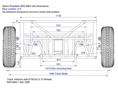
Good point regarding camber! It looks like -0.5° camber is recommended for the rear and that's pretty close to the stock MX5.
Keeping the same track width, the axle width works out to 1515mm.
I also had the wrong ride height, so I've adjusted it to 130mm too.
Description
|
|
|
Prof_Cook
|
| posted on 7/5/23 at 06:37 AM |
|
|
Obviously I don't know your thoughts and I am still to design my wishbones. I am thinking of -1.5 degrees camber (with car suspension at ride
height ) for the rears although solely based on what I have seen here:
https://bofiracing.co.uk/blog/mazda-mx-5-wheel-alignment-specs-for-race-track-and-fast-road/
[Edited on 7/5/23 by Prof_Cook]
|
|
|


