hellbent345
|
| posted on 10/7/08 at 09:40 PM |

|
|
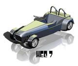
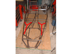
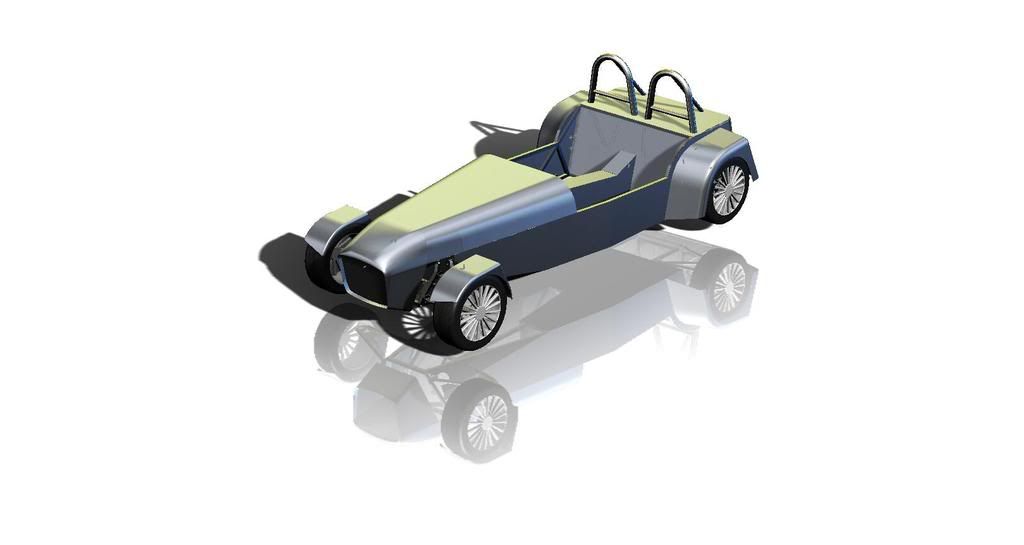
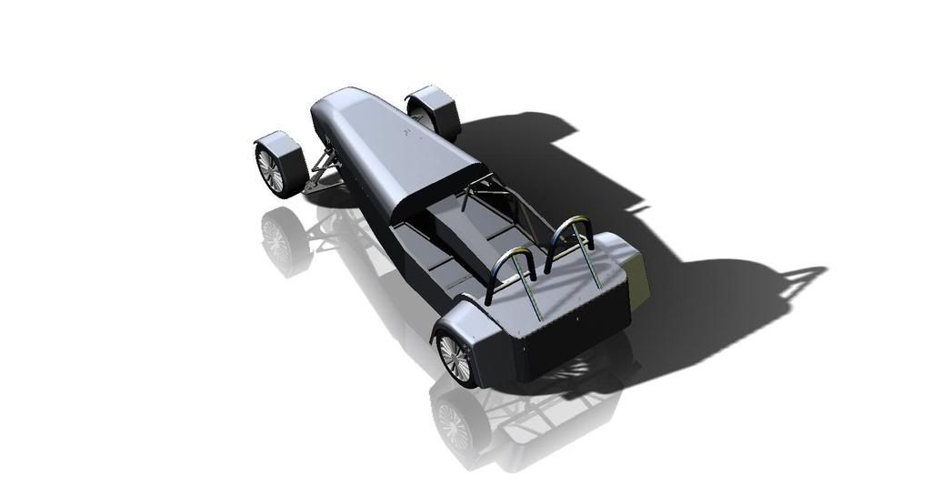
chassis design
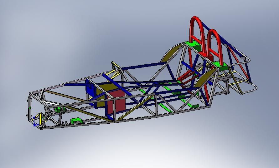
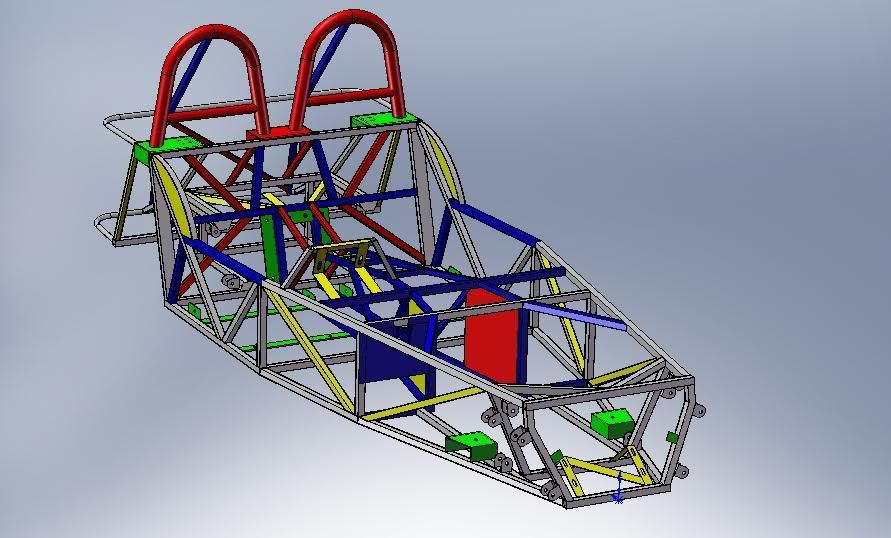
finally got round to posting up my solidworks designs of my chassis! i changed a lot! can anybody see any glaring mistakes? i prefer twin rollbars so
had to change the back portion to support that, is the redesign sufficiently strong? alos added a trany tunnel similar to a westfield to accomodate
mt75 box (the westy design i used incorporated the mt75) also a diagonal rear crossbar for rear impact protection as i had to widen the ditance
between the rear vertical tubes, and i few other mod i cant remeber, what do u all think? red is added, blue is modified, yellow is modified from the
book measurements simply to fit, and green is stuff i need to change later
thanks
al
|
|
|
|
|
big_wasa
|
| posted on 10/7/08 at 09:51 PM |
|
|
just an idea but I like a second rail the full width of the car for the roll bar mounts ect
 
|
|
|
blakep82
|
| posted on 10/7/08 at 09:52 PM |
|
|
i'm not sure if its worth some kind of triangulation under the seats? i forgot what the book chassis' like. just seems the floor of the
chassis is very square
________________________
IVA manual link http://www.businesslink.gov.uk/bdotg/action/detail?type=RESOURCES&itemId=1081997083
don't write OT on a new thread title, you're creating the topic, everything you write is very much ON topic!
|
|
|
CaptainJosh
|
| posted on 10/7/08 at 09:57 PM |
|
|
quote:
Originally posted by big_wasa
just an idea but I like a second rail the full width of the car for the roll bar mounts ect
I second that!
|
|
|
indykid
|
| posted on 10/7/08 at 10:01 PM |
|
|
i'd run the back braces for the roll hoops down to the back corners of the chassis onto a plate in the rounded corner.
also i'd swap the top braces in the engine bay for y braces running to the top of the fu tubes. as they are, they do very little as the top side
rail will offer no support.
|
|
|
hellbent345
|
| posted on 10/7/08 at 10:09 PM |
|
|
yeh the second rail idea is a good one i was thinking that the chassis plate were a little flimsy! triangulationwise i dont know what is needed both
the book chassis i was looking at and the westfield drawings dont have any triangulation under the seats but i agree it would seem like it needs it
there... good idea about bringing the stays down to the bottom, only problem i could think of is would the angle then be a little shallow-also the
bars might then encroach on the fuel tank...? what do you mean about y braces?
|
|
|
big_wasa
|
| posted on 10/7/08 at 10:15 PM |
|
|
Not a Y brace but better than the short braces you have.
The top two braces that run from your bulk head to part way down the top rails.
|
|
|
big_wasa
|
| posted on 10/7/08 at 10:22 PM |
|
|
front rack mounts will need more bracing aswell
|
|
|
andrew-theasby
|
| posted on 10/7/08 at 10:24 PM |
|
|
If i had some pictures id post them, but ive just done my roll bar exactly as the suggestions, seems plenty strong enough. Mine bolts in, and your
right it does foul the fuel tank but i just cut two scallops out of it and welded plates back in to clear it. With your welded in rollbar, can you
actually get a fuel tank into position? I didnt like the idea of going back to the top rail without putting more triangulation in (looking sideways
on the car) from roll bar base straight back to top rail where the rear stay mounts to stop it all collapsing backwards in an accident, but then that
would serverely restrict the size of tank you could get in.
|
|
|
indykid
|
| posted on 10/7/08 at 10:55 PM |
|
|
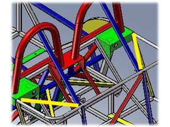
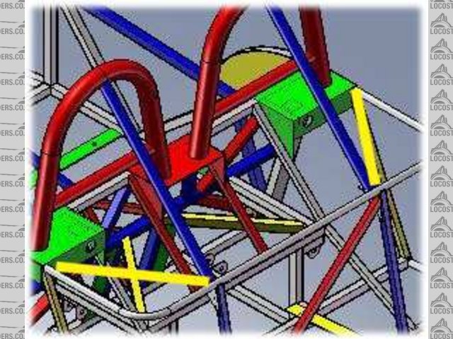
this is what i mean.
tom
Rescued attachment y brace.jpg
|
|
|
tomblyth
|
| posted on 11/7/08 at 05:36 AM |
|
|
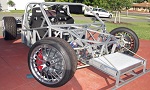
my mk does'nt have all that extra triangulation!
(http://www.locostbuilders.co.uk/photos.php?action=showphoto&photo=2DSC00111.JPG)
I dont think it needs it , if you keep adding bars and all that extra weight you might as well drive an off the shelf car and if weight is not an
issue and your after better crash protection drive one of these
(http://www.locostbuilders.co.uk/photos.php?action=showphoto&photo=well%20build%20will%20survive%20a%20crash.jpg)
i hear there good in an impact but heavy on fuel.
|
|
|
Ivan
|
| posted on 11/7/08 at 07:43 AM |
|
|
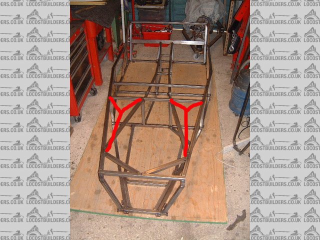
^^^ I agree - however if you are going this route I would add additional triangulation for the Roll Bar bracing as shown in yellow below.
Of course if the chassis is fully braced then you might get away with 19mm steel instead of 25mm - however you would need to get a profesional FEA
done to check
Description
|
|
|
hellbent345
|
| posted on 11/7/08 at 08:32 AM |
|
|
thanks for the ideas, what is the average weight of a chassis, does anyone know? ive done an analysis on what ive got so far and it wil weigh around
100kg (103) is that hefty? also that diagonal bracing for the rollbar is a good idea i may well add that , the y bracing looks interesting, but ill
run an fea to see what tubing i can get down to safely in places to lighten er up, and see if that will really make much of an impact (the top of the
engine bay as it is, is almost exactly the same as the top of a westfield bay)
|
|
|
indykid
|
| posted on 11/7/08 at 09:43 AM |
|
|
search for posts by cymtriks on fea. liam also did some fea on his chassis and both came to the asme conclusion. the R tube is very important to
torsional rigidity of the chassis.
following a manufacturer's example doesn't neccesarily mean it's correct. an MK is missing all sorts of tubes in the engine bay that
would probably help.
tom
|
|
|
scootz
|
| posted on 11/7/08 at 11:03 AM |
|
|
Are there any suppliers who offer heavy guage roll hoops, or do you have to commission your own?
|
|
|
hellbent345
|
| posted on 11/7/08 at 12:31 PM |
|
|
im going to have to get them made i think as id rather know that my head isnt going to become closely aquainted with the ground if the worst happens!
so ill be getting in touch with some people and getting it done 1 off! spensiveeee
|
|
|
Cobra289
|
| posted on 13/7/08 at 06:24 PM |
|
|
hellbent345
Well done!
It looks pretty nice in SW.
I have done a comparable design in SW and the weight [without the foot well,plates] is 66Kg.
How much is yours?
Watch out for the suspension components, that will make or kill your car.
Regards,
Cobra289
|
|
|
MakeEverything
|
| posted on 1/8/08 at 09:39 PM |
|
|
quote:
Originally posted by hellbent345
thanks for the ideas, what is the average weight of a chassis, does anyone know? ive done an analysis on what ive got so far and it wil weigh around
100kg (103) is that hefty? also that diagonal bracing for the rollbar is a good idea i may well add that , the y bracing looks interesting, but ill
run an fea to see what tubing i can get down to safely in places to lighten er up, and see if that will really make much of an impact (the top of the
engine bay as it is, is almost exactly the same as the top of a westfield bay)
If you cant lift it off the ground completely with one arm, by standing in the middle, then its too heavy. Looking at the above discussions,
triangulation isnt necessary inder the seat, as the "Squares" wont flex or become trapezoid shapes. The geometry on the car is in a
different plane ie. Forwards and sideways, or in a twisting motion. Triangulation here wont stop twist. Dont underestimate the strength of 8guage
25mm box, or indeed a descent weld. 
Kindest Regards,
Richard.
...You can make it foolProof, but youll never make it Idiot Proof!...
|
|
|
hellbent345
|
| posted on 14/8/08 at 09:43 AM |
|
|
8 guage :O! ive done a bit more on the design taking quite few cues from the caterham rs (V8) the chassis weighs a bit over 100kg cobra, i think i
shelled all the members but i cant be sure so thick members may be part of the cause! i recon if i lifted with my knees i could prob lift up 100kg
with one hand but only for a split second, does that count? ill post up the pics of the design, itll be mainly bodywork im fraid!
al
|
|
|
hellbent345
|
| posted on 14/8/08 at 09:50 AM |
|
|
|
|
|
Cobra289
|
| posted on 14/8/08 at 09:46 PM |
|
|
quote:
Originally posted by hellbent345
[img]
Nice surface work.
I am fighting with the nose cone.
Regards,
Cobra289
|
|
|
Liam
|
| posted on 15/8/08 at 11:27 AM |
|
|
I had a go at a nosecone ages ago. See here...
http://www.locostbuilders.co.uk/viewthread.php?tid=37702
It was really just to learn a bit about using the 3D surface features with a minimal number of profile sketches. As such, it's dimensionally
reasonable but certainly not an 'elegant' use of Solidworks. I had all sorts of problems thickening to solids and it's ended up
with over 30 unmerged solid bodies etc etc. Anyway it served its purpose and you can get it at that link.
I guess the 'proper' accurate way to do it would be painstakingly measuring up the real thing and building up cross section profiles, say
every inch, the lofting between them, shelling, trimming etc - i.e. the computer version of building a wooden mould for replica bodywork. Or using a
package more geared for abstract 3D shapes.
Liam
|
|
|
hellbent345
|
| posted on 15/8/08 at 10:32 PM |
|
|
yup that would be the way to do it, i lofted in rathr larger stages with guide curves and it didnt give me exactly what i wanted, but near enough to
look alright, that linky was good when im next on my cad computer ill download them iles, i have my nosecone file cobra if u want it? its rather rough
but ur welcome if u want it (2008 file, or parasolid) im still at the stage of not knowing how front uprights work so i cant design them, i know about
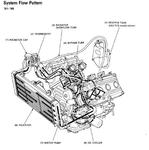
the cortina upright part, but i dont know how the wheel then bolts onto the shaft, plus people say shaft through bearing is beter than some other
method but i dunno whats up! anyone got an exploded drawing of a fully assembled front upright, bearing hubs and all? thanks for kind words!
alan
|
|
|
Cobra289
|
| posted on 17/8/08 at 01:13 PM |
|
|
quote:
Originally posted by hellbent345
yup that would be the way to do it, i lofted in rathr larger stages with guide curves and it didnt give me exactly what i wanted, but near enough to
look alright, that linky was good when im next on my cad computer ill download them iles, i have my nosecone file cobra if u want it? its rather rough
but ur welcome if u want it (2008 file, or parasolid) im still at the stage of not knowing how front uprights work so i cant design them, i know about
the cortina upright part, but i dont know how the wheel then bolts onto the shaft, plus people say shaft through bearing is beter than some other
method but i dunno whats up! anyone got an exploded drawing of a fully assembled front upright, bearing hubs and all? thanks for kind words!
alan
It would be nice to get the nosecone. I use SW2007 I prefer to have as 2007 but probably would be impossible, a parsolid would be OK.
Our Locost design has the dimensions equivalent to the Chris Gibs [Haynes] book and I did try the cone of the mentioned thread but that cone shims to
be for an standard chassis.
Check my Nosecone without any measured dimension but just an space match.
At the second picture you can see the downloaded nosecone that differs a lot.


Regards,
Cobra289
Regards,
Cobra289
|
|
|
Doug68
|
| posted on 17/8/08 at 02:05 PM |
|
|
Why do people always want to do this?
wouldn't it be easier just to remake the tie road the right length?
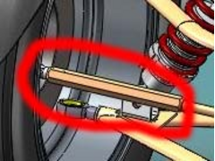 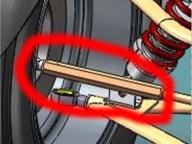
Rescued attachment Untitled-1.jpg
Doug. 1TG
Sports Car Builders WA
|
|
|