
Gear Linkage Pivot
Avoneer - 25/9/05 at 02:34 PM
Hi,
Trying to think of an easy neat solution to connect the pushrod from my paddle shift to the pushrod connected to the gear lever selector on the
bike.
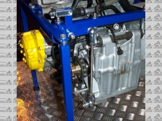
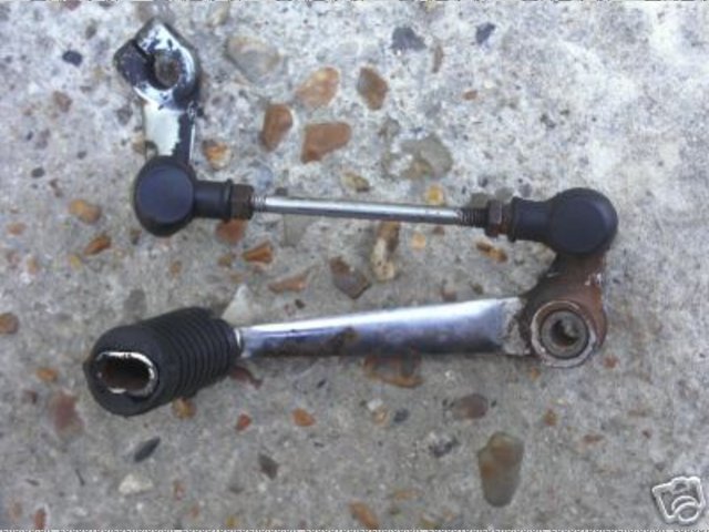
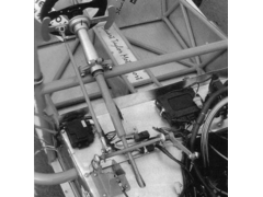
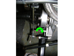
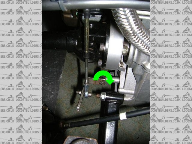
Best example I can find and closest to what I am looking for is from Ox's photo archive.
Anyone any ideas or suggestions?
Cheers,
Pat....jpg)
Avoneer - 25/9/05 at 02:35 PM
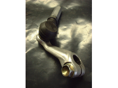
Just thought though, if I could buy a steel gear arm, I could do it like this:

Rescued attachment avon_gear_link_2.jpg
Avoneer - 25/9/05 at 02:37 PM
Can you buy steel gear lever selectors separately so I can extend it and have the pushrod vertical?
Pat...
Avoneer - 25/9/05 at 02:38 PM
Gear selector like this:
Rescued attachment Extended arm.jpg
Avoneer - 25/9/05 at 02:39 PM
If I could get the thing vertical, it could pivot easily on the shoulder of a bolt between two brackets.
Pat...
OX - 25/9/05 at 02:39 PM
i did the busa this way as i wasnt happy with the way i did the r1

but the other picture you posted looks realy neat 
Avoneer - 25/9/05 at 02:50 PM
Hi Ox,
That's the aprillia bit is it?
Does it just pivot on a bolt?
If I can extend the gear lever selector (by hopefully buying a steel one) I can do it like that.
Cheers,
Pat...
Avoneer - 25/9/05 at 02:52 PM
That's not mine in the blue frame Ox!
Pat...
tadltd - 25/9/05 at 03:16 PM
What about welding an extension arm onto your selector lever?
andrew.carwithen - 25/9/05 at 03:31 PM
What selector lever have you got at the mo' Pat?
There were two types fitted to the early blades.
893cc use a simple alloy lever which is approx 5" long. Could you not drill out the toe peg and replace with a rose joint?
919cc blades use a 'rear set' type linkage (as the gearbox runs in the opposite direction to the 893cc) with a short stubby selector.
(I'm not sure if this is alloy or mild steel but it seems heavier than the alloy one, so may be able to extend it?)
I've got it fitted to my engine, so if I get chance, I'll nip out to see if its magnetic or not!
Andy.
Winston Todge - 25/9/05 at 03:35 PM
Where can you buy ball joints or pivots like those on your pictures OX and Pat? How much?
Ta,
Chris.
Avoneer - 25/9/05 at 04:22 PM
My arm isn't long enough and is a small alloy item with a kink in it. I could extend it, but I can't weld alloy!
It just needs a straight piece of flat bar to extend it.
I'll get a pic shorlty, but F1 is about to start.
Pat...
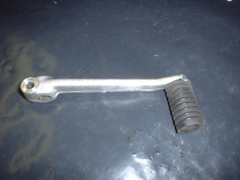
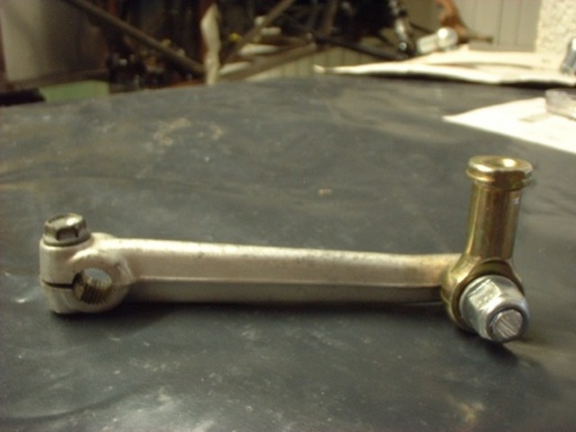
Avoneer - 25/9/05 at 04:40 PM
This is my link, but it just 'aint long enough.
Pat...
Rescued attachment Arm.JPG
Avoneer - 25/9/05 at 04:42 PM
Bloody 'ell, that pic came out well.
Pat...
tadltd - 25/9/05 at 05:05 PM
Chris - I can do those ball joints for you, just need to know how big. They come with ball & socket.
Avoneer - 25/9/05 at 06:51 PM
This is the older blade one - might do the job.
Can you weld alloy?
Pat...
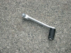
Rescued attachment ce_1_b.JPG
andrew.carwithen - 25/9/05 at 06:56 PM
So is that one still not long enough, then, Pat? (That's the one I thought you may be able to drill out the rubber covered peg and replace with a
ball or rose joint.)
Andy.
Avoneer - 25/9/05 at 07:08 PM
Might be.
I've not got one to measure though.
Can you tig ali bar to alloy?
Pat...
andrew.carwithen - 25/9/05 at 07:28 PM
quote:
Originally posted by Avoneer
Might be.
I've not got one to measure though.
Can you tig ali bar to alloy?
Pat...
Dunno...not too hot on welding techniques..Others to answer that one!
However, I've got the same gear lever in the garage somewhere.
I'll find it tomorrow and measure it.
Do you know what length you actually need?
(I bought both types of lever on ebay (do a search for 'fireblade'
Expect to pay about a tenner each inc. postage.
Andy.
Avoneer - 25/9/05 at 08:54 PM
Hi Andy,
This makes a change me asking for advice!
I've just won one of the longer ones on ebay for �4.99 so will compare the two when it lands and then work out what to do.
Just go to work out the top pivot/arm now and how best to make it slip/twist.
Pat...
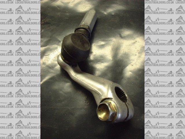
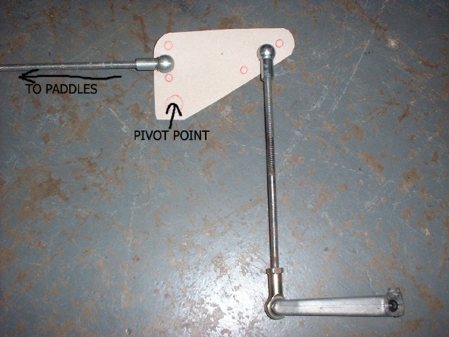
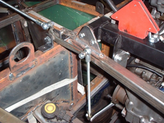
Avoneer - 25/9/05 at 09:40 PM
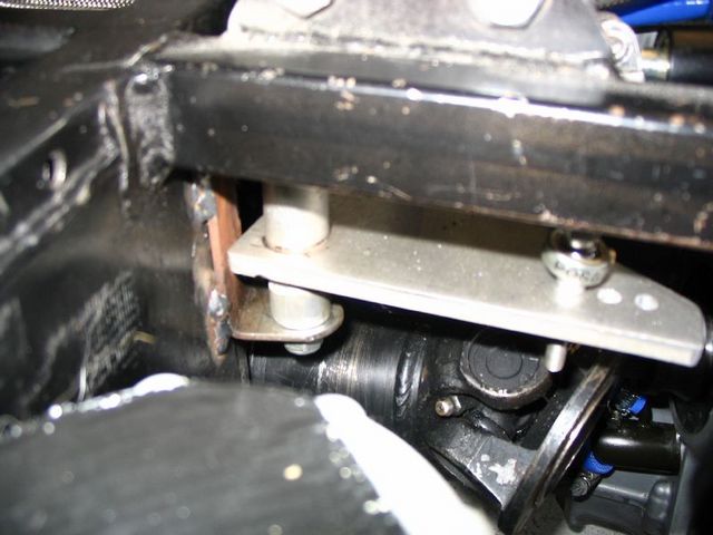
Right, after a waffle with Ox (cheers), I'm now looking at something like this which looks ideal for the top mount and would be dead easy to
mount with two lugs and a bolt through the lot.
Pat...
Rescued attachment top rocker.JPG
Avoneer - 25/9/05 at 09:42 PM
Obviously I'd loose the two rose joints, small bar between them and the splined gear lever bit.
Pat...
ReMan - 26/9/05 at 10:11 AM
The lever I used for my lower link was a steel one I picked up from a breaker.
It started life about 6" long, bendable and weldable to shape, see pic here (just)
http://www.locostbuilders.co.uk/viewthread.php?tid=31407
Avoneer - 26/9/05 at 11:09 AM
Any idea what bike it came from Mr Rehman?
Thanks,
Pat...
ReMan - 26/9/05 at 11:44 AM
quote:
Originally posted by Avoneer
Any idea what bike it came from?
Pat...
The honest answer is no, but I would guess a small Honda 125 type thing, though i'm sure there are many bikes with the same spline
pattern............
Spyderman - 26/9/05 at 01:15 PM
Avoneer, why do you want a longer lever for the gearbox?
Any change in lever throw can be done by using different lengths on an "L" shape lever as in your 1st picture.
All you need to do is work out how far you want the paddle shifter to move. Then find out how far the gear selector arm moves.
If the pushrod from your paddle-shift is moving 5mm and you need the selector to move 25mm, all you need is a 5:1 ratio on "L" lever. So an
"L" lever with pivot to short end of 15mm and pivot to long end of 75mm would give travel required.
The "L" lever could very easily be made from 3mm steel.
Hope I haven't misunderstood your question!
Terry
andrew.carwithen - 26/9/05 at 03:43 PM
Pat,
I've measured the length of the alloy gear lever you won on ebay and it is 115mm (4 1/2" between centre of splined hole and centre of
toe-peg.
(I've also got the later rear-set type linkage if you want me to measure the 'L' shaped lever of that?)
Andy.
Avoneer - 26/9/05 at 03:49 PM
Hi Spidy, no, you haven't misunderstood the question.
I fogot to say that the because the original one is too short, the rod from the gear selector on the engine would have to be at about a 60 degree
angle to clear the prop, so a longer arm would let this push rod sit vertically which would make everything else easier so it wouldn't have to
all be on an angle like Ox's first top pivot.
I can then use the "L" to adjust as necessary with a much better angle for both rods.
Hope that makes more sense now,
Pat...
Avoneer - 26/9/05 at 03:51 PM
Cheers Andy.
That brings the first (lower) joint to just where I want it.
Just the top one to finalise now.
Pat...
billy - 26/9/05 at 05:08 PM
That lever comes from a yamaha rd 350lc im sure of it, ive owend lots of those bikes
ChrisGamlin - 26/9/05 at 05:18 PM
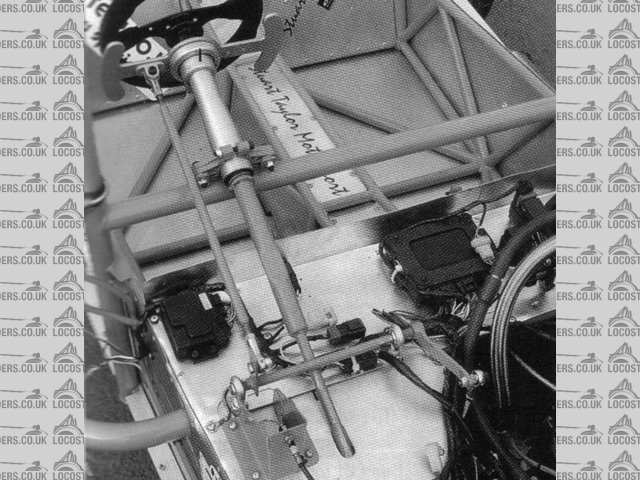
Pat, if you get really stuck, you could try speaking to Westfield
The lever they sell as part of their gearchange kit is about the size you need because it too uses a vertical rod so needs the length to clear the
prop. You can see it in the middle of the pic here, they might sell you one on its own maybe?

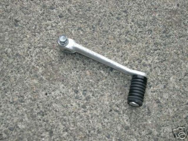
Avoneer - 27/9/05 at 06:34 PM
Cheers Chris, but the one that arrived today is perfect.
This is what arrived:

Rescued attachment 1.JPG
Avoneer - 27/9/05 at 06:35 PM
So I cut of the flange holding the rubber on and removed the rubber.
Then tapped the bar:
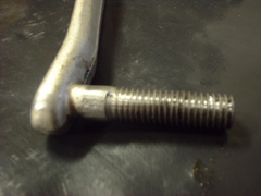

Rescued attachment 2.JPG
Avoneer - 27/9/05 at 06:38 PM
Slid my rose joint on the threaded stub and put a nut on it.
Bottom mount sorted - dead easy and perfect for the job, and if the stub ever snaps/bends, I can just cut it off and drill throught the gear selector
lever and bolt the rose joint on:
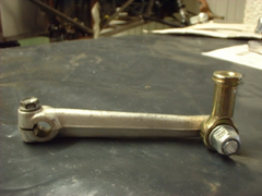
Rescued attachment 3.JPG
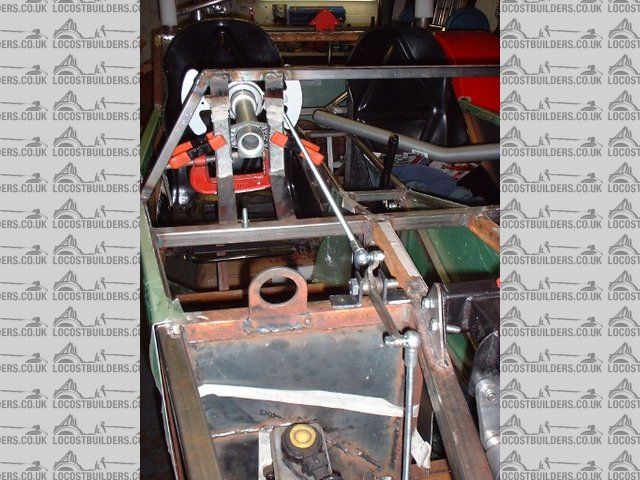
Avoneer - 27/9/05 at 06:40 PM
Just the top bit to think about again.
Simplist thing I can think of is using 3mm steel plate looking like the following pic. and held in place with two lugs on the chassis and a bolt
through the bottom pivot hole.
Anyone any ideas as to what type of bearing surface I can use on this pivot point?
Pat...

Rescued attachment 4.jpg
Avoneer - 27/9/05 at 06:41 PM
Obviously, the lower gear seletor lever will be a right angles pointing into the picture.
Pat...
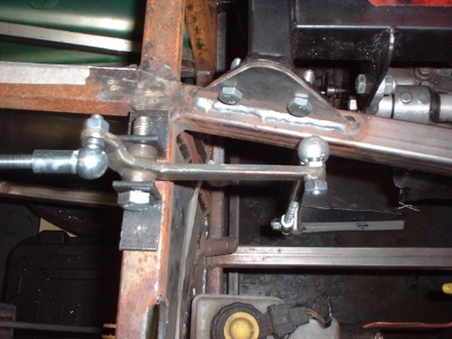
ChrisGamlin - 27/9/05 at 07:00 PM
Hi Pat
It looks like you need similar to what Ive got mounted horizontally for my R1 rocker.
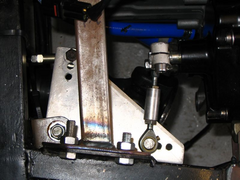
Gearchange rocker top

Gearchange rocker drivers side
As you can see, its made of two bits of ally, a bit of solid bar about 5cm long thats been drilled in the lathe to make the pivot bush, and a
triangular piece of thick plate with a hole drilled in one corner for the bar to pass through, plus obviously small holes for the rod ends to bolt to.
I was intending on eventually making another one with a couple of bearings in it, but this works absolutely fine pivoting on a bit of 10mm steel bar
with some copperslip in there, no slack at all and silky smooth. The only slight issue is that you'll need to get your welder mate to TIG the two
bits together unless you can be fancy and make it a press fit.
Avoneer - 27/9/05 at 07:36 PM
Hi Chris.
Yep, that's almost what I'm looking for, although the traingular plate will be vertical above and just in front of the pedal box.
Does it just pivot on the solid bar with a 10mm hole through the centre of it and a piece of threaded rod with a nut top and bottom?
Cheers,
Pat...
ChrisGamlin - 27/9/05 at 07:43 PM
Yep, the steel pivot bar is tapped top and bottom and tightened up until the steel bracket on the chassis just starts to close up, stopping any
significant vertical float without binding it up.
To do it this way you need to have a long pivot to spread out the load, otherwise it could twist or wear quickly. Because the pivot is about 5-6cm
high, the tolerences dont have to be to the nearest thou' in order to get a nice slack free pivoting action, although you'd want to do it in
a lathe with a decent drill bit obviously.
Avoneer - 27/9/05 at 07:49 PM
Cheers Chris.
Will have to ponder on this some more.
I'm liking the idea of a press in bearing of some kind.
May just let it pivot on the shoulder of a 12.9 bolt yet!
Did you sell your seats by the way?
Cheers,
Pat...
ChrisGamlin - 27/9/05 at 08:03 PM
Yep, sold them to stevebubs.
Avoneer - 27/9/05 at 08:06 PM
Oh well, missed a good pair there!
Pivot - how about two rose joints mounted on a plate with 5mm gap between them with the plate between them and a piece of threaded rod through both
centres bolted on each side?
Pat...
ChrisGamlin - 27/9/05 at 08:20 PM
quote:
Originally posted by Avoneer
Oh well, missed a good pair there!


I have visualisation of what youve described but I might be wrong, so fancy drawing a diagram?
Avoneer - 27/9/05 at 09:20 PM
Hope this makes sense:
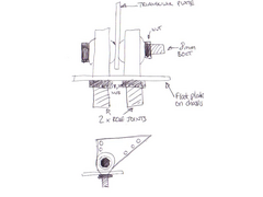
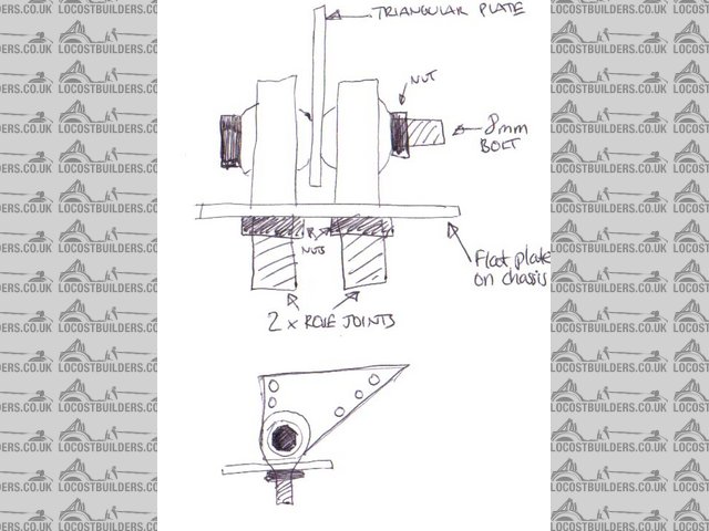
Rescued attachment 1.jpg
ChrisGamlin - 27/9/05 at 09:42 PM
Hmm, Im not sure that will work too well to be honest, rod ends wont actually give you a movable bearing surface when mounted like that, the plate
will just rub against them which is not how they are designed to work, and the plate will want to twist on the pivot when you put force through it
because of its lack of thickness not spreading out the twisting forces.
ChrisGamlin - 27/9/05 at 09:49 PM
Actually looking at it again if you clamp it all up tight I guess the rod end balls will rotate and give you a decent bearing surface. I still think
the plate will try to twist too much and it will gradually start moving in the way Ive described above, rather than the rod ends giving the rotational
movement.
If you mounted the rod ends further apart and made up a plate with a much thicker pivot length like mine, then that should work OK though, as the
wider surface will spread out the load much more.
[Edited on 27/9/05 by ChrisGamlin]
Avoneer - 27/9/05 at 11:00 PM
Aaaaaaa, so that's why ST use two rod ends almost 12" apart!
All makes sense now!
Ok, both rod ends far apart with solid 12mm bar in between them will a 8mm threaded bit on each end that goes through the rod ends.
Triangle plate then welded to middle of the bar.
That should do the job.
Watch this space.
Pat...
Avoneer - 29/9/05 at 11:07 AM
How about using a wishbone eye and polybushes between two lugs and the arms welded on to the eye?
That would be cheap and simple???
Pat...
ChrisGamlin - 29/9/05 at 05:19 PM
Poly bushes dont really give you a very friction free movement, OK for suspension but probably a bit sticky and imprecise for the gearchange. It may
also be too flexible side to side still - think of a live axle'd car without a panhard rod to picture what I mean....
What you could do is get a decent bearing to go inside the widhbone eye. I bought two bearings for my steering column that were IIRC about 20mm wide
wth a 1" OD, 5/8" ID. one of those pressed into a 1" ID wishbone type eye pivoting on a 5/8 steel pivot would do the job well, the
bearings were only around �5 each ISTR so it shouldnt cost a lot to do it.
Chris
Winston Todge - 29/9/05 at 08:16 PM
This is a very interesting thread as I'm planning on fabbing up a paddle change, obviously minus the CNCed ST paddles as I think they'll be
a little more than I can afford!?
Chris.
Avoneer - 29/9/05 at 10:31 PM
Working on an easier and cheaper solution now.
Found a good place for the M8 sphericals, although not as posh as OX's, more like the gold ones I am using.
Watch this space.
Pat...
tks - 1/10/05 at 01:53 PM
i have made an gear switch system useing an electril RC Servo..
from the quarter scale section.
does anyone have ideas...if there would something an bit powerfull for it?
what would/could happen if i take out the return spring? from the gearbox..??
how much room do we have on the gear linkage, i mean what if the lever doesn't come in his rest position by an couple of degree does the
lever/box than damage extra?
how fragile is the box?
what happens witht he box if you drive normally on your bike...
but in every gear you push the lever, the bike enters gear..and you stay and you let the leaver in that pos. for 1 second...
would it sacrafise? would it become damaged? the forks??
Tks
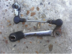
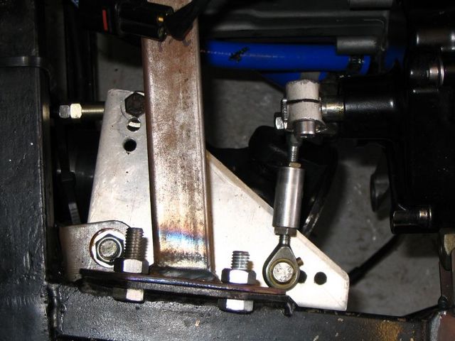
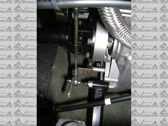
Avoneer - 6/10/05 at 09:28 PM
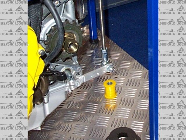
Update:
I am using this arm and all seems well, although it's a bit hard to pull the paddles.
Maybe because I've nothing to pull against like the steering wheel.
Anyone know how to mod the leverage to make the paddles lighter, but with the same movement at the gearbox end.
Pat...

Rescued attachment Top Arm.JPG
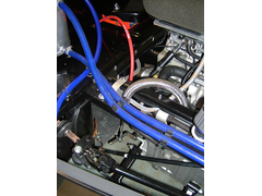
Avoneer - 6/10/05 at 09:29 PM
Another pic:
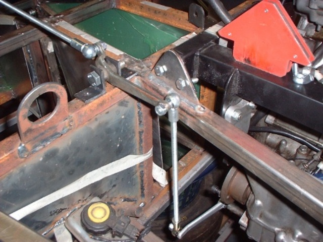
Rescued attachment Top Arm2.JPG
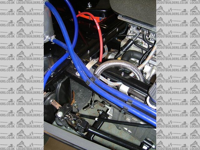
Avoneer - 6/10/05 at 09:30 PM
And the last pic:
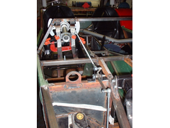
Rescued attachment Top Arm3.JPG
ChrisGamlin - 6/10/05 at 09:41 PM
Hi Pat
If its all pictured in my head properly, Id say you have two options, either to lengthen the gearbox selector arm and shorten the horizontal part of
the rocker arm, that way you retain the movement whilst gaining mechanical advantage by changing the ratio between the length og the selector arm and
the length of the rocker arm
Alternatively, you could extend the vertical part of your rocker arm and shorten the distance between the pivot point and the rod connection point on
the paddles, if this is adjustable?
Chris
Avoneer - 6/10/05 at 09:59 PM
Hi Chris,
Yep - it's really hard to visualise and work out - even with the thing in front of you.
I might wait until the steering wheel is on and then see what it's like.
It's working out a lot simpler than originally intended as well!
Pat...
OX - 6/10/05 at 11:16 PM
i think the problem is the rocker arm,,the vertical part isnt going straight up,its allready over centre .you could try just shortening the the bar
down to the gear change lever and lengthening the bar from paddle to rocker arm,,,but i would look for another rocker arm
chrisf - 6/10/05 at 11:20 PM
Or you could just drill a few holes on the longer arm. Attach the rod end closer and closer to the pivot until it feels better. Your throw will
lengthen but it will be easier to shift. When you find the ideal ratio, you can fabricate a new rocker--or not (I wouildn't).
--Chris
OX - 6/10/05 at 11:27 PM
yes but the rocker arm would give a better feel if it was shaped like an L rather than _/ lmao,,wish i could explain better
Avoneer - 6/10/05 at 11:47 PM
Hi Ox.
Now I can visualise better having all the parts, I'll have a play with a flat rectangle plate and drill loads of holes in it in different places
instead of the top rocker arm, until I come up with the perfect solution.
I'll try the "L" configuration next.
Cheers,
Pat...
Rorty - 7/10/05 at 05:29 AM
Pat, that upper lever is all wrong; wrong angle, wrong lengths.
If you think of the series of levers and paddle like this: If the levers are all the same length as the paddle (and there is zero stiction in the
lever bushes), then the effort to change gear with the paddle would be the same as if you grabbed the bike's shifter the same distance from the
shaft as your finger tips are from the paddle pivot. What's more, the tip of the paddle would move the same amount as the point on the
bike's shifter where you pushed on it.
If you made the levers all longer than the effective paddle leverage, then the effort to change with the paddle would be increased, but the tip of the
paddle wouldn't move very far.
If you made all the levers shorter than the paddle, then you would have a lighter feel to the paddle, but the tip of it would move further.
You can mix and match lever lengths, but if you want to retain a certain ratio, then you'd need to match the inputs and outputs between the
levers.
A good way to assess the required length and weight of pull on the paddle is to pull the bike's shifter at different distances from the shaft
using just your finger tips. Bear in mind that friction or stiction within the lever bushes will also add a degree of stifness.
If you're having difficulties getting your head around the set-up, I'd make the levers up roughly first from flat bar and just pivot them on
plain bolts to start with.
Drill plenty of holes in the levers for quick adjustability and try to match their lengths for consistency.
When you're happy with the feel of it all, then make it up properly and use Teflon impregnated acetal for the bushes.
Avoneer - 7/10/05 at 11:12 AM
Hi Rorty,
I've been waiting patiently for you input.
Thanks, I can visualise it much better now.
Will go the "holey metal bar" route this weekend and work out how much the bike lever needs to move up and down and how much the paddle
moves and post my findings after the weekend for evaluation.
Cheers,
Pat...
Avoneer - 7/10/05 at 11:14 AM
Am I best with a straight "L" shape then?
Pat...
chrisf - 7/10/05 at 11:33 AM
Yeah, or more. I think falling rate lever system would be easiest to shift. So at full press, the angle of the rocker will be more than 90 degress.
I'd shoot for somewhere in the 60 -75 degree range. If you do it like this, the effort to shift will actually degrease as the rocker moves
through its arc.
I did the opposite on my traditional shifter and have a rising rate. Then again, my arm stregth is much more than my finger strength.
--HTH, Chris
Rorty - 7/10/05 at 02:34 PM
I agree falling rate is desirable, but is only possible when using two separate rods for up and down changes. With separate rods, you would obviously
set the "input" side of the levers so they are at right angles to the rods at full throw.
When a single rod is used for both up and down changes, then the "input" side of the levers (everything being equal) should be positioned at
the mid point of the throw, which, unfortunately, constitutes rising rate.
There's a further point to consider: As the actuating rod is attached to one side of your paddle, one side already has a greater advantage than
the other. This means you could actually set the "input" side of the levers off centre (of the throw) to gain a falling rate for the side of
the paddle with the least advantage.
It's virtually impossible to estimate the angles, but they're achievable on paper or CAD.
As suggested before, drill plenty of holes, and as close to each other as is feasible, to make the mock up as adjustable as possible.
Rather than butchering numerous threaded rods while experimenting, you can simply set two rods alongside each other and join them together temporarily
with pairs of hose clips. When the levers and positions are all settled on, you can then cut and thread the rods to the correct length.
I commend using the proper linkage type ball joints and not clevises as the BJs are designed to reduce friction and sloppiness.
If you get the paddle action light and smooth, you'll be delighted, but if it is stiff and requires too much effort, you'll have sore
fingers/wrists and be pretty pissed off.
Sorry, that reads like a dreadful sermon, but I hope it's of some use.
Coose - 7/10/05 at 02:45 PM
Mine worked first time!
I used an equal length 90deg bell-crank, and mounted my push-me-pull-you rod about 120mm from the paddle centre pivot. I can't fault it!

[Edited on 7/10/05 by Coose]
[Edited on 7/10/05 by Coose]
Avoneer - 7/10/05 at 03:36 PM
Hi,
Cheers guys - will take all that onboard this weekend.
Coose - how much movement front to back have you got on your paddles?
Cheers,
Pat...
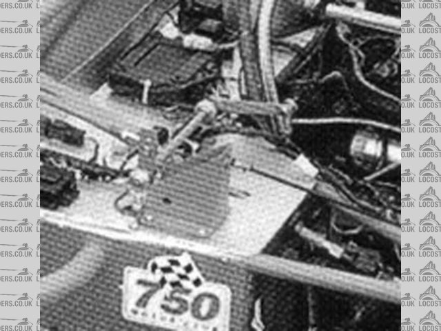
Avoneer - 7/10/05 at 07:19 PM
Just noticed that Stuart Taylor have more of a "tick" bell crank than an "L" - even though the two arms of the bell crank are
spread out.
Shall I have a go like this?
Pat...
Rescued attachment 1.jpg
Avoneer - 7/10/05 at 07:22 PM
And another pic:

Rescued attachment 11.jpg
Mad Dave - 7/10/05 at 08:36 PM
Why not used a cable, its a simple solution?
Description
Description
OX - 7/10/05 at 09:23 PM
quote:
Originally posted by Avoneer
And another pic:
yes,,it is more of a tick shape ,,but the shape doesnt realy matter its the angles at which they are being pushed and pulled from that makes the
difference.
the bar going to the top of the rocker arm is around 90ish degrees and the bar going from the rocker arm to engine is around the 90 mark,,,,the top
arm on your rocker arm is leaning so far back that when you are pulling back on it becouse its allready so far back over centre the only way to make
it change any better would be to pull the top rocker lever down
Avoneer - 7/10/05 at 09:36 PM
I tried with this piece of wood.
The only places I could get a proper full shift were with thejoints on A and B.
The paddles have very minimal movement and have to move the lower gear selector arm a long way.
I guess I am showing my non-engineering background here!
Pat 
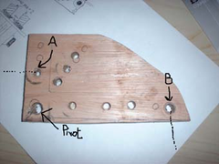

Rescued attachment 1.jpg
Avoneer - 7/10/05 at 09:51 PM
quote:
Originally posted by Mad Dave
Why not used a cable, its a simple solution?
Description
Hi Dave,
Easy solution, but it wouldn't give me the option to increase the ratio of paddle movement to gear lever which needs increasing.
Pat...
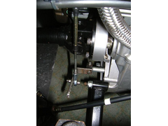
Rorty - 7/10/05 at 10:49 PM
Mad Dave, what prevents your shift lever extension from rotating when you pull on the cable?
Rescued attachment Cable_end.jpg
Avoneer - 7/10/05 at 10:50 PM
If this will assist anyone,
The paddle shift has 1/2" movement from middle to fully forward and 1/2" middle to fully backward.
The end of my gear lever selector moves 1" up and 1" down.
Does that help?
Pat...
P.S. I understand how wrong my linkge is now as the short arm reaches a point where it can no longer rotate and it is just being pulled towards the
steering wheel - thanks OX.
Rorty - 7/10/05 at 11:01 PM
quote:
Originally posted by Avoneer
I tried with this piece of wood.
The only places I could get a proper full shift were with thejoints on A and B.
The paddles have very minimal movement and have to move the lower gear selector arm a long way.
I guess I am showing my non-engineering background here!
Pat
Pat, re-read my earlier post about lever lengths and ratios. You're basically copying the ratio of that existing upper lever which is all
wrong.
I would start with a clean sheet of paper, so to speak, and begin down at the bike's shift lever. Use a Jubilee clip to attach (and alter if
necessary) a link onto the shiftersay, about 60mm from the shaft. Then work back towards the paddle keeping all the levers the same length.
Finally, make the very last L long in the vertical plane and drill lots of holes in it. you can then attach the paddle actuator rod to the various
holes to gain the desired feel.
Once that's done, even the lever lengths out for the final set-up.
As a last resort, you could weld a nut to the pivot of the last lever and screw a bolt into it (with the little BJ stud welded to its top). That way
you can make fine adjustments to the ratio after it's all installed to compensate for stiction/aging etc. Just lock the bolt in place with a jam
nut to prevent it wobbling about.
Avoneer - 7/10/05 at 11:08 PM
Sorry Rorty, struggling with this one.
So I leave the arm that is splined onto the gear box alone and the the rose joint on the end of it and just concentrate on the "L" shaped
rocker and moving the rod that comes vertically up from the end of the gear box selector arm?
Pat...
Avoneer - 7/10/05 at 11:10 PM
Or, move the rose joint on the end of the shifter towards the centre spindle?
Pat...
OX - 7/10/05 at 11:11 PM
quote:
Originally posted by Avoneer
as the short arm reaches a point where it can no longer rotate and it is just being pulled towards the steering wheel - thanks OX.
hehe np..if only i'd explained in a way like you just have
[Edited on 7/10/05 by OX]
Rorty - 7/10/05 at 11:15 PM
Pat, what distance is the gap between the front of the paddle (where your fingers connect with it) to the front of the steering wheel (where your
fingers normally rest)?
Avoneer - 7/10/05 at 11:24 PM
Not got the wheel on yet as waiting to weld on my posh boss (that'll be another long post no doubt).
But, the paddle is adjustable by about 3" up and down the top of the shaft, making the paddle to bell crank actuator arm very adjustable.
Does that help?
Pat...
Rorty - 7/10/05 at 11:26 PM
quote:
Originally posted by Avoneer
Sorry Rorty, struggling with this one.
So I leave the arm that is splined onto the gear box alone and the the rose joint on the end of it and just concentrate on the "L" shaped
rocker and moving the rod that comes vertically up from the end of the gear box selector arm?
Pat...
Forget all the existing lever lengths and start afresh. If the shifter lever on your engine's selector shaft is alloy, remove it and fit a steel
one. That way you can tack a length of "holey flat bar" to it until you resolve the set-up. You can always weld a neater looking lever onto
the splined boss later and either paint it or plate it.
Start with a rod connected about 50mm-60mm from the selector shaft and try to keep the next lever symetrical but make both arms of the upper lever
longer and from "holey flat bar".
If you find the paddle has too great an advantage over the upper lever, adjust (make longer) the effective length of the horizontal arm of the upper
lever.
Rorty - 7/10/05 at 11:34 PM
quote:
Originally posted by Avoneer
Not got the wheel on yet as waiting to weld on my posh boss (that'll be another long post no doubt).
But, the paddle is adjustable by about 3" up and down the top of the shaft, making the paddle to bell crank actuator arm very adjustable.
Does that help?
Pat...
That's sensible. You just don't want a situation where the paddle moves so far that your fingers are struggling to operate the paddle. The
paddle should only just move enough to snick the gears into place.
If you get the set-up wrong, it can be very tiresome to drive.
Avoneer - 7/10/05 at 11:37 PM
Right,
So I need to:
1) Holey flat bar coming from the spline of the gearbox.
2) Rodded rose joint from one of these holes vertically up to the horizontal holey bar of the rocker arm.
3) Vertical holey bar of the rocker arm (assuming we are going for an "L" shaped rocker arm) connected to the paddles via another rose
jointed rod.
4) Both rose joints on both arms of the rocker arm equal distance from the pivot point of the rocker arm - to start with.
5) Start by moving rose joint on the holey bar on the gear selector arm? OR the rose joint on the horizontal holey bar from the rocker arm outward?
6) Sorry for being so thick and thanks for you patience.
Pat...
OX - 7/10/05 at 11:38 PM
yip.it also reduces the chances of getting a false neutral
Avoneer - 7/10/05 at 11:41 PM
What does - being so thick 
Got an Ackerman gear display thing for that!
Pat...
OX - 7/10/05 at 11:45 PM
lol that wont stop anything ,it just reminds you what gear your in
Rorty - 7/10/05 at 11:56 PM
quote:
Originally posted by Avoneer
Right,
So I need to:
1) Holey flat bar coming from the spline of the gearbox.
2) Rodded rose joint from one of these holes vertically up to the horizontal holey bar of the rocker arm.
3) Vertical holey bar of the rocker arm (assuming we are going for an "L" shaped rocker arm) connected to the paddles via another rose
jointed rod.
4) Both rose joints on both arms of the rocker arm equal distance from the pivot point of the rocker arm - to start with.
5) Start by moving rose joint on the holey bar on the gear selector arm? OR the rose joint on the horizontal holey bar from the rocker arm outward?
6) Sorry for being so thick and thanks for you patience.
Pat...
Yes
Yes
Yes
Yes
I would try what that feels like with all connections equal (50mm -60mm from the pivots) and if the paddle is too stiff, raise the BJ on the vertical
arm of the lever.
If the paddle feels too wishy-washy or moves too far, then move the vertical rod outwards along the horizontal arm of the upper lever and try it again
for feel.
You'll obviously need to fit the steering wheel, column and paddle to do all this. Make sure you are seated in the correct position too to try
and replicate, as closely as possible, your actual driving position.
I just tidied this up a bit.
[Edited on 8/10/05 by Rorty]
Avoneer - 8/10/05 at 12:07 AM
Thanks.
Will see what happens over the weekend and report back.
Pat
Mad Dave - 8/10/05 at 06:33 AM
quote:
Mad Dave, what prevents your shift lever extension from rotating when you pull on the cable?
I found the lever arm at a breakers as it is. I assumed the bike it came from had knackered splines on the gear shaft so an m5 bolt was used to stop
it rotating on the shaft. The extension arm is welded on and I only retained the bolt because I could.
Dave


