RazMan
|
| posted on 10/10/10 at 01:30 PM |

|
|
Little 3D design - arrgh!
I am trying to get my head round a 3D model and I am going to admit defeat. Can anyone do a quick 3D model (DXF probably) so that I can get my inlet
manifold machined?
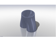
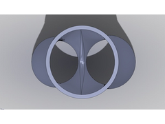
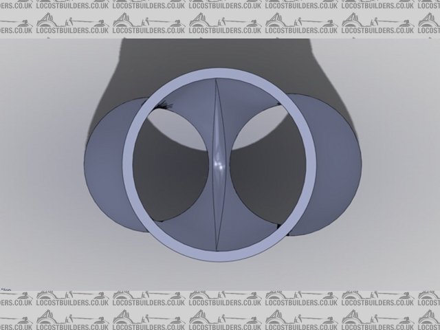
Basically I need a blend between a 50mm round inlet to twin 35+33mm outlets, over a distance of about 70mm.
I have Corel Draw so can export in whatever you need to get started. Any help would be appreciated - it seems I am only ok with 2 dimensions 
Cheers,
Raz
When thinking outside the box doesn't work any more, it's time to build a new box
|
|
|
|
|
zilspeed
|
| posted on 10/10/10 at 01:41 PM |
|
|
How far apart are the centres of the 33mm & 35mm ports ?
My weapon of choice is Autocad with Xtube.
Maybe one of the solidworks experts could also help out with this.
[Edited on 10/10/10 by zilspeed]
|
|
|
RazMan
|
| posted on 10/10/10 at 02:14 PM |
|
|
Here's a pic of the 2D file
 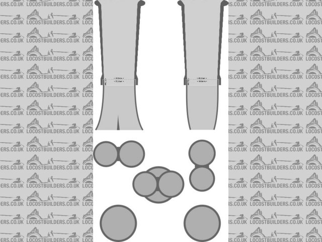
LIM & Trumpet
Looks like some of the dimensions didn't make it - I already have the trumpets so the blend is the only thing left to do. I can then duplicate it
and paste it onto my baseplate ..... all in theory of course 
[Edited on 10-10-10 by RazMan]
Cheers,
Raz
When thinking outside the box doesn't work any more, it's time to build a new box
|
|
|
RazMan
|
| posted on 10/10/10 at 02:40 PM |
|
|
Here's another pic if its any help
[img][/img]
Cheers,
Raz
When thinking outside the box doesn't work any more, it's time to build a new box
|
|
|
brianthemagical
|
| posted on 10/10/10 at 02:43 PM |
|
|
What software are you using?
I've drawn something, not sure if it's what you're after.
If you PM me email address i'll send some pics and a quick description.
|
|
|
zilspeed
|
| posted on 10/10/10 at 02:55 PM |
|
|
Deleted mine because it was rubbish compared to the one below.
[Edited on 10/10/10 by zilspeed]
|
|
|
brianthemagical
|
| posted on 10/10/10 at 03:07 PM |
|
|
 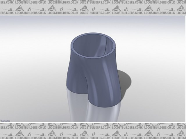
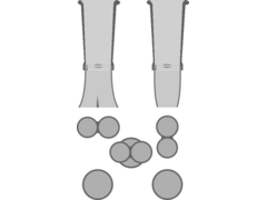
Description
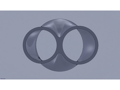 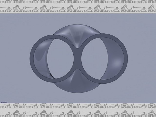
inlet thingy bottom
inlet thingy top
|
|
|
zilspeed
|
| posted on 10/10/10 at 03:17 PM |
|
|
That's much more like it.
Well done sir.

|
|
|
RazMan
|
| posted on 10/10/10 at 03:21 PM |
|
|
Bloomin' heck! I've been messing about for hours and you come up with EXACTLY what I am after in a few minutes! 
U2U coming your way 
Cheers,
Raz
When thinking outside the box doesn't work any more, it's time to build a new box
|
|
|
brianthemagical
|
| posted on 10/10/10 at 03:57 PM |
|
|
LOL
It's only easy if you know how.
Simply, loft the out side, then two lofted cuts for the runners.
Play around with the constraints and such until it is's right.
The wall is 3mm at entry and exit.
Are you after some sort of flange to join to the head?
I'd prefere not to give you a model that you use, as if it's not right you won't be happy, and i'm guessing it's not
cheap tp get one made. Also, my skills fall a little short in terms of CIM.
I'm more than happy to give you/anyone the model, and i don't mind if you do use it, as long as you understand it took about 5 mins with
very little consideration.
I'll give it another look, might be able to do a little CFD if i get chance (probs not today as i've got something important on Monday)
although there's very little such a simple design could be improved.
|
|
|
Confused but excited.
|
| posted on 10/10/10 at 04:22 PM |
|
|
Holy crap!
You can see why he's called 'brianthemagical'.
'cos he knows everything and can do magic as well.
Tell them about the bent treacle edges!
|
|
|
zilspeed
|
| posted on 10/10/10 at 05:00 PM |
|
|
quote:
Originally posted by Confused but excited.
Holy crap!
You can see why he's called 'brianthemagical'.
'cos he knows everything and can do magic as well.
And he's called Brian...
|
|
|
RazMan
|
| posted on 10/10/10 at 06:57 PM |
|
|
quote:
Originally posted by brianthemagical
LOL
It's only easy if you know how.
Simply, loft the out side, then two lofted cuts for the runners.
Play around with the constraints and such until it is's right.
The wall is 3mm at entry and exit.
Are you after some sort of flange to join to the head?
I'd prefere not to give you a model that you use, as if it's not right you won't be happy, and i'm guessing it's not cheap tp
get one made. Also, my skills fall a little short in terms of CIM.
I'm more than happy to give you/anyone the model, and i don't mind if you do use it, as long as you understand it took about 5 mins with
very little consideration.
I'll give it another look, might be able to do a little CFD if i get chance (probs not today as i've got something important on Monday)
although there's very little such a simple design could be improved.
Erm.... you lost me when you said 'loft' Brian, that is soooo close to what I have been trying to do all afternoon. I would be
really chuffed if you can do anything in this area - my 2D skills are ok but I'm a real numpty when it comes to 3D. I will send you my baseplate
drawing and if you could somehow (magically?) put the two together I will be forever in your debt.
My local CNC guy said that he is really tied up for 4 weeks and if I could give him a file to work from it might put me a little further up the
waiting list.
Here is a pic of the baseplate (I will email any files as required of course.
Image deleted by owner
[Edited on 10-10-10 by RazMan]
Cheers,
Raz
When thinking outside the box doesn't work any more, it's time to build a new box
|
|
|
RazMan
|
| posted on 11/10/10 at 07:44 AM |
|
|
I am not sure what thickness the baseplate needs to be - 6mm? 10mm maybe?
Cheers,
Raz
When thinking outside the box doesn't work any more, it's time to build a new box
|
|
|