turbo time
|
| posted on 28/12/04 at 02:54 AM |

|
|
Extend rack, or bump steer?
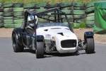
Well, rather than explain entirely in words, I'll just post photos. Obviously, I want as little bump steer as possible, but you'll see
that my steering rack is narrower than my lower control arm mounting points, and even the frame itself. It would be a bit difficult to widen this rack
(Sure, I could do it if need be though). If you can't read the ruler in the photos, the rack is about 19.5" wide, and the frame is
26" wide. For you guys who have already been through the horror of this process, should I even sit down and try to figure out all of the
intersection points for the tie rods with the rack as-is, or just give up and extend it to begin with?
Here are the photos:
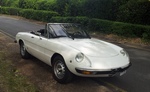
Front end (don't mind the fact that it don't look right, or that it isn't actually attatched to the car yet  : :

Rack I will be using:

Rack with frame:

|
|
|
|
|
Rorty
|
| posted on 28/12/04 at 03:38 AM |
|
|
A racks that is pretty close to being the correct length can often be made to work properly by actually moving it to a "wrong" location.
That is, moving it away from where a rack of the correct length would be mounted.
There are several programs and spreadsheets that can approximate the correct position, but nothing beats using a long pointer or laser pointer and a
projection board.
I'm afraid your rack doesn't come close enough to be "wrongly" placed and still work. What is your rack from?
I haven't built a Locost, but looking at the width of the Escort and Cortina racks, neither of them look as if they are the correct length for a
standard or +4 chassis either, without modification.
I haven't seen any posts about shortening racks (that I can recall), so I presume most people just attach the tie rod extensions and make the
best of it.
Anyone actually measured their bump steer on a Book or +4 chassis with either steering racks?
Cheers, Rorty.
"Faster than a speeding Pullet".
PLEASE DON'T U2U ME IF YOU WANT A QUICK RESPONSE. TRY EMAILING ME INSTEAD!
|
|
|
zetec
|
| posted on 28/12/04 at 08:58 AM |
|
|
I'm no expert (should read knows bugger all) but I can't see the swivel joints for the track rods...Would it be possible to move those
further out rather than chop the rack about?
|
|
|
sgraber
|
| posted on 28/12/04 at 10:15 PM |
|
|
Oh, that rack won't do. not at all. You could modify it one of several ways.
Take it apart and weld extensions onto each end.
fabricate a long, strong bar that straps across the outside of the rack. It attaches solidly only to the two outer pivot points and does not touch the
rack housing. This bar extends the outward location of the rack joints... It would require some fabrication, but would avoid the need to source a new
rack and would allow you to create a rack of exactly the length you wanted. Need me to draw a picture?
Option 3-
Sell it and buy something more suitable.

Graber
PS- when I designed my front suspension, the rack length was a critical measurement. Is your suspension geometry based on an existing design?
[Edited on 12/28/04 by sgraber]
Steve Graber
http://www.grabercars.com/
"Quickness through lightness"
|
|
|
sgraber
|
| posted on 28/12/04 at 10:40 PM |
|
|
This is my idea to lengthen the rack without taking it apart.
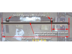 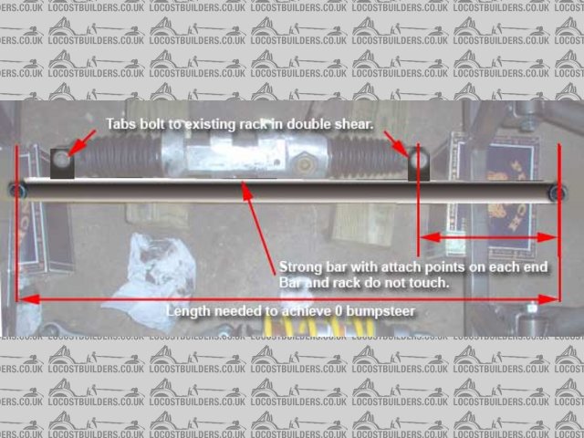
Rack Extender Idea
Steve Graber
http://www.grabercars.com/
"Quickness through lightness"
|
|
|
turbo time
|
| posted on 29/12/04 at 04:21 AM |
|
|
Hey, I appreciate the replies.
This rack happens to be out of nothing.... as far as I know. It's an "Appleton" racing rack that I got for $20 at a nascar/dirt
track flea market (apparently it goes for $400 new). And this leads into Steve's question, I had a rack that went with my suspension design
(although it's not based verbatim on any particular OEM car, just on info from this forum, books, software, etc..), it was the right length, but
was heavy, 4 turns lock-lock, and about $80. This one is under 10 lbs, is 1.5 turns lock-lock, and was cheap, so you can understand why I'm keen
on using it. I may have mentioned before that this build is primarily for the Locost class Grassroots Motorsports $2005 (or $2006) event, so cheap
sometimes dominates common sense (wait til you see my bodywork!! ). The only drawback would be that this rack requires heim joints as the inner
tie-rod ends. Fortunately I got about 3 dozen of them at the flea market as well, including a little bucket of 15+ 1/2" ones for $3.00, plenty
to do my rear suspension and then some. Ok, I'll stop being a douchebag now, my mom just taught me bargain shopping to a fault .
That's a fabulous drawing steve (and how do you whip them up so quickly? that would take me all day LOL ), I was about ready to weld extensions
to the rack, but that seems like a very good alternative. You mention using bar though (I interpret as being solid, as opposed to hollow
"tubing" ), would it really need to be bar? Are the forces that tremendous? I was hoping maybe 14 or 12 Ga 1" tubing would do the
job.
Also, for Steve, or anyone else who has done this process of putting the tie rod in the zero-bump position, was there a favorite resource for the
information/procedure? I have come across a few DIY descriptions on how to find the correct place, and am downright confused by some, am unsure about
others that don't seem to be consistent with the previous info I had read in every respect, and have found others that spelled it out so plainly
that it seemed too damn easy . Let me know what resource you liked, and the physical method that worked best (strings, laser pointer, laser level,
etc..)
Thanks,
Kent
[Edited on 29/12/04 by turbo time]
|
|
|
Rorty
|
| posted on 29/12/04 at 05:22 AM |
|
|
For Graber's adaptation, I would use a length of tube with a clevis welded into each end.
I don't know of a URL for "lasering" bump steer, but it's a fairly basic process. You may not be able to completely eliminate
bump steer, but you want to at least minimise it and (on a road car) tuck any residual bump steer away into full droop.
You can buy bump steer gauges from race shops (I think they're made by Longacre) which utilise dial indicators. You should be able to find
something about them on the web.
This is the one man laser method that I use: Assuming the tie rods are attached to the car and the rack is temporarily clamped in place, remove the
front shocks and jack the car up by an amount equal to full droop. (The wheels should be touching the floor). Set the toe and centre the steering.
I normally use a cheap laser pointer that I tape or Blu-Tac mid-way up onto one of the front wheels. You'll need to put a brick on the brake
pedal to stop the wheel rotating.
Turn the laser on so it's dot shines on a white wall or board about 3-4 metres in front of the car. With a marker pen, accurately place a mark
on the laser dot on the board, with a leader and number.
Gently lower the jack by about 25mm and again, mark the laser dot, and again, number it. Repeat until the car has dropped to the equivalent of full
bump. Make a special note of the position of the dot at (loaded) ride height.
If the pen marks on the board appear either side of the ride height dot, you've got bump steer. Try moving the rack by spacing it with shims of
sheet metal, washers etc. both backwards, forwards, up and down and repeat the laser process until the dots are as close together as possible or at
least until the full droop dot is just outboard of ride height.
Moving the rack up in the chassis increases toe-out in bump, and toe-in in droop. Moving the steering down, toe-out increases in droop, and toe-in
increases in bump.
Moving the steering to the rear, toe-in increases in bump and droop. Last but not least, if you move the rack foreword toe-out increases in both bump
and droop.
You can also do it by raising the wheel and leaving the car stationary on axle stands. You'll either need incremental objects on which to rest
the wheel or else an assistant to mark the board. The dots will (most likely) show up as a convex or concave line using this method, but the same
principles apply. The aim is to get the line as straight as possible or at least to just turn out at the bottom (full droop).
I'm sure others here have their own version of this job, but I hope you get the idea.
Cheers, Rorty.
"Faster than a speeding Pullet".
PLEASE DON'T U2U ME IF YOU WANT A QUICK RESPONSE. TRY EMAILING ME INSTEAD!
|
|
|
kb58
|
| posted on 29/12/04 at 06:18 AM |
|
|
And getting bump steer minimized takes hours, so don't be disappointed, wondering where all the time went for such a silly little task...
Mid-engine Locost - http://www.midlana.com
And the book - http://www.lulu.com/shop/kurt-bilinski/midlana/paperback/product-21330662.html
Kimini - a tube-frame, carbon shell, Honda Prelude VTEC mid-engine Mini: http://www.kimini.com
And its book -
http://www.lulu.com/shop/kurt-bilinski/kimini-how-to-design-and-build-a-mid-engine-sports-car-from-scratch/paperback/product-4858803.html
|
|
|
sgraber
|
| posted on 29/12/04 at 07:21 AM |
|
|
Tube is fine. I would use .120 wall DOM. The clevis Idea is good, but with the .120 wall you can tap threads into it and use 1/2" rod ends...
These can then fine tune the rack even more.
Since your front suspension is not attached to a car at this point, you can also set it up on a sturdy and flat surface like a table.
I did something similar to what Rorty suggested, but instead of pointing at a wall, I had the chassis up on a table, the a-arms and uprights on, no
shocks, the tie rods in place and the rack loosely fitted to the frame in-situ but with clamps to fix it firmly. I had a laser level that draws a line
attached to the hub face aimed it at the floor. At ride height the laser level was parallel to the axis of the car. At 1" bump and droop
increments I would measure the difference of the laser to the original line. By adjusting the rack up or down (even by millimeters) you can dial out
the bumpsteer. Mine has less than 1mm of steer through 12cm of travel by using this method. If your chassis is already built, then Rortys method would
be better. But since you have only the front cradle it may be difficult to jack it up and down without shifting it and inducing errors.
You should also take note of the placement of the rack in the fore-aft position. It should be set so that as the car is steering straight ahead, the
rack and the tie-rods form a straight line across the car. If you move the rack too far forward or too far back you change the rate of ackerman as the
tie rods change their arc of rotation relative to each other. Not that ackerman really matters to us home-builders, but just FYI.
And what Kurt said. Yeah. and you should have a helper.
Steve Graber
http://www.grabercars.com/
"Quickness through lightness"
|
|
|
Ratman
|
| posted on 30/12/04 at 01:27 AM |
|
|
I've done smilar things to what Steve describes above and agree 100%. Remember that you are looking for tie rods that are a similar length to
your A arms, not a total rack length equal to your chassis width. Because of the Akerman geometry, this ususally means that you rack length is less
than the chassis width (for a rack behind the axle). For a low tech indicator, rather than the lazer pointer, I have clamped one end of a 3m length of
tube to the hub, and hung the other end from the roof with a long piece of string. This tube becomes your pointer, and the idea is to adjust the rack
location untill the end of the pointer doesn't move while you lift the suspension through it's full range of movement. You can do all this
with the rack that you already have, but you will only be able to locate one end of it correctly after experimenting with different lengths of tie
rod. With this knowledge, you can then adgust the ength of the rack (or find a longer one) to achieve identical geometry at the other side. For these
trials, you can make a tempory tie rod out of anything handy. I like to use bamboo and hose clips, or bits of split Al tube. I will come back and
edit this post with some pix of doing this all on a friend's Fiat "500", converting it to rack&pinion. I would caution against
any welding to extend the rack length. This can be very risky. If you decide on a small extension, say less than 100mm, then it is common to make
threaded extensions that screw into the end of the rack and have some way of locking them in place. As a last note.. If your hubs were originally for
a car with a steering box, then you might wind up with negative akerman.. but this won't matter much. And as a second final note (sorry to be
going on a bit) if you are searching for a replacement rack, don't take much notice of the "turns, lock to lock" values. What you
want is a rack that will move at least 60mm for one rotation. These are not easy to find. If you have less than 50mm, depending obviously on the
steering arm length, but for typical normal car units there is a fair chance your steering will come out very low geared.. which is a pain. Sorry to
be so verbose.. I'm stuck inside with a cold, and nothing else to do. Cheers, Brian

[Edited on 30/12/04 by Ratman]
|
|
|
turbo time
|
| posted on 3/1/05 at 06:28 AM |
|
|
Ok, I have got it, hopefully I can get set up tomorrow, I should be able to take the whole front end away and clamp it down to the table in the
workshop where it'll be easier to work with in getting minimal bump steer.
I still can't get over what a great forum this is with great members, Thanks for all of the info provided!
-Kent
|
|
|
pk
|
| posted on 4/1/05 at 01:50 PM |
|
|
Bump steer - Been there done that and sorted it!
I built my car to the book using an Escort rack and suffered bad BS. The trouble was that I also found that it was really easy to get used to, after
a while it seems to go away. That is until you find a new bumpy road! The other problem is that in a turn it can be helpful to have some BS or
thats what Im lead to believe. I agree with Rorty you can remove most of it by moving the rack around as I have proved to myself. I got the BS
down to less than 1.5mm. But I found that shortening the rack by 100mm and lengthening the track rods by 50 mm each removed it all. There were some
down sides though as the column has to be positioned nearer the centre line and in my case I had to put another two UJs in the system. However I
found the task very interesting and I learnt a lot about the complexity of the system as a whole. It does take a long time though as every time an
adjustment is made to the position of the rack the length of the track rods has to also change to ensure that the toe remains static. Id say its
worth the effort of at least finding out what BS you have and how moving the rack affects the amount of BS.
|
|
|
phelpsa
|
| posted on 4/1/05 at 02:02 PM |
|
|
Can you move the escort steering rack backwards in the chassis a bit to get minimum BS?
|
|
|
pk
|
| posted on 5/1/05 at 01:29 PM |
|
|
Bump steer
Yes, moving the rack backwards and down does remove some of the BS but has other effects if i recall correctly. At the end of the day moving the
brackets to a compromise position is harder than shortening the rack and eliminating the BS IMHO.
|
|
|
Rorty
|
| posted on 7/1/05 at 02:50 AM |
|
|
This taper stud can be of use for fine tuning bump steer if it's not possible or convenient to move the rack.
It's really designed to convert from a conventional automotive type rod end to a spherical bearing type.
The relative position of the rod end on the steering arm can be adjusted by winding the jam nuts up or down.
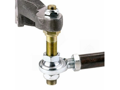 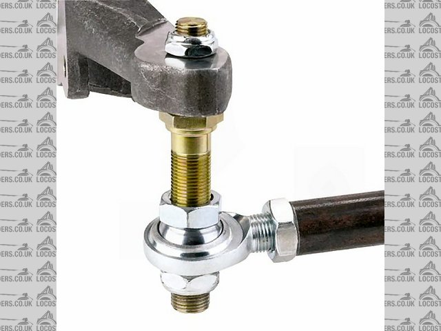
Rescued attachment rod_end_stud_01.jpg
Cheers, Rorty.
"Faster than a speeding Pullet".
PLEASE DON'T U2U ME IF YOU WANT A QUICK RESPONSE. TRY EMAILING ME INSTEAD!
|
|
|
GTAddict
|
 posted on 7/1/05 at 11:19 PM posted on 7/1/05 at 11:19 PM |
|
|
Oooh, ooooh, oooh...
That taper stud is just what I'm looking for for the Libra. Where do I look for one, Rorty?
Mark.
|
|
|
Rorty
|
| posted on 7/1/05 at 11:41 PM |
|
|
quote:
Originally posted by GTAddict
That taper stud is just what I'm looking for for the Libra. Where do I look for one?
The're pretty easy to make yourself if you have, or have access to, a lathe. Use a good alloy steel and prefferably have them heat treated.
The one in the pic above actually comes from the US, from
Speedway Motors
Cheers, Rorty.
"Faster than a speeding Pullet".
PLEASE DON'T U2U ME IF YOU WANT A QUICK RESPONSE. TRY EMAILING ME INSTEAD!
|
|
|
Rorty
|
| posted on 7/1/05 at 11:45 PM |
|
|
If you don't require that amount of adjustability, you could just use an ordinary studded rod end. Aurora supply studs for theirs and their
agents will usually fit them for free when you buy the rod ends.
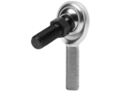 
Rescued attachment studded_rodend.gif
Cheers, Rorty.
"Faster than a speeding Pullet".
PLEASE DON'T U2U ME IF YOU WANT A QUICK RESPONSE. TRY EMAILING ME INSTEAD!
|
|
|