flak monkey
|
| posted on 30/4/07 at 12:51 PM |

|
|
Pictures of pinto engine bays required
Hi gents and ladies,
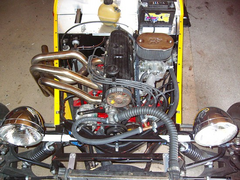
Has anyone got any good pics of SVA passed pinto engine bays?
I am wondering what the hell to do with the pipe that goes from my header tank to the pump and with the breather. Currently they are cable tied
together and attached to the alternator adjuster bar, and to a bracket I made to go on the bell housing. But I think they flop about a bit too much
for Mr SVA mans liking.
That, and it will be interesting to see how others have laid it all out.
Cheers,
David
Sera
http://www.motosera.com
|
|
|
|
|
nick205
|
| posted on 30/4/07 at 02:28 PM |
|
|
Can't find a photo to hand David, but I routed the pipe from my scuttle mounted header tank between the rocker cover and carb. I my case it
then T's into the coolant pipe looped from the pump round the front of the engine to the inlet manifold (if that makes sense).
I made up some small ally brackets with rubber lined P clips which fit under the inlet manifold nuts and support the hose out of harms way. If you
use all 3 manifold studs as fixing points it's quite a neat job.
SVA man was fine with it!
HTH
Nick
[Edited on 30/4/07 by nick205]
|
|
|
flak monkey
|
| posted on 30/4/07 at 02:35 PM |
|
|
Thanks for that Nick, I am using twin DCOEs though, and dont have the luxury of having the nice short pipe runs to the inlet manifold, then to the
pump. Mine is one long pipe from the scuttle mounted tank, to the pump and there is literally nowhere to fix it to.
David
Sera
http://www.motosera.com
|
|
|
nick205
|
| posted on 30/4/07 at 02:39 PM |
|
|
Can you take it down the side of the engine bay (carb side) and loop it around the front of the engine?
A few P clips along the chassis rail would secure it OK.
Edit to say...
Just re-read your 2nd post - mine's very similar being effectively a lon run from the tank to the pump, just with T taken out at the front for
the inlet manifold.
DGV manual choke carb, so no plumbing for the auto choke.
I'll try and find a pic to show what I mean.
[Edited on 30/4/07 by nick205]
|
|
|
nick205
|
| posted on 30/4/07 at 03:04 PM |
|
|
here you go...
Rescued attachment P1020500.JPG
|
|
|
indykid
|
| posted on 30/4/07 at 03:13 PM |
|
|
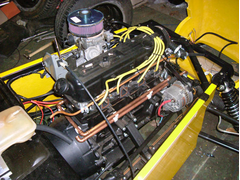
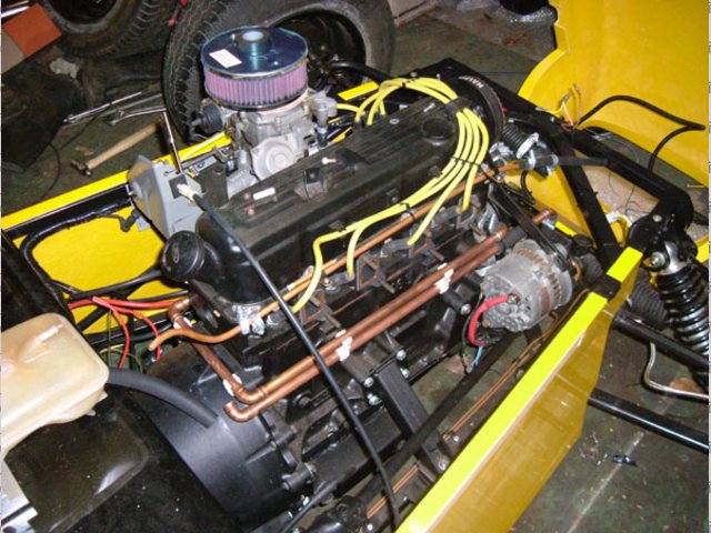
for a cleaner solution, use 15mm copper pipe with solder ring fittings.
mine went, in order from the waterpump:
water pump
a short piece of rubber hose
a 90° solder ring fitting
long piece of 15mm copper down the side of the block
90° solder ring fitting over bellhousing
6" of copper
90° solder ring
rubber hose
header tank
paint it black an most people will be none the wiser. looks a lot neater than swoopy rubber hose imho too.
i'll try find a pic shortly
hth
tom
[Edited on 30/4/07 by indykid]
|
|
|
bob
|
| posted on 30/4/07 at 03:20 PM |
|
|
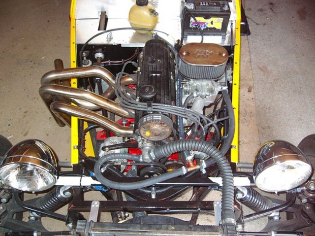
I went up over the cam cover, might be some pics in the archive from the old pinto.
This is the best i can find at the moment.
Rescued attachment 2Dscn0150.jpg
|
|
|
indykid
|
| posted on 30/4/07 at 03:21 PM |
|
|
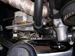
forgot to mention, the 15mm pipe was clipped into a central heating pipe type clip at the back rivetted onto an L bracket onto the bellhousing
bolt.
there are 2 15mm pipes as i ran a rail from the manifold round to the water pump and a seperate run to a t into the bottom hose from the header tank
as the headertank was being filled by the water coming round from the manifold, so pushing all the air back into the system. if you don't have
the manifold pipe, as i won't when i get my bike carbs, it's not a problem.
you can see the breather pipe in that pic too. it eventually got fastened on with p clips on small ally brackets that fastened it onto the rocker
cover bolts.
hth
tom
Rescued attachment water pipes.jpg
|
|
|
flak monkey
|
| posted on 30/4/07 at 06:56 PM |
|
|
Thanks guys, looks good. Not sure about the over the rocker cover solution as the full level of my header tank is only just above the top of the head,
so would get air in the pipe.
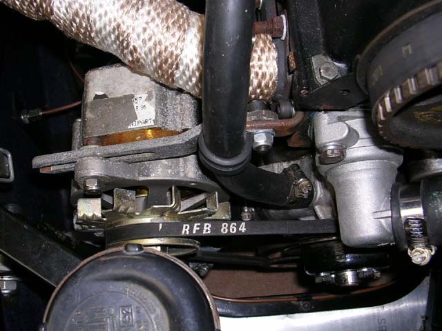
The copper pipe idea looks like a neat idea, and I have loads of plumbing stuff at home  Whats the clip attached to at the front of the engine? Whats the clip attached to at the front of the engine?
David
Sera
http://www.motosera.com
|
|
|
indykid
|
| posted on 1/5/07 at 07:59 PM |
|
|
the top two of the pipes is the one that's supported. the front is straight into the water pump, the back on the bracket on the bellhousing.
the other 2 clips are just back to back, and support the lower pipe off the top one.
if you want any more info, just drop me a u2u
hth
tom
|
|
|