Jesus-Ninja
|
| posted on 19/1/08 at 02:13 AM |

|
|
help with trig and equations!!
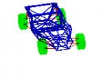
OK, I'm stuck.. see attached pic
Given r, v, h, a, d and u, I want to know phi
so far I have got:
Sin phi = x/u
x + y = sqrt(a^2 + d^2)
x = sqrt(a^2 + d^2) - y
Sin phi = (sqrt(a^2 + d^2) - y) / u
y = z - h
Sin phi = (sqrt(a^2 + d^2) - (z - h)) / u
Sin phi = (sqrt(a^2 + d^2) - z + h) / u
r^2 = t^2 + z^2
z = sqrt(r^2 - t^2)
Sin phi = (sqrt(a^2 + d^2) - (sqrt(r^2 - t^2)) + h) / u
and now I'm stuck. I need to loose t from the equation and get v in there.
grrrrr!!.jpg)
|
|
|
|
|
emsfactory
|
| posted on 19/1/08 at 03:34 AM |
|
|
Is the angle between x and w a right angle?
If so break down U to get x, sin phi is x/u
[Edited on 19/1/08 by emsfactory]
|
|
|
TheGecko
|
| posted on 19/1/08 at 08:46 AM |
|
|
I'll assume that what you're trying to model here is a double wishbone suspension where u is the upright and
r and a are the wishbones. The generalised solution to this problem is found in the subject of kinematics - in this
case, 4-link kinematics (the chassis is considered a fixed link). Here's a brief summary I wrote on the Locost_Theory mailing list way back in
December 1999.
Here's a potted summary (with a very brief introduction to planar kinematics).
<---h--->
A o---------o B
|
a | b
|
O |<-----g-----> C
__o______________o__
////////////////////
The above diagram is a 4-element planar linkage (basically, all of the
hinge axes are parallel). The 4 joints are labeled O, A, B & C. The
lengths of the 4 elements are a, h, b & g (clockwise from the left).
Element OC is considered the "fixed" element for these discussions. In a
suspension design problem this would be the chassis and the diagram would
need to be rotated 90 degrees one way or the other. If you were modeling
the motion of a suspension upright you would represent the upper and lower
wishbones with (say) OA and CB; AB would be the upright and O & C the
chassis mounting points for the wishbones.
Lets call the inside angle between OA and OC the input angle and call it
theta or T (hmmm, email program can't do greek characters - what a surprise
 . The output angle (call it phi or P) is between OC and CB but on the . The output angle (call it phi or P) is between OC and CB but on the
*outside* of the link assembly (ie roughly where the letter 'C' is in the
diagram). .
The formula to solve for P(T) (that's phi as a function of theta) is pretty
simple.
A(T) = 2ab.cos(T) - 2gb
B(T) = 2ab.sin(T)
C(T) = g^2 + b^2 + a^2 - h^2 - 2ag.cos(T)
P(T) = arctan(B/A) + arccos(C/sqrt(A^2 + B^2))
P(T) = arctan(B/A) - arccos(C/sqrt(A^2 + B^2))
Note that there are two solutions as the output link may be able to sit in
two different positions for the same input angle. Also, if
A^2 + B^2 - C^2 < 0
then the linkage can't be assembled in that position.
The diagram is a little scrambled fom cutting and pasting etc but I assume you can work out the principles. If not, search for "Four Link
Kinematics" and you should find plenty of reference material.
Dominic
|
|
|
Jesus-Ninja
|
| posted on 19/1/08 at 10:52 AM |
|
|
quote:
Originally posted by emsfactory
Is the angle between x and w a right angle?
If so break down U to get x, sin phi is x/u
[Edited on 19/1/08 by emsfactory]
erm... isn't that what I wrote?
sorry - see what you mean now. Basically, I want to get phi in terms of r, u, a, d, h and v
[Edited on 19/1/08 by Jesus-Ninja]
|
|
|
Jesus-Ninja
|
| posted on 19/1/08 at 11:30 AM |
|
|
quote:
Originally posted by TheGecko
I'll assume that what you're trying to model here is a double wishbone suspension where u is the upright and
r and a are the wishbones. The generalised solution to this problem is found in the subject of kinematics - in this
case, 4-link kinematics (the chassis is considered a fixed link). Here's a brief summary I wrote on the Locost_Theory mailing list way back in
December 1999.
Here's a potted summary (with a very brief introduction to planar kinematics).
<---h--->
A o---------o B
|
a | b
|
O |<-----g-----> C
__o______________o__
////////////////////
The above diagram is a 4-element planar linkage (basically, all of the
hinge axes are parallel). The 4 joints are labeled O, A, B & C. The
lengths of the 4 elements are a, h, b & g (clockwise from the left).
Element OC is considered the "fixed" element for these discussions. In a
suspension design problem this would be the chassis and the diagram would
need to be rotated 90 degrees one way or the other. If you were modeling
the motion of a suspension upright you would represent the upper and lower
wishbones with (say) OA and CB; AB would be the upright and O & C the
chassis mounting points for the wishbones.
Lets call the inside angle between OA and OC the input angle and call it
theta or T (hmmm, email program can't do greek characters - what a surprise
. The output angle (call it phi or P) is between OC and CB but on the
*outside* of the link assembly (ie roughly where the letter 'C' is in the
diagram). .
The formula to solve for P(T) (that's phi as a function of theta) is pretty
simple.
A(T) = 2ab.cos(T) - 2gb
B(T) = 2ab.sin(T)
C(T) = g^2 + b^2 + a^2 - h^2 - 2ag.cos(T)
P(T) = arctan(B/A) + arccos(C/sqrt(A^2 + B^2))
P(T) = arctan(B/A) - arccos(C/sqrt(A^2 + B^2))
Note that there are two solutions as the output link may be able to sit in
two different positions for the same input angle. Also, if
A^2 + B^2 - C^2 < 0
then the linkage can't be assembled in that position.
The diagram is a little scrambled fom cutting and pasting etc but I assume you can work out the principles. If not, search for "Four Link
Kinematics" and you should find plenty of reference material.
Dominic
Thanks Dominic.
Would you believe that "four link kinematics" returns all of 3 results from Google!
|
|
|
Jesus-Ninja
|
| posted on 19/1/08 at 12:39 PM |
|
|
Could someone check this for me, please.
T = 180 - Q - S
Sin S = d/a
Tan Q = v/h
T = 180 - ATan(v/h) - ASin(d/a)
A(T) = 2cu.Cos(T) - 2au
B(T) = 2cu.Sin(T)
C(T) = a^2 + u^2 + c^2 -r^2 - 2ca.Cos(T)
c = sqrt (v^2 + h^2)
P(T) = ATan(B/A) +or- ACos(C/sqrt(A^2+B^2))
KPI = 180 - P - V
Cos V = d/a
V = ACos (d/s)
KPI = 180 - P - ACos(d/a)
[Edited on 19/1/08 by Jesus-Ninja].jpg)
|
|
|