dblissett
|
| posted on 22/12/03 at 09:07 PM |

|
|
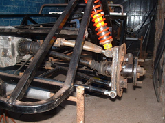
opions on my irs
this is my first attempt at irs
all the three joints on the hub carrier are m14 rod ends
it is a mix of my work and some of the avon dimentions
before i tidy this lot up is it ok
if i have got anything wrong or missing
now is the time to find out not in front of the sva tester
be gental lads
cheers dave
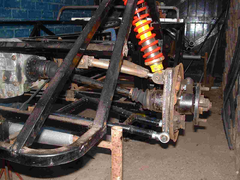 
Rescued attachment backend 031a.jpg
|
|
|
|
|
JoelP
|
| posted on 22/12/03 at 11:53 PM |
|
|
didnt realise irs was that simple! not a clue if its right but looks OK to me!
|
|
|
James
|
| posted on 23/12/03 at 02:02 AM |
|
|
Hey a larger than life picture! 
Glad to see someone else like me foolish enough to do their own IRS system! 
Your design looks pretty to similar to McSorley/MK/Luego so presumably it'll work as long as your dimensions are correct! 
I'm a little concerned about a couple of welds though.
Firstly, I wonder if you didn't have the current quite high enough when you did the uprights. Maybe either upping the power or dropping the wire
speed a little would give a nicer finish.
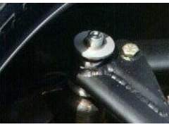
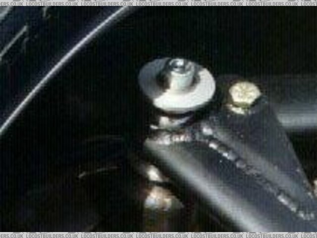
Also, the upper wishbone's bush weld is possibly a little insubstantial. I wonder if you noticed the weld pool 'bubbling' as you got
to the area where that 'hole'/spot is that I've circled. As I wonder if it may be the same as a problem I suffered where
super-heated gas was expanding inside the tube and escaping by 'blowing through' the molten metal?
[img] http://www.locostbuilders.co.uk/photos/showppic.pl?file=daves.jpg&archive=James [/img]
You can cure this by drilling small hole in the tube and welding over this quickly once the whole thing is cooled down.
Anyway, there are far better and more experienced welders that me here who maybe able to give better advice- a u2u to Mark Allanson might be a good
idea if he doesn't spot this thread himself!
Hope that helps and was constructive!
Cheers,
James
[Edited on 23/12/03 by James]
|
|
|
kingr
|
| posted on 23/12/03 at 02:24 AM |
|
|
I was thinking just the same thing as James. It's hard to tell what's down to weld quality and what's down to what appears to be
some pretty heavy JPEGing in the picture - Can I recomend you decrease the resolution and also decrease the compression.
Also, it's hard to see what goes where with only one picture of one side, so it's hard to give comments. Apart from the welding,
everything that I can see looks pretty good.
Kingr
|
|
|
stephen_gusterson
|
| posted on 23/12/03 at 10:12 AM |
|
|
bear in mind that rose joints used with sideways loading are rated at approx 15% of their full load.
Under braking the rose joints will be trying to 'twist' as the braking force goes into the 'bones'. You dont want the bearings
popping out of the shanks.
I have used rose joints - M16 - but my system is completly different.
In any case, the load on the rear will be less than the front - where I have 4 M16 units each side.
Im just a pessimist - if similar systems have similar joints and sizes its likely ok.
bear in mind the rating of joints varies widely - race joints are over 100% higher rated than std industrial ones.
ALSO get rubber covers for the joints - you can buy washers with rubber skirts on them. crap in the joint will make it fail early.
atb
steve
ps
obviously the suspension is in full droop - but it looks like the angle of the shaft to hub CV joint is a bit big. Also, the shaft looks like its
running at an angle at normal ride height. May not be a problem at all, but I set my system up so that shafts were as level as possible.
At full droop, do you still have slack in the shaft (float) side to side. On a bump you will get full droop sometimes.
[Edited on 23/12/03 by stephen_gusterson]
|
|
|
dblissett
|
| posted on 23/12/03 at 07:23 PM |
|
|
thanks for your coments
ref the welds these are only temp as my farther inlaw is a coded welder and will come round to laugh/sort them out
i went for 14mm because i have seen some other irs systems with 1/2" fitted
steven what do you mean float
the whole upright has no play but still moves freely
as for the dimentions i hope that because all three conections are rod ends i should have enough adjustment
can anyone recomend what paint to use on the wishbone i painted the bottom one with hamerite smooth but it chips very easily
cheers dave
|
|
|
stephen_gusterson
|
| posted on 23/12/03 at 11:20 PM |
|
|
float - i meant side to side movement in the drive shaft....
basically, the drive shaft gets longer and shorter as it scribes a radius from the diff to the cv joint at the wheel.
The cv joints take up the need for this change of 'drive shaft radius' by allowing the inner race to 'float' sideways in the
outer cage.
You dont want the shaft pulling the cage too far out at max radius, or 'bottoming' in the cv joint at minium radius.
so, at 'droop' and max compress, you should be able to feel 'slack' in the shaft across the car
did that make sense?
atb
steve
|
|
|
Rorty
|
| posted on 24/12/03 at 04:18 AM |
|
|
Just from looking at the pic, the top bone looks very short in relation to the bottom one. Have you drawn the design out to scale to see how the wheel
behaves in bump and droop? Failing that, remove the shock and cycle the suspension and observe. You don't want any large changes in camber in
droop, and only slight neg camber gain in bump.
Yup, get the outlaw to run some welds over the wishbones. You may need to grind those porous ones out first.
Just a word of caution with using rod ends in single shear like you have. If the joint does decide to pop, there's nothing to prevent it from
pulling the whole way through the rod end. You should fit some fail-safe washers under the heads of any single shear bolts. Don't use just any
old washers either, as a short trip along the road with a disloged rod end can very quickly chew through a plain 1.5mm - 2mm thick mild steel washer.
Their underside should be tapered. If you can't buy any where you are, have some turned up on a lathe. See pic below.
I wouldn't bother fitting those Sealsit seals to your rod ends. They rely on the (weak) pressure of the rubber to form the seal and road dirt has
a habit of getting past better seals than those. Once it's in, it'll grind away at the bearing. If you're using PTFE lined rod ends,
then you'll not need any form of seal or lubricant either.
Rescued attachment fail_safe_washer.jpg
Cheers, Rorty.
"Faster than a speeding Pullet".
PLEASE DON'T U2U ME IF YOU WANT A QUICK RESPONSE. TRY EMAILING ME INSTEAD!
|
|
|
blueshift
|
| posted on 24/12/03 at 11:15 AM |
|
|
Re paint, a lot of people on here rate the POR15 products. we intend to use it.
|
|
|
dblissett
|
| posted on 24/12/03 at 02:29 PM |
|
|
irs
thanks i will use much stronger washers
the brackets are made as per book 1/8 plate
the rod ends are skf with the bronze liners these take more load than the ptfe ones
i think the camber will change as the suspension moves up and down how much is aceptable
i also have a photo from the back of the upright if this will help
thanks dave
thanks dave
|
|
|
dblissett
|
| posted on 24/12/03 at 03:08 PM |
|
|
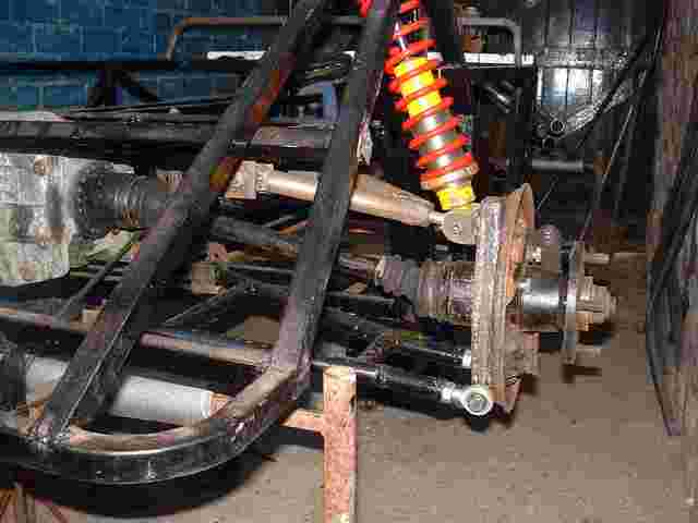
photo
i have learnt how to make the pics smaller
does this help you sus out if the top wish bone is long enough
cheers dave
Rescued attachment backend 0311.jpg
|
|
|
stephen_gusterson
|
| posted on 24/12/03 at 03:20 PM |
|
|
i was told or read somewhere that you may not pass SVA unless you have joint covers - but that may be bo%^ocks. I used em just in case.
If you look on TOL
http://groups.yahoo.com/group/locost
in the files area
there is a DOS program that models suspension movement - will also tell you the drriveshaft length variation too, as well as your wheel angle change
over the suspension travel
atb
steve
ps - a pic wont show if its 'long enuf'. You need to model it on paper or on software, or at least move the wheel thro full bounce with
summat like a spirit level on the wheel mounting face.
I ballsed up my front susp first time by not measuring the front ball joints at their pivots. I measured the upright taper ends. This gave me approx
20mm error in (i think) a 180mm dimension between the uprights. This alone gave a massive positive camber gain on bump - about 2 - 3 degrees I
think.
Had to do it all again and now have less than 0.5 degree negative gain over normal travel.
there is an awful lot to be said to using std book suspension.........
[Edited on 24/12/03 by stephen_gusterson]
|
|
|
dblissett
|
| posted on 30/12/03 at 08:37 PM |
|
|
thanks
thanks for your help steven i have checked to see if the camber changes as the suspension moves up and down it seems to be allmost nothing
so i am quiting while i am ahead
as for the drive shaft it seems to sprug loaded and there is still 19mm of movement towards the upright but none back into the diff
its as if the springs are under slight compresion
this is constant throught the full suspension range of movement
it all seems right should i start on the front end now?
cheers dave
|
|
|