
Speeduino
Rudy - 3/9/23 at 01:23 PM
Hi,
are someone running on speeduino ?
I was thinking to put a speeduino system on my Tiger zetec silverhead, now I am running with original ford mondeo ecu and would like to try to play
with the management of the engine.
I am at the beginning of the project so any advice is appreciate.
Sorry about my English
Rudy
scudderfish - 3/9/23 at 02:56 PM
I use it to run my V8. It works really well, much better than the MS1 it replaced. Just make sure you read all the docs. I found it a good help to
install it on an Arduino, add a simulator board and fiddle with it on the desk.
Sanzomat - 3/9/23 at 07:34 PM
I'm on speeduino on my R1 engined Locost. Works a treat and the rolling road who mapped it for me were also fine with it.
robocog - 3/9/23 at 08:23 PM
I think I'm about to go on that journey...
car is currently running MS1extra and EDIS
Got an arduino mega, flashed it and had a play in tuner studio...am impressed so far
My hold up is deciding which board to go with
Was looking at building a NO2C, but lack of finding a suitable off the shelf (non 3d printed) enclosure is making me wonder if one of the other 4ch
boards will be more suitable
(even though I am unlikely to play with sequential and 2channels for spark/fuel is all I will ever likely need or use)
EDIS has been rock solid, and the MS1 has done a fine job for a long time...
BUT
I am fighting for resolution at low throttle openings where it seems I possibly need a few more bins to reduce the compromises
Speeduino will give me a few more bins(16*16 v 12*12) whether that is enough to "fix" the minor gripes I have..
Seems a no2c will let me find out for not much money, so is looking pretty attractive....
scudderfish - 4/9/23 at 05:53 AM
I bought one of these https://diy-efi.co.uk/product/diy-efi-core4-te36
scudderfish - 4/9/23 at 05:53 AM
quote:
Originally posted by Sanzomat
I'm on speeduino on my R1 engined Locost. Works a treat and the rolling road who mapped it for me were also fine with it.
Where did you get it mapped?
Sanzomat - 4/9/23 at 07:26 AM
quote:
Originally posted by scudderfish
quote:
Originally posted by Sanzomat
I'm on speeduino on my R1 engined Locost. Works a treat and the rolling road who mapped it for me were also fine with it.
Where did you get it mapped?
Link
Badger 5 - they are mainly a VAG specialist but will take on most things and a friend of a friend who puts speeduinos into scoobies recommended them
and sat in for the mapping session
coyoteboy - 4/9/23 at 08:09 AM
Been quite keen to try a speeduino but I always find things that niggle with the boards and spark/ful control options - they're never quite what
I want. Have they got it working on a higher pinout chip yet to allow fully sequential V8 - I know the firmware used to support it but when I checked
there were no CPUs/duinos with enough pins. I'd like a LOT more power conditioning and signal safety and conditioning than is available on most
of the boards - having binned one engine due to a spurious signal on a hall-effect crank pickup (shielded, twisted pair grounded at the ECU) I'm
curious as to whether they have windowing on input signals to mask spurious inputs.
Rudy - 4/9/23 at 11:28 AM
thankyou,
so I am going to buy an arduino mega and install the software, play with tuner studio ...
Does anyone have a zetec silvertop running on speeduino? If yes may I have the map Just as a starting point ?
robocog - 6/9/23 at 06:32 AM
Just placed an order for the no2c board and VR conditioner
Will deal with how to case it when it is here, built and tested....
Will report back
coyoteboy - 7/9/23 at 12:56 PM
If I were you I'd look at ways of properly mounting add-on boards like VR conditioners and DBs. The biggest weakness I found with the MS (and it
looks to be similar for the various speeduino boards, from a glance) is that add-ons are done via horrible "spit wad" push-on solutions,
have no proper mechanical support and really should be a part of the board in the first place. Then the enclosure and connectors/wiring are the second
downfall of almost every beginner user. cheapo D-subs and header pins everywhere. No high-reliability product was ever designed that way, and
that's what you need. It's possible to do a speeduino board cheaply, small and with every option built in and just DIP switched out/in as
required.
MikeR - 7/9/23 at 03:41 PM
I actively develop the speeduino firmware by adding in new decoders so it will support more engines. The standard silvertop is a 36-1 (missing tooth)
pattern that is supported. If you wanted to get fancy and do VVT (i think thats the st170) it also supports that.
The key thing after reading and reading is to get the trigger settings right. The biggest mistake people make is to confuse trigger edge and wiring.
The two are related but the key relationship is between the VR conditioner and the trigger edge. They are absolutely linked and you must set the edge
to match the conditioner. You then swap the wiring around till you get the correct looking signal in high speed logger.
That then sets you up to do everything else.
Their are a lot of boards now, you've got the original v0.4 and no2c based on the arduino mega. These will work fine for you. People have started
using faster processors with more pins which allows them to do v8 sequential ignition and fuel. Generally these are STM or Teensy based. The person
who started the whole speeduino movement introduced a new board "dropbear" (he's Australian, don't ask). Unfortunately this was
based around a teensy 3.5 chip that stopped getting made at the end of the pandemic. He's almost finished redoing the board to be based on a
teensy 4.1.
So in summary, it will do what you want, their are upgrade paths to faster boards if you ever needed it.
A good source in the UK is DIY-EFI. He's affiliated to the speeduino group. If you do buy that affiliation means your board will work with future
firmware releases. Non affiliated means you'll have to do a download, compile and burn yourself. The software does approx 1 release a year but
will do maintenance fixes if necessary inbetween major releases.
coyoteboy - 7/9/23 at 03:46 PM
quote:
Originally posted by MikeR
I actively develop the speeduino firmware by adding in new decoders so it will support more engines. The standard silvertop is a 36-1 (missing tooth)
pattern that is supported. If you wanted to get fancy and do VVT (i think thats the st170) it also supports that.
The key thing after reading and reading is to get the trigger settings right. The biggest mistake people make is to confuse trigger edge and wiring.
The two are related but the key relationship is between the VR conditioner and the trigger edge. They are absolutely linked and you must set the edge
to match the conditioner. You then swap the wiring around till you get the correct looking signal in high speed logger.
That then sets you up to do everything else.
Their are a lot of boards now, you've got the original v0.4 and no2c based on the arduino mega. These will work fine for you. People have started
using faster processors with more pins which allows them to do v8 sequential ignition and fuel. Generally these are STM or Teensy based. The person
who started the whole speeduino movement introduced a new board "dropbear" (he's Australian, don't ask). Unfortunately this was
based around a teensy 3.5 chip that stopped getting made at the end of the pandemic. He's almost finished redoing the board to be based on a
teensy 4.1.
So in summary, it will do what you want, their are upgrade paths to faster boards if you ever needed it.
A good source in the UK is DIY-EFI. He's affiliated to the speeduino group. If you do buy that affiliation means your board will work with future
firmware releases. Non affiliated means you'll have to do a download, compile and burn yourself. The software does approx 1 release a year but
will do maintenance fixes if necessary inbetween major releases.
VR pickup polarity, shielding and trigger setup was always the thing that caught out MS users too - not sure why, it's fairly simple to work
methodically through. Good to hear there's faster boards with full Seq capability now - it opens it up for me making my own power/IO board and
dropping it onto my S8 engine.
MikeR - 7/9/23 at 04:21 PM
I got frustrated with the repeated questions so edited the wiki a few weeks ago to try to make it clearer. Historically it's not been clear, so I
get why the confusion. But if you understand the rules as I posted above it's easy.
(I might edit the wiki again add I saw a great example of good and bad tooth logger to make it even more clear when you've got the wiring right)
robocog - 7/9/23 at 04:56 PM
quote:
Originally posted by MikeR
...
The key thing after reading and reading is to get the trigger settings right. The biggest mistake people make is to confuse trigger edge and wiring.
The two are related but the key relationship is between the VR conditioner and the trigger edge. They are absolutely linked and you must set the edge
to match the conditioner. You then swap the wiring around till you get the correct looking signal in high speed logger.
I have ordered the NO2C and the VR conditioner from DIY-EFI - not arrived yet
It is going on a silvertop zetec, not bothering with cam trigger as it wont do sequential, being only 2 ch
Not sure which conditioner board I will receive yet but I have read this, which is what I assume you are referring to
______________________________________________________________________
Trigger edge - Whether the primary signal triggers on the Rising or Falling edge.
VR Conditioners require specific setting depending on model used:
VR conditioners based on MAX9926 or LM ICs should use RISING. This includes Dropbear units
DSC conditioners should use FALLING
-----------------------------------------------------------------------------------------------------------------
I also know what the polarity of the VR sensor I have /should be/ (is working fine with EDIS)
Hoping it will be straight forward to identify which VR conditioner I get, and that it all works without too much drama
I know it is a 36-1 tooth pattern on the crank
The only bit I am unsure of is the trigger angle on the stock zetec silvertop (always had EDIS holding my hand and doing the hard work for me  )
)
ST170 page on the speeduino site suggests 90...
and a megasquirt page suggests "36-1 wheel aligned the same as EDIS4 (see EDIS pages) trigger angle=60 "
and another edis page from megasquirt "EDIS-4: missing tooth is exactly nine teeth (90�) ahead of the VR sensor (at cyl1 TDC)"
I will likely try at 90 degrees first and see what the timing light thinks...
MikeR - 7/9/23 at 05:25 PM
Hints and tips incoming.
Mega squirt is not speeduino. They do things differently. Do not rely on internet wisdom. Figure out for yourself (eg one does btdc the other users
atdc so 90 in one is 270 in the other).
Forget what you think the polarity is, configure edge for the vr sensor and test until the high speed trigger log for primary tooth looks correct.
NB I don't know electronics nor tuning, I just know the code. I have picked up a wealth of bits of knowledge from helping to get the decoder
I've written running.
Rudy - 15/9/23 at 02:41 PM
... I bought an arduino mega 2560 and I am trying do do some step,
1 speeduino firmware installed
Tuner studio installed on my pc
speeduino base tune. msq charged
I am esploring tuner studio and seems I will be able to play with
Can someone indicate where I can download a zetec silverhead file.msq to play with as a starting point?
Thankyou
I know, I am making maybe silly question, I am in the beginning with speeduino but have some base knowledge in my luggage
MikeR - 15/9/23 at 03:13 PM
Please don't assume something you find is correct. Things like vr conditioner affect the trigger edge which could move the timing by 10 degrees.
The base tune should get the engine started fire you to start tunning.
The community is starting to use a central repository for loading log files and tunes. People normally do that when they have a problem. Is love to
share the link but I can never remember where it is!!!
MikeR - 15/9/23 at 03:14 PM
Should have added, JAMA who runs diy-efi did the code for vvc on the zetec so he may have something to start with.
robocog - 15/9/23 at 04:49 PM
My NO2C has arrived
Not had chance to solder it up yet..but looks pretty straightforward
I have been working through TS for speeduino and the manual, as you rightly point out speeduino is NOT MS...
Found a few bits and bobs that would have caught me out if I had gone into it with my MS hat on...
Hoping I get a chance to solder the board up this weekend
I doubt I will get round to trying it in the car for a while...ideally want to be doing it with the option of being able to revert back to MS and EDIS
easily...
But don't fancy remaking the whole loom if I don't have to ...and still haven't sourced a case or decided what plug style I want
Not finding much for what settings for the bosch 200 dual igniter module yet for speeduino and don't want to make assumptions that I find in
relation to MS
(have messaged diy-efi where I got it all from for some clarification/suggestions)
Add to that I had a quick look over the car whilst mulling over how to swap ECU with minimal hassle/disturbance and noticed some of the fuel lines
have got some cracking to the outer rubber already...less than 2 years on the car...only ever filled with e5 (which the garage I fill up from reckons
they don't put any ethanol in.. yet)
I have a clear filter which has black speckles in...I am guessing the inside of the pipes is also letting go...sigh
..so got other stuff that I need to sort first
MikeR - 15/9/23 at 05:44 PM
Found the tunes site. No zetec unfortunately.
https://tunes.speeduino.com/
robocog - 17/9/23 at 08:34 AM
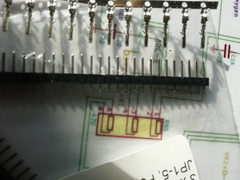
NO2C is all soldered up and a bit of basic bench functionality testing...
Have tested the map sensor and that is fine
Got the Ign1 and 2 to flash the leds through the test page in TS
Bit of a worry when the Inj 1 and 2 didn't respond...but applying 12v to the speeduino rather that just being powered from USB sorted that
out...
Batt voltage in TS is showing 4v higher than the actual bench supply voltage
I see it can be calibrated in TS ...but adjustment only allows 2v offset at most
I am guessing I either need to change the code, replace the resistors ...or live with it
Very unsure about the little mini multiway connector provided (not soldered it on as it doesn't look up to the task)
It is a LOT smaller than I had imagined and a couple of the pins I have tested feel quite loose
Not sure if I am better off soldering wires straight to the board to a more substantial multiway connector...more hassle to work on, but less likely
to give issues
Neat little board and not bad to solder up, took my time with it, happy with the way it came out...got to that age where I had to use a magnifying
glass and lots of light...sigh
Not sure what it is coated in, but using IPA to clean flux residue made it go very gooey and sticky...thankfully it has dried off, but left a
hazy/messy finish
I guess make some kind of stim for it next and more functionality checks and a proper case before I tear into the cars loom

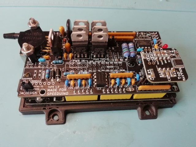
NO2C
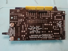
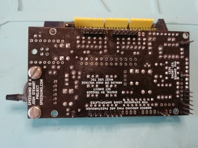
NO2C bottom
MikeR - 17/9/23 at 11:36 PM
Check if the connector is actually a pc power supply ATX 24 cable. Means you can buy an extension cable for not much and for you've got the
connector and 6 or 12" pig tail (once you cut the other end off). Saves lots of hassle.
robocog - 18/9/23 at 04:19 PM
Unfortunately it is not an ATX PSU connector...it is like one that has been shrunk in the wash
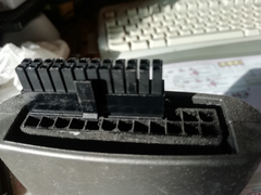

Mini ATX
Pins are same size as dupont pins!

compared to dupont
(just checked and the male dupont is an OK fit into the female ...infact maybe a slightly tighter fit than the ones in the male plug end that would
get soldered to the board)
They simply look too skinny and not enough surface area to carry any current TBH
I know that the igniter outputs and sensors wont need to pass much current...but in the MS I was using DB37 and inj outputs are using 2 pins each to
share the current
I am thinking of doing the same and using a DB37 to wires direct soldered to the board...and again maybe share a couple of pins for the injectors as
that is something that has never let me down ....yet
The female connectors in comparison with DB37 male pins....
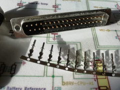

Female compared to DB37 male
My senses are saying that fitting the supplied plug will come back and bite me ...and be a real pain to remove later without lifting pads or damaging
stuff
Maybe fitting a full size ATX connector via a pigtail is an option....so you may be onto something with the ATX extender idea
BUT I do have a bunch of DB37's here already...will give it some serious thought
Using a DB37 on a pigtail and pinning it to reuse the loom I have is looking favourite
Just a bit shocked at how small and skinny the supplied connector is, maybe it would be fine and I am overthinking it
MikeR - 18/9/23 at 08:12 PM
Speeduino v0.4 board used an idc connector on the board. Lots of people questioned this. Josh did a video. It can handle the power, in fact the bit to
worry about is the traces on the board which are much smaller. Speeduino doubles up the injectors to two pins in case you are running batch injection
on a V8 (ie two injectors per channel).
MikeR - 18/9/23 at 08:16 PM
https://www.amazon.co.uk/Extension-Cable-Female-Supply-Optiplex/dp/B09NBK3Z4M
Would that work as a pigtail (if you cut the atx end of and stick with the mini atx end)
robocog - 18/9/23 at 08:58 PM
Traces are nice and wide (about 2mm??, not sure how thick ) for the stuff that is controlled from the transistors on the NO2C, but only got the
option of single output pins per bank
Was only when I compared to the DB37 plug pin sizes and realising that they are also using 2 pins for each inj bank to spread the load that I started
to get a bit twitchy
Looking at the Molex pages, and finding something similar... if not the same - I see they rate those at 8.5A per pin..and I am fused at 5A per pair of
injectors and have never blown one....so I am very likely worrying about nothing, but when comparing surface contact area , it just LOOKS wrong before
even talking about splitting the load across a couple of pins on the DB37 connector
I possibly went overboard on the size of connectors and wires to the injectors needlessly in the rest of the loom...big ugly white square connectors
with 6.3mm spades...
Normal to want to over engineer and overthink these things I guess...
Am torn now....
MikeR - 19/9/23 at 08:51 AM
https://www.google.com/url?q=https://m.youtube.com/watch%3Fv%3DTin42HBdE-Y&sa=U&ved=2ahUKEwjI5JnbpbaBAxU4XEEAHfZXA4AQtwJ6BAgDEAE&usg=AOvVa
w1bgzo5Q33o669E88M7cbb2
May or may not reassure you.
robocog - 24/9/23 at 07:04 PM
Still haven't decided, so have soldered in wires for now (easier to remove and go with the multiplug if I change my mind)
Hooked it up to a megastim - checked O2, TPS, CLT, IAT and that I had fuel pump output
All working great (but input voltage is showing as quite out of whack reading about 4v higher than a bench PSU - verified with a multimeter as well
...not sure if I need to deal with this or if it is a non issue, get an annoying red warning about input voltage when it sees a real 13 volts..and it
shows closer to 17v on TS)
Hooked it up to the car - calibrated the TPS, and I am getting sane readings from the other "real" sensors as well..
wired the VR up and did a tooth log and reversed the VR pins so I could see which way it was happiest... as advised.... (no filter applied)
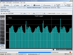
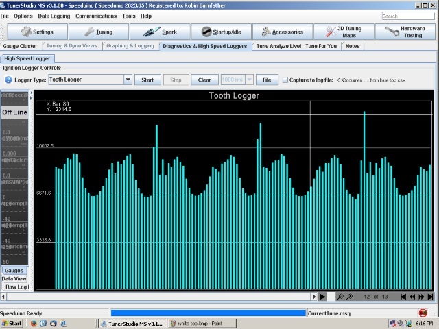
tooth log 1
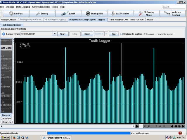
tooth log 2
I guess the bottom one gives the best signal ...and is the one with the positive wire from the VR on the bottom terminal on my sensor...cannot
remember which way they are wired
and I guess the dips are where the engine is pushing over compression in the cylinders whilst cranking over
Just awaiting a coilpack plug (forgot to order one) and I can get the ignition side loom sorted
Dug out a strobe light and verified it works (fired car up with the old MS unit)
Not got a timing mark as I changed the sump to an ERA one - so will have to find TDC and make a pointer and suitable set of marks and use that
All systems go, hopefully not too far off it starting with the speeduino...if all goes to plan
(and then the hard work of getting it running nicely)
I guess I can sort of transpose the 8X8 I have in MS and a kind of make new tables from the tables I have
I am guessing no easy way of "exporting and importing" due to the table size differences
As and when I get it running I am happy to share the msq...but I guess unless someone else is running the same TB's/injectors/regulator and pump
etc it will only be something to refer to rather than a plug and play setup
[Edited on 24-9-2023 by robocog]
MikeR - 25/9/23 at 10:23 AM
The second tooth log is what you're looking for HOWEVER its dependent on your VR sensor. You set your trigger edge to your VR sensor and then
adjust the wiring to look like the second picture. (this is a mantra for me as people get it wrong, then get issues with high rpm timing drift or bad
sparks and say "speeduino's rubbish" .
.
coyoteboy - 25/9/23 at 10:43 AM
quote:
Originally posted by MikeR
https://www.google.com/url?q=https://m.youtube.com/watch%3Fv%3DTin42HBdE-Y&sa=U&ved=2ahUKEwjI5JnbpbaBAxU4XEEAHfZXA4AQtwJ6BAgDEAE&usg=AOvVa
w1bgzo5Q33o669E88M7cbb2
May or may not reassure you.
Not really, voltage drop is key, not so much heating. Injectors need a low impedance path and dinky little wires don't help. Nor do unnecessary
connectors which each have a few tens of miliohms across them and potential for variation in performance. Someone in the comments points out that you
need a predictable low voltage drop to accurately control them, if the voltage drop in the harness changes with time, temperature or current, it makes
tuning tricky. But everything is a compromise.
scudderfish - 25/9/23 at 07:46 PM
quote:
Originally posted by robocog
I guess I can sort of transpose the 8X8 I have in MS and a kind of make new tables from the tables I have
I am guessing no easy way of "exporting and importing" due to the table size differences
[Edited on 24-9-2023 by robocog]
You can export specific tables in TS, and then import them. It will interpolate the data to the new size
robocog - 28/9/23 at 03:19 PM
Awesome!
I have kind of interpolated the ignition and fuel map, and bunched the TPS loads up where I feel I needed more cells than relying on interpolation
gave with MS (again could be barking up the wrong tree as to the sole reason for going with speeduino over MS)
majority of the axis is taken up with 0% to 50% load, then bigger jumps to 100% load...
Bit more progress today
- got the loom made up for the ignition driver, hooked it all up and tested I have spark
Marked the front pulley and confirmed it was firing in roughly the same place as the edis was...
(swapped between MS and Speeduino whilst it is still trivial to do that)
Hoping tomorrow is OK weather wise and I can get the injectors wired in and see if I can make it "run" and get tuning
I need to make proper marks at TDC and 10 degrees to confirm it is advancing etc and get it dialled in properly, but much easier if it is actually
running
Not got a case for it yet, so its a bit precarious/sketchy and just dangling from the loom plug, so unlikely I will be taking it out for a test drive
with speeduino just yet
getting closer though.....
MikeR - 28/9/23 at 04:21 PM
I should be certain of this but I'm only 95% sure.
Cranking timing over rides locked ignition. So if you're spinning the engine slower than the cranking limit the advance won't be the
ignition fixed advance.
Hopefully that will stop you chasing your tail trying to figure out the timing.
robocog - 28/9/23 at 07:27 PM
Yes, cranking was quite slow, so not that easy to see, but looked to be in the ballpark(ish)
(I set to fixed 10 degrees...but as you point out it could have been at the cranking advance angle of 5...and I bet I am still a few degrees out on
the pickup, It sure looked close enough to the 10 degrees I was getting from the EDIS to at lest try and start it)
Have wired up the injector pins to the connector tonight, so hopefully if the weather is OK tomorrow I may get to attempt to start the car and double
check the timing
Will 3d print a case shortly, so /if/ I get that far tomorrow and am tempted to take it for a drive round the block it will be less sketchy
Should I be concerned about the misreporting of input voltage?
Only things I can see it affecting off the top of my head are the deadtime compensations and dwell compensation...but maybe there is more "behind
the scenes"
On a bench PSU (verified with a multimeter as well)
10v is showing as 12.4v in TS
11v = 13.9v
12v = 15.3v
13v = 16.7v
14v = 18.2v
This is after using the calibrate voltage offset reading in TS and reducing it to the max -2v...
robocog - 28/9/23 at 11:04 PM
and that was short lived
Just couldn't live with the wrong voltages being displayed...so got the firmware, modified the sensors ini and compiled using VS code
TS whined that versions didn't match, tried with arduino IDE...same issue...
downloaded another version of the firmware, used arduino studio, got the voltage almost dead nuts on...went back in and made a minor tweak and slowly
swept from 10v to 13v making note of the reported voltages (same as I had been doing when dialing in to get the reported voltages close...the
speeduino stopped responding,....loud pop - and C4 exploded and has stunk the room out
was only seeing 13v...so kind of glad it didn't do this after fitting to the car
Bit gutted TBH...not sure what to do now...
MikeR - 29/9/23 at 06:37 AM
I let the magic smoke out my first one that I soldered up. I then bought one pre made. Had no issues with that one. Go on the forum or Facebook or
discord and ask questions. Worst case send it to Richard bell on Facebook or eBay and he'll repair it.
robocog - 29/9/23 at 08:07 AM
Maybe all is not lost
It still seems to work / respond this morning, tested using stim on the bench....
Dug into the schematic, looked the board and arduino over for any "reasons" or witness marks etc...nothing found
The C4 cap is part of the inlet side for the 5v regulator
(I am guessing for suppression/smoothing)
Have desoldered it out of circuit and will carry on regardless for now
I just don't know why it decided it had had enough at 13v...it will potentially see more than that when installed in the vehicle!
Hoping just a bad component - as it was on a decent lab PSU and unlikely it would have put out anything other than what I told it to...
(looks at PSU suspiciously....)
Case has printed, voltages are now being reported accurately for everything between 10 and 14v after a recompile with new offset in sensors ini
Mine needed 254 to be changed to 170 to get it reading right...not sure why such a variation..but it is what it needed to be to read right
------------------------------------------------------------------------------------------------------------------------------------------------------
------------------------------
void readBat()
{
int tempReading;
#if defined(ANALOG_ISR)
tempReading = fastMap1023toX(AnChannel[pinBat-A0], 170); //Get the current raw Battery value. Permissible values are from 0v to 24.5v (245)
#else
tempReading = analogRead(pinBat);
tempReading = fastMap1023toX(analogRead(pinBat), 170); //Get the current raw Battery value. Permissible values are from 0v to 24.5v (245)
#endif
------------------------------------------------------------------------------------------------------------------------------------------------------
--------------------------------
I am running with speeduino-202207-fixes firmware as it was the only one that I could get TS to work with nicely after compiling
I tried with what I thought was the master, but ran into signiature issues as it was adding -dev to the name....
How do I change it? (can it be explained in a way that I would be able to understand?) TS's error message was not that helpful despite it
offering me to click a button to try and fix the conflict...the only 2 buttons that seemed to get me out of the loop was cancel or carry on but
ignoring the issue, which would repeat next power cycle
sky is grey but not yet raining...today is the day I guess... unless anything else goes wrong!
Will hopefully report back with good news!
MikeR - 29/9/23 at 08:16 AM
If you use the Dev firmware you need to tell tuner studio is on Dev. The name check is to ensure the mapping of fields in Tibet studio matches what is
on the arduino.
If you press ctrl-p in tuner studio (you can get there from a menu but I can't recall which one or during new project setup) and browse for the
ini file. it's in the folder listed before the speeduino folder with the source code. It's called speeduino.ini.
Doing this from phone at work so can't check actual locations.
robocog - 29/9/23 at 11:44 AM
Car starts and runs fine
Sun has come out in full force so I cannot see the laptop screen without sitting under the tonneu cover, so have come in to cool down
Too bright out there to see the strobe light, so will have to wait for another day...or to get an opportunity to take it indoors somewhere
I have confirmed the timing is moving and is very much in the same ballpark as EDIS was giving when locked to 10 degrees
Car revs up OK and seems to behave - but does still need a load of tuning
Car still "wants" to run quite rich at idle - seems "happiest" and smoothest in the 12's, if I lean it out from there it
gets a bit lumpy and revs start dying
Still have a lean patch with very slow throttle tip in from idle (same as I had with MS)
(not sure how to combat this - other than don't do that...)
maybe I can shuffle the fuel table a bit more and keep tuning that area...
But - major success I'd say
Still got to do a load of routing and tidying up of wires
also need a proper case as my 3d printed one is a bit chonky and doesn't have a lid yet and make some kind of decision whether to fully replace
the MS - or try and have it so they can be swapped out with little to no fuss till I have it fully under control
I will try and link to the msq for anyone else wanting a nosey at a mostly working but not tuned zetec speeduino looks like
(2l silvertop, R1/R6 throttle bodies, Bosch200 series igniter, zetec coil)
http://www.robocog.co.uk/speeduino/Zetec_silvertop_speeduino_starts_and_runs.msq
[Edited on 29-9-2023 by robocog]
[Edited on 29-9-2023 by robocog]
MikeR - 29/9/23 at 12:58 PM
Post your tune and a log on the speeduino log location and then ask for help on the forum / facebook. People will have a look and offer advice.
I'm nervous by your voltage the more i think about it - you shouldn't need to edit the code. Can you double check the battery voltage
circuits as it should 'just work'. I'm worried it has side effects.
robocog - 29/9/23 at 03:22 PM
Yes, it bothered me - to the extent I wanted to make changes to the code to make it "right" (computers doing calcs - BS in = BS out)
I know the voltages going in were clean (lab PSU, verified with multimeter)
Not much in the circuit on the NO2C for VCC power coming in
3 resistors, 2 capacitors then going off to ADC clamping and pin A1
I guess I /could/ have played with the voltage divider resistors to get the arduino to recognise closer to the actual input voltage, but the software
route seemed less likely to lift pads, plus was more of a learning curve 
The cap (tantalum?) that blew is on the batt power input going to the 5v reg, I have a good steady 5v from it, so I don't think that the reg
caused it - or got harmed
Have messaged diy-efi where I got it - and asked about me having to recompile for input voltage to be right
(and to see if he is willing to chuck me another cap to try...and to let him know this has happened in case there is a correlation with something)
Will see what he says...he has got back to me on other queries after a few days
My guess is that not all mega's are equal and it /could/ vary - based on internal reference voltages etc...and I possibly got one that was a
"bit more off" than the 2v +/- adjustment available that TS allows...
I think I am pretty confident that it must have just been a bad cap that had a premature death...
A google search brought me to doing the firmware recompile as a workaround, so I am not the first that has needed to do that
(but was a bit surprised it was so far out)
Will do some more tuning when I get chance (need a dull overcast day) before posting anything to the speeduino site/facebook
Would be happier sharing the tune once I have run it through autotune a few times at least
Have decided I will try and add the extra wires to the DB37 that I will need for speeduino...that MS doesn't use - so swapping ECU's is
fairly trivial
(confident I have enough extra "spare" pins in there that are not connected or used in the MS unit)
1, 2, 27, 29 and 31 for VR+, VR-, Ign1, Ign2 and Tach out...
Will dig out the old MS board schematics and double check first
robocog - 29/9/23 at 06:07 PM
Just a theory (on why my cap may have gone pop...)
I was using USB /AND/ a lab power supply at the time
I wonder if that could have been a cause?
I had run it up this way quite a few times already (stimulator also supplies VCC) whilst playing with it on the bench and I didn't consider that
powering from USB and the VCC simultaneously may be an issue..mind you same issue when I was playing with it on the car ...
Do I need to make a special USB that does not supply power? (data only)
MikeR - 29/9/23 at 06:38 PM
Nope. It's happy with both. That is the norm. However, every time it detects power on USB it triggers a reset on the Arduino so it can(if needed)
update. If you have a cable or something to block post it means your can connect without causing a reset.
robocog - 29/9/23 at 08:30 PM
Bang goes that theory then....
Was hoping it may give a reason for the cap exploding and give me something to avoid for next time...
robocog - 30/9/23 at 10:42 PM
It lives...
A few hiccups along the way, but I drove it about for a good couple of hours today doing some tuning
Old mapping seemed OK on the driveway without load... but was obviously not perfect as soon as I hit the road..LOL
Had a few moments where it fell flat on its face from low revs, have got it so it doesn't do that (manually) and locked those bins out from
autotune...again it seems to be initial tip in from low RPM...it likes to run rich at idle and I have not really reflected that in the AFR bins, so
autotune kept leaning it out making the tip in issue worse
I think I have been a bit stingy with my AFR bins around cruise, so will richen them up a bit, so all the issues have been of my doing
Have got it to the point where it is pretty much usable and is perfectly happy with a hot start
(yet to see how it takes to a cold start)
Tuning not quite as refined as I had MS ...yet, but not bad for a couple of hours of playtime
Autotune has been pulling fuel out mainly, so am satisfied it should be OK to hit some of the higher RPM/load sites gradually
(was trying to hit a bin and hold it there, till it had worked its magic, then move to another bin..as well as just normal pootling along in
traffic)
Might get chance to try and hit a few more bins tomorrow with more autotune runs
(quiet dual carriageway run is on my list so I can perhaps hit some of the higher RPM sites)
Will keep prodding at it and post up a new msq on here when I am closer to being happy with it...
All in all - am dead happy I have gone this route
MS is still in the car and I have it so I only need to swap VR sensor and coil plug and a power wire and the vacc tubing and I can swap over the
ECU's
(just whilst I am experimenting)
MikeR - 1/10/23 at 06:21 AM
Fabulous news. This is great to hear.
If I'm correct, the tip in has had a few grumbles for not being great and their is a revision.. not sure if it's in the current firmware of
the next release.
robocog - 4/10/23 at 02:20 PM
Not heard back from diy-efi, so have just ordered 5x replacements from an online retailer (not that I have spotted any issues with running without C4
for now)
Did the timing today - printed a timing wheel, cut it out, laminated it, bluetacked to the front pulley, bent wire around a bolt as a pointer
Cam cover off to check the cams are right (and that I had the "right" TDC), dial gauge down the plug hole
I was miles out
Took my time and got it absolutely spot on for the ECU, did some autotuning...world of difference
Engine has never run so well
I have replaced that MSQ I shared earlier, as the trigger angle was NOT right
For my silvertop engine running a NO2C speeduino - the trigger angle is 287degrees
(but always check for yourself ;p)
[Edited on 4-10-2023 by robocog]


