omega 24 v6
|
 posted on 9/11/08 at 11:33 AM posted on 9/11/08 at 11:33 AM |

|
|
Megasquirt woes
Hi all hopefully you can explian the following to me. I have made a possible error on my megasquirt unit MS1 V2.2 board. I put a fuel pump relay in
the relay board and it looks like I may have done some damage. The relay had a built in diode across the coil (reverse emf or suchlike protection) and
now the fuel pump will not run at all. It does not prime for 5 secs (or whatever) and it does not run once the engine is turning over ( as it used
to). I have changed Q3 and still no difference and i'm begining to think that I may have damaged the processor. I'm not a novice to
electrics but electronics are not my thing. I cannot for the life of me get my head round the transistorQ3/Diode D7 /resistor r13 circuit and I was
wondering if someone would be so kind as to explain it to me in general terms so that I can make a judgement on what to do next.
If I have done damage where is it likely to be?? I retested the unit as per the build instructions yesterday and all seems to be ok regarding the
power, serial input and clock circuits. i could rig up a stand alone relay for the fuel pump and see if it works but I really want to succeed with my
megasquirt. It's fighting me tooth and nail at the moment though. Thanks in advance.
If it looks wrong it probably is wrong.
|
|
|
|
|
02GF74
|
| posted on 9/11/08 at 11:53 AM |
|
|
link to circuit diagram?
|
|
|
omega 24 v6
|
| posted on 9/11/08 at 12:08 PM |
|
|
Ooops that would help. Here it is page 3 of the pdf.
megasquirt schematic
If it looks wrong it probably is wrong.
|
|
|
02GF74
|
| posted on 9/11/08 at 12:44 PM |
|
|
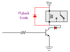
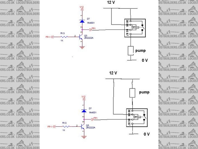
I assume V12 is the 12 V power supply.
Circuit is equivalent to 
As you correctly say, the transistor Q3 is a simple on/off switch load connected to FP-1 with the fly-back diode D7.
The load is inductive e.g. a relay, motor and the diode clamps the votage to V12 due to back emf generated when the supply to the load is turned
off.
- prevents damage to transistor.
The transistor switch is controlled by the microprocessor on pin PTA0.
Are you able to measure voltage on pin PTA0 when MS tells pump to be off and pump on? (with pump disconnected).
"Pump on" should show 5 V, "pump off" 0 V.
You can then connect a resistor (any value between 470 and 1 K) to 12 V to a LED to FP1 and repeat - the diode would light when MS tells pump to be
on.
note: google tells me that 2n2222a transistor has max current of 800 ma - That is too low to drive a fuel pump directly - is there not meant to be a
relay for the fuel pump?
|
|
|
omega 24 v6
|
| posted on 9/11/08 at 12:58 PM |
|
|
It is driving a fuel pump relay only as you say. In fact exactly as you have drawn. But the diode you show is on the megasquirt board I fitted a diode
version of the relay to try and get rid of line noise from the pump. Ever since that the pump refuses to run at all. I could connect it all up and
measure the voltages later on no problem.
ETA the relay in miy mind is a switched negative I.e the VCC part of your diagram goes to the neg side of the relay coil. I put a diode across that
relay from 85 to 86 to stop any emf going back to the ign wire (pin 85 IIRC) and causing false ign triggers. I think I might have been a bit premature
in trying this.
[Edited on 9/11/08 by omega 24 v6]
Also edit to add that the diode i put in is doing the exact sane thing as the one on board???? WTF have i done
[Edited on 9/11/08 by omega 24 v6]
So at the time of problem arrising it looked like this. So even if I connected the diode the wrong way round nothing bad should have happened??
 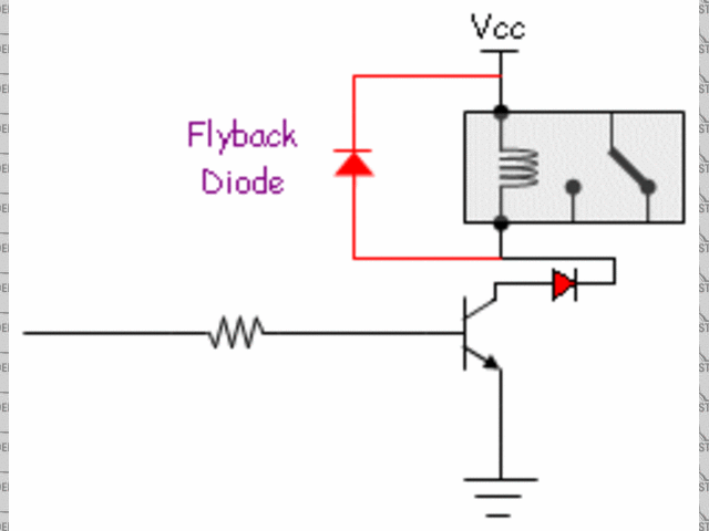
Descripflyback diode
[Edited on 9/11/08 by omega 24 v6]
[Edited on 9/11/08 by omega 24 v6]
If it looks wrong it probably is wrong.
|
|
|
02GF74
|
| posted on 9/11/08 at 01:32 PM |
|
|
The driver Q3 switches the load to 0V so the other end of the relay coil is connected to 12 V, as in the diagram. Note pins 85 and 86 need to be
connected like this due to the internal flyback diode.
The pump can be connected in either way; the relay contacts complete the curcuit.
If the pump body is 0v contact, then you need to use the top circuit or isolate the pump from the bodywork.
1 question - you say you fitted a relay with built in doide then mention putting a doide across the relay - is this an additional diode? and whcih
way round was the diode fitted?
Rescued attachment pump.JPG
|
|
|
rachaeljf
|
| posted on 9/11/08 at 01:32 PM |
|
|
Omega,
What you are saying sounds a bit confused; Vcc is the 12V supply to MS, which should be controlled by your ignition switch. If you insert a
"diode fitted" relay, you have to be careful to connect it the right way round. The diode inside the relay has to "point"
towards the 12V side, same as D7 points towards Vcc. If you connect it the other way round, as soon as MS commands "pump on" Q3 will be
smoked, because Q3 is effectively shorting 12V to ground via the offending diode.
The upshot is: don't use a diode fitted relay! Noise from the pump won't be coming via the relay coil anyway, and a adding a diode
won't help. If your pump is that noisy, fit a suppression capacitor to the pump 12V terminal, as close to the pump as possible, with the
capacitor earthed to the car's chassis nearby.
You will be unlucky if you have damaged the processor as the 1k resistor R13 should provide enough current limiting to protect it I would think.
Best of luck! R
Edit - if you have an extra diode connected as per your diagram, the pump definitely won't work as the extra diode is blocking any current going
though Q3, so it can't switch anything!
[Edited on 9/11/08 by rachaeljf]
|
|
|
02GF74
|
| posted on 9/11/08 at 01:38 PM |
|
|
Descripflyback diode
If that is how you have the cricuit, the relay coil won't work as the red/black diode you have fitted will not allow current to flow.
|
|
|
omega 24 v6
|
| posted on 9/11/08 at 02:20 PM |
|
|
My mistake. It was wired as per O2gf74's last double diagram the top one so I could have done damage but I have replaced the
transistor.
Where does v12 go then on the board??and what is it's purpose?? it wont allow current back through the diode D7 but it would have let current
through IF i'd connected up the diode in the relay the wrong way round. To clarify the position I put a diode over the terminals I t did not and
does not exist within the relay itself.
If it looks wrong it probably is wrong.
|
|
|
rachaeljf
|
| posted on 9/11/08 at 05:15 PM |
|
|
v12 is Vcc, just different notation to confuse you! Vcc is the 12V rail on the MS circuit board. It is connected to pin 28 on the 37 way plug, which
you need to connect to the ignition switch so MS is powered up only when you switch on the ignition.
D7 is there to deal with the high voltage spike that a relay coil always creates when you switch it off. This spike can be 50V or more, and it could
damage the MS components and board. D7 protects MS (in particular Q3) by directing the high voltage back into the ignition supply wire (via Vcc rail
and pin 28 etc.), which is connected to the other end of the relay's coil. So, as long as the coil spike voltage is greater than 12V, the spike
current just recirculates harmlessly through the coil and D7 until it decays.
You don't need to add any other diodes to the relay; D7 will do the job. Your noise issues originate from elsewhere.
|
|
|
omega 24 v6
|
| posted on 9/11/08 at 07:13 PM |
|
|
Ok so let me summarise what I've learned from this.
I may have supplied 12volts to the Q3 tranny
I may have damaged the Q3 tranny ( but I did replace it)
The fuel pump relay is grounded when a 5 volt supply is applied to the pin2 (diagram) and allows the pump to run.
If there is no 5 volt supply and the resistor is intact then the processor is fubared
The noise from the fuel pump may be reduced by fitting a capacitor to it as close as possible (but what type and size???)
I must not be a tit and muck about with things before I understand them completely.
Many thanks to all for they're input I'll let you know what happens when I get round to checking it all out.
If it looks wrong it probably is wrong.
|
|
|
02GF74
|
| posted on 10/11/08 at 07:19 AM |
|
|
quote:
Originally posted by omega 24 v6
I may have supplied 12volts to the Q3 tranny
If you mean you applied 12 V directly to FP1, then Q3 would not be happy about that for sure.
I may have damaged the Q3 tranny ( but I did replace it)
We assume the same type was fitted in exatly the same orientation and that you allowed a bit of time between soldering each leg for the
joint to cool. You could try TIP122, from Maplins, it can take twice the voltage but the flyback diode should protect it.
The fuel pump relay is grounded when a 5 volt supply is applied to the pin2 (diagram) and allows the pump to run.
When the micro supplies 5 V on FP-1, the transistor is turned on. It will allow current to flow through the relay coil if one end of the
relay coil is connected to 12 V and other to FP1 - assuming that a relay without internal diode is fitted, if it has internal diode, the orientation
of the diode inside the relay must be in same was as the one on the board.
If there is no 5 volt supply and the resistor is intact then the processor is fubared
It would appear so. To be 100% sure, ensure that the transistor is working and there is nothing connected to FP1, probably best to remove
the transistor and measure voltage at FP-1. If it is never close to 5 V, the output pin on the micro has gone to silicon heaven. The mirco is
reasonably cheap, less the £ 10 is my guess. There may be another I/O pin you could use but would require changes in the software.
The noise from the fuel pump may be reduced by fitting a capacitor to it as close as possible (but what type and size???)
Try something like a 0.1 uF capacitor, the condenser (old term for capacitor) from a points distributor already will have the leads and
tabs so should be easy to fit without soldering. Alternatively one of the suppressors fitted to alternators. You would wantto be sure you fit them
the right way round, usually the capacitor body is earth. You also want to ensure the negative ofthe point has good earth and the body is earthed too
- see my post earlier about connecting the pump.
|
|
|
omega 24 v6
|
| posted on 10/11/08 at 12:43 PM |
|
|
Many thanks 02GF74 for your time and everyone else's on this At least I now know what should be happening now. I'll let you know when I
find out what it is.
If it looks wrong it probably is wrong.
|
|
|
Benzine
|
| posted on 11/11/08 at 08:46 AM |
|
|
I'd be interested to know what you find out, I think I have the same problem. I wired up MS wrong the first time round and put power through the
wrong connection. Now that it is wired up right the fuel pump isn't coming on
|
|
|
martyn_16v
|
| posted on 11/11/08 at 09:13 AM |
|
|
quote:
Originally posted by Benzine
Now that it is wired up right the fuel pump isn't coming on
How much testing have you done? This could be normal behaviour, MS won't run the fuel pump until it starts recieving an rpm signal, unless you
have configured a priming pulse in which case you'll get a brief run at power up.
|
|
|
Benzine
|
| posted on 11/11/08 at 11:09 AM |
|
|
quote:
Originally posted by martyn_16v
quote:
Originally posted by Benzine
Now that it is wired up right the fuel pump isn't coming on
How much testing have you done? This could be normal behaviour, MS won't run the fuel pump until it starts recieving an rpm signal, unless you
have configured a priming pulse in which case you'll get a brief run at power up.
Priming pulse, eh? Is there an option somewhere in megatune to turn that on?
EDIT: this shizzle?

[Edited on 11/11/08 by Benzine]
|
|
|
omega 24 v6
|
| posted on 11/11/08 at 12:44 PM |
|
|
It's In crank/warmup>cranking settings
If it looks wrong it probably is wrong.
|
|
|
Benzine
|
| posted on 11/11/08 at 01:05 PM |
|
|
Ahh yeah thanks, found it. Was set at 6ms (i've never touched it so I presume this is default) and still no life from the fuel pump. T_T
|
|
|
rachaeljf
|
| posted on 11/11/08 at 02:43 PM |
|
|
Hmm, there's a "priming pulse" and a "priming pulse", as it were. On later versions of MS, the controller runs the pump
for a few seconds when you first switch on the ignition. This is to prime/pressurise the fuel system. Then the controller gives a priming pulse to the
injectors, of a few milliseconds, to prime the cylinders.
What version software have you got?
|
|
|
omega 24 v6
|
| posted on 15/11/08 at 08:57 PM |
|
|
Well i finally got round to it today. The squirt SEEMS to be working fine on the bench with it's own engine pigtail so we'll see what
happens when it's back in the car.
One thing that's bugging me though perhaps someone can explain.
On the VR conditioner board (homemade) the vr return (not the screen) comes back to ground. I cannot see the logic in the method of grounding. As the
signal is an ac sine wave then presumeably at certain points during the cycle the said ground cable has a positive potential. If it's grounded
near or along with the transistor earths or outputs for coil (vb921) then I supose there is room for problems to occur??
If the return from the vr is just that i.e. a grounded cable then why does it need to be there at all?? why not just terminate it at the crank sensor
point??
Anyone??
If it looks wrong it probably is wrong.
|
|
|