beaver34
|
| posted on 8/12/08 at 07:35 PM |

|
|
speedo
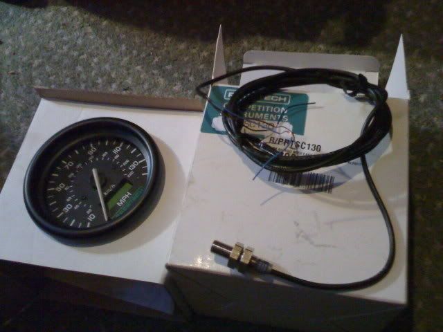
hi there, i have a race tech speedo to fit to my car, i also have a fitting kit, but am unsure where to attatch the pickups etc.... any help would be
great, thanks al
|
|
|
|
|
scootz
|
| posted on 8/12/08 at 07:44 PM |
|
|
Sorry - I'm not much use... I just came on as I thought it was a post about swimming-trunks!
There's nothing that I couldn't tell you about those speedo's!

PS - Don't worry... someone will be along shortly to help you out!

|
|
|
beaver34
|
| posted on 8/12/08 at 08:10 PM |
|
|
quote:
Originally posted by scootz
Sorry - I'm not much use... I just came on as I thought it was a post about swimming-trunks!
There's nothing that I couldn't tell you about those speedo's!
PS - Don't worry... someone will be along shortly to help you out!
thanks buddy! and if you wish ill make my next thread about trunks!
|
|
|
austin man
|
| posted on 8/12/08 at 08:25 PM |
|
|
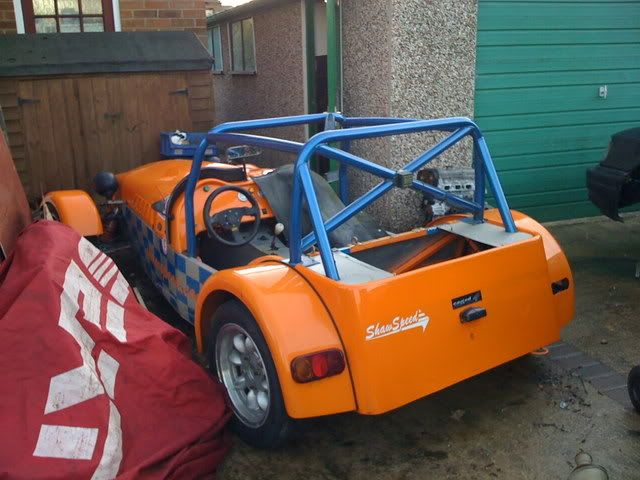
what are you bulding ?? you can glue the magnet to the CVjoint exiting the Diff and make a bracket to suspend the sensor from this is usuall attachet
to the chasis if a seven type of chasis. Did this with the brotherin laws MK not had any problems in the last 3 years
|
|
|
02GF74
|
| posted on 8/12/08 at 08:37 PM |
|
|
luckily for you Racetach speedo trunks are my specialist subject, even though I haven't been to the pool since August.
the easy bit.
black wire = 0 V
green = 12 V switched from ignition
red/white = 12 V to side lamps i.e. instrument illumination
the not so easy bit.
white/black - this needs a signal switching between 0 V and at least 8 V - I am supplying 9 V.
red/blue - this is for low voltage senders; I did not test this but suspect it work on much lower voltage, possible as low as 1 V (guess work)
I did not use a fitting kit but made my own sender based on hall effect device.
You mention you have magnets so either you have hall effect (this would need a sender with 3 wires) or a reed switch (a sender with 2 wires)
lemme see what I can find about the racetch sender and get back to ya; if you can post a photo and write any info. about the instruction you have,
then that would help.
I am using RTSC 130 model that I suspect means nothing more than Race Tech Speedo C??? , 130 being indicate mph.
[Edited on 8/12/08 by 02GF74]
|
|
|
scootz
|
| posted on 8/12/08 at 08:39 PM |
|
|
Told You Told You Told You (that someone would be along shortly with the 'knowledge' ! !
|
|
|
02GF74
|
| posted on 8/12/08 at 08:51 PM |
|
|
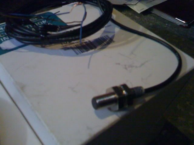
apparently it is hall effect and looks like this:

interesting connector and I can see two wires - black and white; would have expected 3.
anyway, the hall effect sender needs 3 wires: power, 0 V and signal. (the 0 V may be made via the body of the sender?)
you need to identify which wire is for which and connect signal to the white/black wire; move magnet to and fro in front of the sender and see what
the dial does; otherwise use the red/blue. (the speedo would need to be powered up).
something to consider; you can buy from Rally design adapter to fit speedo drive in Ford gearbox and then fit a Ford speed sender - a nice solution if
you have the space instead of attachig magnets and making brackets for the sender.
I amde my own adapter for the 4 spd Ford gearbox from aluminium tube, brass, shaft, a bearing and slotted wheel, wasn't elegant but works.
[Edited on 8/12/08 by 02GF74]
|
|
|
beaver34
|
| posted on 8/12/08 at 10:15 PM |
|
|
here is what i have,
a can get my head around the wiring part, but how does the magnet thing work?
and is this car
|
|
|
02GF74
|
| posted on 9/12/08 at 10:18 AM |
|
|
quote:
Originally posted by beaver34
a can get my head around the wiring part, but how does the magnet thing work?
inside the sensor is a semi-conductor device that uses Hall effect to detect the presence of a magnetic field. there is additional circuitry to
amplify the signal.
when you bring a magnet close to the sneder, the voltage from it should change from when there is no magent near to it.
Am I correct that I am seeing 3 wires: blue, black and brown?
there should be instructions on what each wire should be connected.
my guess would be black = 0 V, blue = supply, 12 v? and brown is signal.
there should be instructions for this, if not, then you need to contact seller to find out as you could damage the sensor.
|
|
|
BenB
|
| posted on 9/12/08 at 11:50 AM |
|
|
I hope you have got a better one than the ones that used to be sold as Racetech (branded AST though!!).
They were the ones with the
sensor. Those speedos were a PITA to try and get to work because they had very precise requirements. The speedo had some slight adjustability(!) but
the odomoter required a specific 833Hz@100mph. In the end the only way for me to get it to work was to get a trigger wheel made up which clamped under
the rear Lobro bolts at the diff end. Hopefully the one you've got is better- ie fully adjustable and a 3-wire hall effect type (the old ones
were 2-wire only and variable reluctance)....
|
|
|
BenB
|
| posted on 9/12/08 at 11:52 AM |
|
|
info@racetechdesign.com might be able to give you the answer you require....
|
|
|


.jpg)