Irony
|
| posted on 3/7/12 at 07:46 PM |

|
|
Help wiring in tell tale??
Just trying to wrap my head around the wiring on my car. This is the circuit diagram for the fan unit. Its attached to Perm Live (as recommended by
the Complete Kit Car electrics book) and it comes on via a sender or a dash override.
How do I wire a tell tale lamp on the dash when I throw the dash switch?
Cheers
[img]
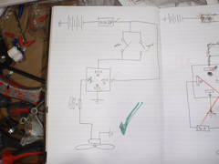 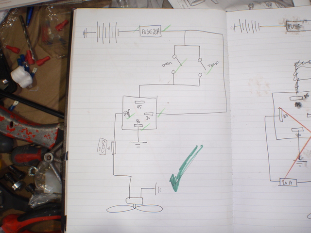
Description
[/img]
[Edited on 3/7/12 by Irony]
|
|
|
|
|
Toprivetguns
|
| posted on 3/7/12 at 07:48 PM |
|
|
Id wire a lamp in series with your switch. Soon as you switch on the fan, you switch on the tell tale.
Only drive as fast as your angel can fly... !
|
|
|
Westy1994
|
| posted on 3/7/12 at 08:01 PM |
|
|
If that were mine, I would be wiring a lamp after the inline fuse that feeds the fan, that way when the lamp is lit at least you know that the
electrics up to that point are working correctly, helps mainly for fault finding at a later date.
Just my 1p worth..
ETA - also useful for telling when the sender is active whilst driving - added peace of mind for me..
[Edited on 3/7/12 by Westy1994]
|
|
|
me!
|
| posted on 3/7/12 at 08:51 PM |
|
|
Not a critism- just a question as I'm doing basically the same thing at the moment. Is the second fuse between the relay and the fan redundant
if the circuit is already fused pre-relay? Or do I need to add in an extra fuse?!
|
|
|
big-vee-twin
|
| posted on 3/7/12 at 09:20 PM |
|
|
That arrangement means the switch should be rated at 20 amp too.
Take a wire from pin 87 on your relay and connect it to one side of a lamp earth the other side so it lights whenever you throw the switch or the
thermostat kicks in i.e. fan running light
[Edited on 3/7/12 by big-vee-twin]
Duratec Engine is fitted, MS2 Extra V3 is assembled and tested, engine running, car now built. IVA passed 26/02/2016
http://www.triangleltd.com
|
|
|
britishtrident
|
| posted on 3/7/12 at 09:22 PM |
|
|
Keep it simple.
You don't need a tell tale you will hear the fan.
Come to that you don't need a dash switch just more to go wrong, choose the correct temperature rating switch job done.
[I] What use our work, Bennet, if we cannot care for those we love? .
― From BBC TV/Amazon's Ripper Street.
[/I]
|
|
|
rachaeljf
|
| posted on 3/7/12 at 09:22 PM |
|
|
quote:
Originally posted by Toprivetguns
Id wire a lamp in series with your switch. Soon as you switch on the fan, you switch on the tell tale.
Careful! The above will light your lamp but only allow the lamp current (~0.2A) through the fan motor!
You need to wire your lamp in parallel with your fan motor. Then the lamp will light whenever the fan motor is powered (can't guarantee
it's running though!), whether via the thermoswitch or your manual switch. The way you have it wired you can't separate out a tell-tale
for your manual switch alone, unless you use a diode or two relays.
Delete the fuse between relay and fan motor; it's redundant.
Cheers R
Edit - brit-trid is right really, you shouldn't need a manual switch if you set up the cooling system properly!
Edited again - apologies to Toprivetguns, I misread your post. However, having a lamp in series with the switch may not allow enough current to
operate the relay so there is still a problem with that.
[Edited on 3/7/12 by rachaeljf]
[Edited on 4/7/12 by rachaeljf]
|
|
|
02GF74
|
| posted on 3/7/12 at 09:46 PM |
|
|
firstly you battery is wired to ground - positive - the long dash is connected to earth but I assume this unfamiliarity with the symbols than actully
wanting to short the battery!!!

for lamp, wire from pin 85 to pin 86 or a suitable earth.
|
|
|
RoadkillUK
|
| posted on 3/7/12 at 09:49 PM |
|
|
If you use a double pole switch for the manual fan switch, you could run one pole to the relay and the other to a lamp.
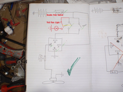 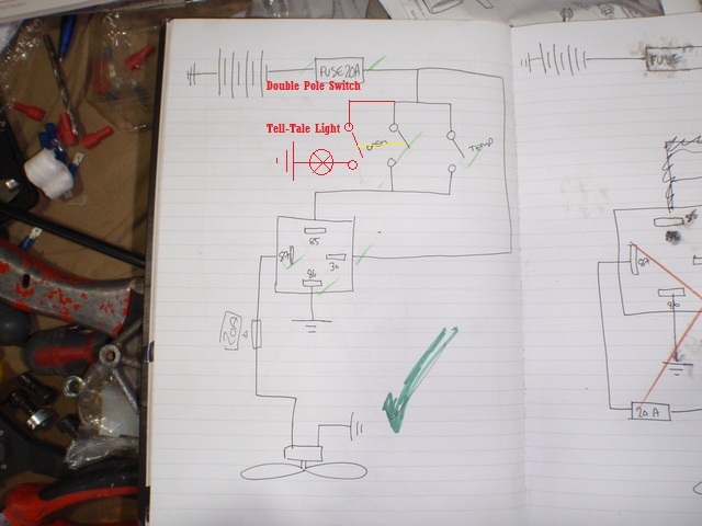
Irony
[Edited on 4/7/12 by RoadkillUK]
Roadkill - Lee
www.bradford7.co.uk
Latest Picture (14 Sept 2014)
|
|
|
Irony
|
| posted on 4/7/12 at 09:01 AM |
|
|
Thanks for the replies - you have got me worried now.
quote:
Originally posted by big-vee-twin
That arrangement means the switch should be rated at 20 amp too.
[Edited on 3/7/12 by big-vee-twin]
If the above statement is correct then I have misunderstood the wiring completely. I designed the circuit so the switch didn't need to have
high amp rated switch. The whole point of the relay is so you don't have 20amps running through the dashboard is it not?
I have designed the cooling system so I should never need to use the dashboard switch. But I have been told by a couple of serious mechanics that its
a good thing to have. I am a complete novice with car building so I lean towards safety first just in case.
If I wire a telltale in Paralelllele to the fan then the light will come on whenever the fan does. Being as the light will only draw 0.2amps and the
fan 20amps is this safe?
My symbols are not so hot!
Thanks
|
|
|
rachaeljf
|
| posted on 4/7/12 at 09:30 AM |
|
|
quote:
Originally posted by Irony
Thanks for the replies - you have got me worried now.
quote:
Originally posted by big-vee-twin
That arrangement means the switch should be rated at 20 amp too.
[Edited on 3/7/12 by big-vee-twin]
If the above statement is correct then I have misunderstood the wiring completely. I designed the circuit so the switch didn't need to have
high amp rated switch. The whole point of the relay is so you don't have 20amps running through the dashboard is it not?
I have designed the cooling system so I should never need to use the dashboard switch. But I have been told by a couple of serious mechanics that its
a good thing to have. I am a complete novice with car building so I lean towards safety first just in case.
If I wire a telltale in Paralelllele to the fan then the light will come on whenever the fan does. Being as the light will only draw 0.2amps and the
fan 20amps is this safe?
My symbols are not so hot!
Thanks
BVT's statement is not correct (sorry BVT!).
A telltale light in parallel with the load is the usual way it is done in cars. There is no issue with the different currents drawn, as long as the
fuse is suitable for the total current drawn. This simple method does not guarantee the load is actually working of course. To do that you have to be
current sensing, but that would be getting a bit OTT.
Cheers R
|
|
|
Peteff
|
| posted on 4/7/12 at 10:48 AM |
|
|
Nobody puts telltales on fans do they? I had an LED in the switch but only because it came with one, the fan made it pretty obvious when it came on.
Switched power went into 86 and 85 was earthed, 30 to battery source and 87 to load (fan or lights etc.) You show the power coming from the same
source for the relay via the switch and the load power into the relay so the switch will only be switching relay power.
Link to diagram for swtch telltale.
[Edited on 4/7/12 by Peteff]
yours, Pete
I went into the RSPCA office the other day. It was so small you could hardly swing a cat in there.
|
|
|
Stott
|
| posted on 4/7/12 at 10:55 AM |
|
|
Bvt s statement is true from an electricians point of view as if a fault were to develop after the switch then the protective device is rated at
20A.
In that circuit and any circuit for that matter, all devices after the fuse need to be rated to take the current of the protective device, or rather
the protection is chosen/governed by what switches and cable are selected.
Yes the switch won't be taking 20A, but that's not the point.
Atb
Stott
|
|
|
Stott
|
| posted on 4/7/12 at 11:04 AM |
|
|
In addition, the circuit is correct, in that the switch and the relay are arranged right, but the low current feed to the switch needs to be taken
from a different source with a lower rated fuse that is appropriate for the cable and switch.
And I personally do have an overun, but no tell tale
|
|
|
snowy2
|
| posted on 4/7/12 at 08:47 PM |
|
|
This question is answered fully in the article i posted recently a search would have found it........
full article here
but here is a wiring diagram to get you started..
it will light the tell tale if the fan turns on automatically or if you use the over ride switch....i use one on my car it works very well.
[Edited on 4/7/12 by snowy2]
sometimes you are the pigeon, most of the time the statue.
|
|
|
snowy2
|
| posted on 4/7/12 at 09:00 PM |
|
|
quote:
Originally posted by big-vee-twin
That arrangement means the switch should be rated at 20 amp too.
Take a wire from pin 87 on your relay and connect it to one side of a lamp earth the other side so it lights whenever you throw the switch or the
thermostat kicks in i.e. fan running light
[Edited on 3/7/12 by big-vee-twin]
you are incorrect the switches do not have to be rated at 20A the relay handles the current, you however do NOT need the fuse attached to the fan...
sometimes you are the pigeon, most of the time the statue.
|
|
|
rachaeljf
|
| posted on 4/7/12 at 10:09 PM |
|
|
Firstly, apologies to Toprivetguns (see my edited post above).
Secondly, in my humble opinion the single 20A fuse will provide adequate protection to such a simple circuit where the likely fault will be a short to
earth, even with skinny 0.5mm2 wire and a (say) 6A DC rated switch in the low current circuit. In simple terms the 6A rating is the
manufacturer's rated current for the switch opening a circuit without excessive arcing, not what current it can actually carry while closed,
which is I'll wager going to be enough to blow the 20A fuse if a short occurred downstream of the switch.
|
|
|
coyoteboy
|
| posted on 5/7/12 at 02:44 AM |
|
|
quote:
6A DC rated switch in the low current circuit. In simple terms the 6A rating is the manufacturer's rated current for the switch opening a
circuit without excessive arcing, not what current it can actually carry while closed, which is I'll wager going to be enough to blow the 20A
fuse if a short occurred downstream of the switch.
Yes, but that's how fires start and cars burn. That's also the opinion most first year EE students have until things go up in smoke in
front of their face  Do it right, do it once. Why risk it? Just feed all your switch gear from a single 5A fuse. Really you should be fitting fuses
rated lower than the rating of the wiring and hardware it protects, not the same as and certainly not above. Normal example might be to spec
everything to 20A then fuse to 15, assuming a nominal load of 10-12, but occasionally seeing spikes. Do it right, do it once. Why risk it? Just feed all your switch gear from a single 5A fuse. Really you should be fitting fuses
rated lower than the rating of the wiring and hardware it protects, not the same as and certainly not above. Normal example might be to spec
everything to 20A then fuse to 15, assuming a nominal load of 10-12, but occasionally seeing spikes.
I know in the mechanical/structral world we tend to design parts with a FOS and accept some overloading but this really is rarely the case with
electronic components - where it is the case it gets a peak load and a continuous load rating. Where it's a maximum rating alone it tends to be
the point at which failure WILL occur, or invisible additive damage occurs.
[Edited on 5/7/12 by coyoteboy]
|
|
|
snowy2
|
| posted on 5/7/12 at 04:48 AM |
|
|
I have actually taught auto electrics at college and i think that two fuses on an auto electrical circuit strikes me as paranoia. Even on fairly
modern cars a typical circuit will have an unfused switch and a fuse to the consumer. a properly made and secured loom will almost never suffer from
short circuits. you have a better chance of winning the lottery (much better)
;-) strewth it'll be fit air bags next.
sometimes you are the pigeon, most of the time the statue.
|
|
|
Stott
|
| posted on 5/7/12 at 06:57 AM |
|
|
It's still wrong no matter if you've taught it to others! 
They are two individual circuits (low current side and load side) and need to be treated as such when fusing. This is how manufacturers design and
spec their cars, and not by accident. We tend to have low current switches fed from a common source and fused at a low rating say 7.5A, or in
today's modern cars even less, then each circuit being switched on has a fuse appropriate to the load and equipment on the high current side.
It's not 2 fuses in one circuit, it's 2 fuses in 2 circuits, and it's not paranoia, it's physics, electricity doesn't
care for anyone's opinion on if it will be ok, and if you get it wrong it will go wrong in the end.
Just to add, hicosts car burst into flames the other day, last time I checked, none of us had won the lottery
(this is not a slight on hicost or his wiring, just an example)
Atb
Stott
|
|
|
snowy2
|
| posted on 5/7/12 at 09:45 AM |
|
|
Whilst it is true to say the relay could be treated as two separate circuits it not true to say that it is common to fuse them separately. or that it
is good practice to do so. your example of many relays sharing a low amp fuse is not justification for doing it as the fuse blowing would dissble many
circuits and would not help in diagnostics. In these cases a low amp fuse to protect a bank of relays can almost be justified. where it is a single
relay it is not common or indead good practice to double fuse the relay.
You have made the classic mistake of the apprentice, in that you have read the schematic as a litteral wiring diagram. a simple understanding of how
in the circuit example given by the OP would actually be wired up would also lead to the conclusion that the physical addition of a fuse on the low
current side would hugely add to the wiring runs and significantly increase the odds of a short circuit.
Terminal 85+86 of the relay are connected by a very high restance, so that when 86 is connected to earth a very very small current will flow milliamps
at most!
Think about it.....a relay used to switch a cooling fan is best sited near the fan to reduce the requirement for long high amp cable. so a practical
circuit for example given would be......
wire from fuse box to pin 30 on relay and to thermo switch on cooling system.
Wire from pin 87 on relay to fan motor live.
second wire on themo switch to pin 85 on relay AND to the non live side of override switch on the dash AND to the telltale lamp.
The override switch can get its supply. from either any live under the dash OR the same wire that connects to the fuse or pin 30 on the relay (under
the dash makes most sense)
This gives the type of telltale requirement the OP requested.
Relays these days are more commonly earthed switched in these applications pin 30 and 85 are connected together and pin 86 connected to earth via a
switch. In such circuits the telltale is connected to pin 87 on the relay. When wired this way it makes no sense at all to use a second fuse as the
relay restricts the maximum current flow.
sometimes you are the pigeon, most of the time the statue.
|
|
|
loggyboy
|
| posted on 5/7/12 at 10:19 AM |
|
|
My instinct would have me wire like this... any comments?
Fan Wiring
Mistral Motorsport
|
|
|
RoadkillUK
|
| posted on 5/7/12 at 10:27 AM |
|
|
I thought the OP wanted a light to tell them when the manual switch is on, not when the fan is running, no?
Roadkill - Lee
www.bradford7.co.uk
Latest Picture (14 Sept 2014)
|
|
|
Stott
|
| posted on 5/7/12 at 10:31 AM |
|
|
quote:
Originally posted by snowy2
You have made the classic mistake of the apprentice, in that you have read the schematic as a litteral wiring diagram.
A wiring schematic is exactly that, it doesn't get any more literal. There is nothing implied in a wiring schematic, it's all there in
front of you, if it's not there it doesn't exist in circuit, if it's there it does and the circuit follows exactly.
I've had a fair few apprentices in my time and when they read schematics as literal wiring diagrams, it's because they are. We build
machines by them, we modify machines by them and we fault find by them.
Anyway I'm out!
Atb
Stott
|
|
|
snowy2
|
| posted on 5/7/12 at 10:31 AM |
|
|
If you insist on 3 fuses..........really not needed
connection B should be to pin 87 not 86.
The fuse to your switch is redundant it will have almost no current flow in normal operation.
the diagram i posted above is very easy to do and is reliable why not use that?
Should a fault develop it is possible your fan would run even woth the ignition off and flatten the battery (now that i have seen!)
sometimes you are the pigeon, most of the time the statue.
|
|
|