nick205
|
| posted on 10/4/06 at 10:07 PM |

|
|
dashboard indicator warning lamp
My loom has feeds for individual left an right indicator warning lamps, but I want to fit a single lamp. Could I fit a diode in-line with each feed
and the connect both the the one lamp?
Lamps are 2W so what sort of diodes and where from?
Cheers
Nick
|
|
|
|
|
k33ts
|
| posted on 10/4/06 at 10:25 PM |
|
|
half asleep you will
something like this
http://www.maplin.co.uk/Module.aspx?ModuleNo=46407&criteria=diode%20&doy=10m4
probably overkill but wont let you down
[Edited on 10/4/06 by k33ts]
tukcustoms.com
|
|
|
Chippy
|
| posted on 10/4/06 at 11:15 PM |
|
|
At 24p per one, definately a locost solution.
|
|
|
Dusty
|
| posted on 10/4/06 at 11:20 PM |
|
|
Forget the diodes. Just take a feed from R & L indicator circuits to a bulb. One to the center pin, one to the side contact. No earth. The
inactive side acts as the earth through its three bulbs without them lighting but passing enough current for the dash lamp to light. You will need a
separate warning lamp for hazards.
|
|
|
nick205
|
| posted on 11/4/06 at 07:02 AM |
|
|
cheers guys!
Off to Maplin it is then 
|
|
|
02GF74
|
| posted on 11/4/06 at 07:47 AM |
|
|
quote:
Originally posted by Dusty
Forget the diodes. Just take a feed from R & L indicator circuits to a bulb. One to the center pin, one to the side contact. No earth. The
inactive side acts as the earth through its three bulbs without them lighting but passing enough current for the dash lamp to light. You will need a
separate warning lamp for hazards.
Have you tried this?
I don't understand ^^^^ - can you draw circuit diagram (I don't think it would work either  ) )
|
|
|
nick205
|
| posted on 11/4/06 at 08:37 AM |
|
|
I understand what Dusty means, but I'm going to fit some diodes anyway as I don't want to be doing the job twice if it doesn't work.
cct diagram of what I'm planning to do...
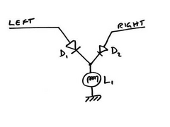 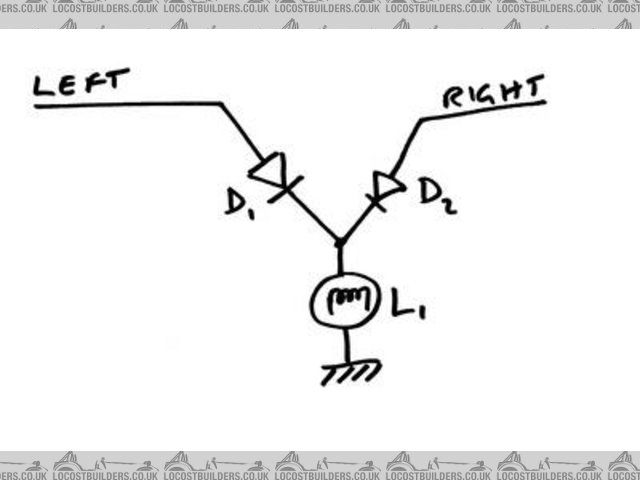
Rescued attachment indicator lamp wiring.jpg
|
|
|
Peteff
|
| posted on 11/4/06 at 10:56 AM |
|
|
Which side will power it when you put the hazards on Take a feed to the bulb from the power into your indicator stalk instead of the outs and you
only have one light.
yours, Pete
I went into the RSPCA office the other day. It was so small you could hardly swing a cat in there.
|
|
|
nick205
|
| posted on 11/4/06 at 01:47 PM |
|
|
lamp is only for indicators, have a separate one for hazard warning.
Not a bad idea though
|
|
|
Dusty
|
| posted on 12/4/06 at 12:00 AM |
|
|
Thats how I did it when I made my loom and it works fine.
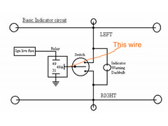
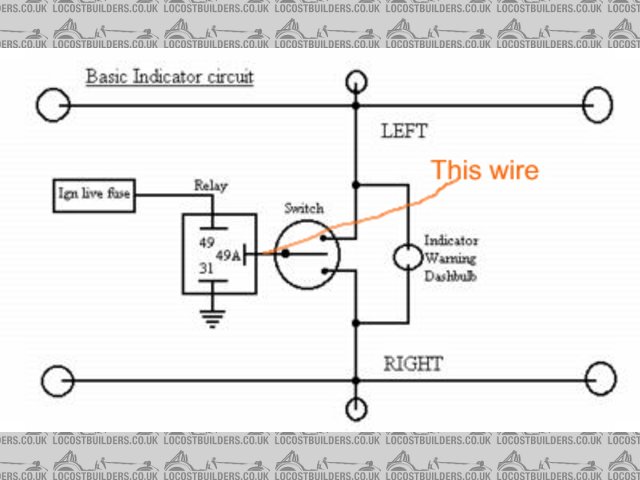
(If you take a feed from before the relay it is an ignition live and the bulb will be on. If from between relay and indicator switch it will activate
the relay and you may get the light on constant, rapid blink or off but current will be flowing all the time the ignition is on.)
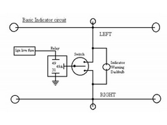 
Rescued attachment dashbulb.jpg
|
|
|
02GF74
|
| posted on 12/4/06 at 01:58 PM |
|
|
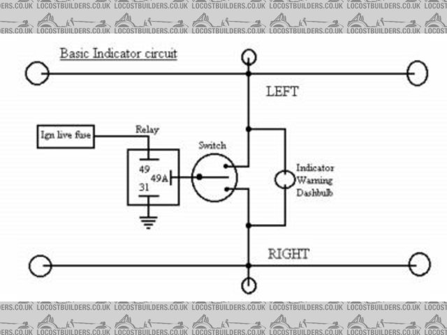
[img]http://www.locostbuilders.co.uk/viewthread.php?action=attachment&tid=42611&pid=354388[/img]
that still doesn;t make sense to me. the bulbs must have 2 connectos, 12 V and 0 V; I only see one common wire. Accroding to that digram, either you
owuld be shorting 12 to gorund or else the indicator bulb has to be grouned via the indicatos in whcih case they would come on.
|
|
|
Peteff
|
| posted on 12/4/06 at 02:43 PM |
|
|
(If you take a feed from before the relay it is an ignition live and the bulb will be on
Yes but nobody suggested that. The one to the switch was the one to go for. If it's in series it shouldn't make any difference to the
relay.
[Edited on 12/4/06 by Peteff]
Rescued attachment dashbulb.jpg
yours, Pete
I went into the RSPCA office the other day. It was so small you could hardly swing a cat in there.
|
|
|
Dusty
|
| posted on 14/4/06 at 12:10 AM |
|
|
Lets say you are indicating right. The indicator bulb recieves power from the right indicator circuit and grounds through the three bulbs in the left
indicator circuit. The amount of current flowing through it is insufficient to light the bulbs in the left indicator circuit it is grounding through.
This is how I wired mine and it does work. 100%. Try it. Definitely lo-cost as no extra bits needed.
If you put the dash bulb in series between the relay and the switch how is it going to flow enough current to light three bulbs down stream of it?
[Edited on 14/4/06 by Dusty]
|
|
|