marc n
|
| posted on 13/7/06 at 09:14 AM |

|
|
Throttle boddies, lamba sensor wiring
HELLO THERE THIS IS KRIS MC.....
.... wiring problems, can any one tell me the answers to these and tell me what they do???
1) the wire/colours for the throttle position sensor on a GSXR 750 K5 throttle boddies ive got a red, black, and a pink(black stripe)
2) the wires/colours/ for a lambda sensor with the 4 wires red/black/white/yellow
any help is appriciated, kris
please email rather than u2u
direct workshop email ( manned 8am till 6pm )
www.mnrltd.co.uk enquireys to :-
chrismnrltd@btinternet.com
|
NOTE:This user is registered as a LocostBuilders trader and may offer commercial services to other users
|
|
|
BKLOCO
|
| posted on 13/7/06 at 09:35 AM |
|
|
You can find the heater wires of the Lambda with a meter. Should be around 10 ohms if I remember correctly. The other two will be signal and signal
ground.
These are very unusual colours for an O2 sensor they are usually two whites for heater. Black signal and grey signal ground.
Experience is what you get when you don't get what you want!!! 
|
|
|
rayward
|
| posted on 13/7/06 at 10:00 AM |
|
|
you can check the TPS with a multimeter, across 2 of the wires you wil have a fixed resistance (doesn;t change when moving the TPS), these are GND and
Vref, the other is the signal.
if it works backwards, just reverse the Vref and GND connections.
hth
Ray
|
|
|
piddy
|
| posted on 13/7/06 at 12:09 PM |
|
|
Take a look here this should sort the lamba sesor wiring one.
linky
[Edited on 13/7/06 by piddy]
|
|
|
piddy
|
| posted on 13/7/06 at 12:13 PM |
|
|
Follow this to find out what wires are what on the TPS.
I used this yesterday to do mine (Looks harder than it is)
MegaSquirt uses the throttle position sensor (TPS) to determine when the engine is at or near full throttle (to shut off feedback from the O2 sensor),
when the engine throttle is opening or closing rapidly (and needing an accel/decel enrichment), and when the engine is flooded and needs to be
cleared. Some people have managed to make their engines function reasonably well without a TPS. This is not recommended with the standard code,
however.
You will need a TPS that is really a potentiometer and not a switch. Many older cars had idle or WOT position switches instead of a real TPS. A real
TPS gives a continuously varying signal with changing throttle. There are two wires on the external wiring schematic that go from MegaSquirt into the
TPS sensor. These two MegaSquirt wires are +5 Vref signal and a sense line. There is a third wire going to ground. Assuming that you have a proper
potentiometer TPS, then +5 Vref goes to one side of the pot, the other side goes to ground and the sensor line is hooked to the wiper.
To hook up your throttle position sensor (TPS), disconnect the TPS, and use a digital multi-meter. Switch it to measure resistance. The resistance
between two of the connections will stay the same when the throttle is moved. Find those two - one will be the +5 Vref and the other a ground. The
third is the sense wire to MegaSquirt. To figure out which wire is the +5 Vref and which is the ground, connect your meter to one of those two
connections and the other to the TPS sense connection.
If you read a high resistance which gets lower as you open the throttle, then disconnected wire is the one which goes to ground, the other one which
had the continuous resistance goes to the +5 Vref from the MegaSquirt, and the remaining wire is the TPS sense wire
|
|
|
stevebubs
|
| posted on 13/7/06 at 12:25 PM |
|
|
In reverse order..
Lambda:
Black Ref. (out)
Yellow Ref. (in)
Red Heater (+)
White Heater (-)
TPS:
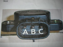 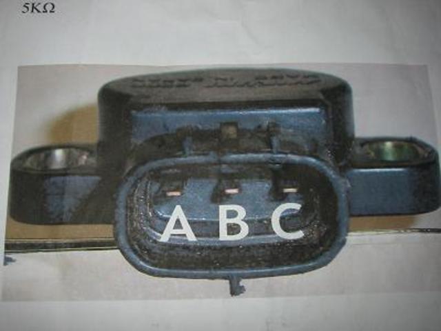
Gsxr750 TPS; A=+5v ; B=Signal ; C=GND
A - +5v Supply (Pin 9)
B - Signal (Pin 8)
C - Earth (Pin 30)
|
|
|
marc n
|
| posted on 13/7/06 at 06:34 PM |
|
|
hello its kris again the throttle position doesnt look like that??
I take it Black is ground and red is +tive???
cheers kirs
please email rather than u2u
direct workshop email ( manned 8am till 6pm )
www.mnrltd.co.uk enquireys to :-
chrismnrltd@btinternet.com
|
NOTE:This user is registered as a LocostBuilders trader and may offer commercial services to other users
|
piddy
|
| posted on 13/7/06 at 07:27 PM |
|
|
Hi Kris.
Mine TPS had Black Earth,Blue live and yellow signal.
|
|
|


.jpg)