mark chandler
|
| posted on 22/1/07 at 09:52 PM |

|
|
Question for Silicon techie types out there
Hi,
I surfed this off the site a few days ago, cannot remember who posted it but the enclosed circuit halves the pulses supplied by the LED switch.
What do I need to do to make the output circuit double/treble the signal or better still make it variable ?
I had a look at the various worksheets and just got more confused.
Do I just link outputs ? or better still can I add a POT so I can vary the clock speed.
Any help in the need of a diagram with show monkey, monkey do text will take me a long way.
Cheers Mark
|
|
|
|
|
MikeRJ
|
| posted on 22/1/07 at 10:43 PM |
|
|
Diving a frequency down by an integer amount is a fairly trivial problem, but doubling the frequency is somewhat more difficult, tripling or providing
a variable ratio is much more difficult.
To double you simply need to fire a monostable on both edges of the input. The probem with this is it gives a fixed pulse width, so duty cycles will
vary as input frequency changes, and this will put an upper limit on the input frequency.
This is a simple circuit using cheap, easily available components:
http://users.otenet.gr/~athsam/frequency_doubler_with_4011.htm
To provide an arbitrary multiplier with an analog solution you need something called a Phase Locked Loop. Unfortunately designing these so they work
robustly over a wide frequency range is not trivial and requires a reasonable knowledge of filter design. http://www.circuitsage.com/pll.html
The alternative, if the frequencies involved are low enough is to use a micro such as a PIC or AVR to perform the multiplication for you: essentially
measure the input period and then generate an output pulse with some fraction of the measured period. This is the way I would go personally.
There is also another possibility, but it won't be very precise. In stead of a Phase Locked loop, you can run an open loop converter. Firstly
convert the incoming frequency to a voltage using a monostable and low pass filter (or a proper F/V converter IC such as LM2917). Scale the output
with an non-inverting amplifier (using pot to control gain) and feed the voltage back into a Voltage/Frequency converter (e.g. LM331). This gives you
infinite adjustment of the input/output frequency ratio, but it will tend to drift (i.e. the frequency ratio is not locked in anyway, but will tend to
vary a bit with temperature etc.). Also getting this to work properly down to very low frequencies may prove challenging.
|
|
|
Bob C
|
| posted on 22/1/07 at 10:58 PM |
|
|
Do you really want to know?
Dividing by an integer is easy - build a wee counter. Multiplying is much trickier - it's possible by a couple of systems:
1) the crap way: f to V converter followed by amplifier, followed by V to f converter. It's an analog system so it has drifts & offsets but
could be made to work
2) proper way - make a PLL (phase locked loop) with a divider in the feedback path - you end up with a frequency multiplier. If you're using a
4046 CMOS PLL chip use the fancy phase sensetive detector (not the XOR gate) as this is wide range & locks better.
3) there will be a PIC (or similar) microprocessor with an internal timer which could measure one frequency & output a multiple of it
Dividing by a number other than an integer - you actually multiply the frequency by between 0 and 1 using a technique called direct digital synthesis
(actually same circuit is used for delta sigma DAC in your CD player....)
Hardware, you'd not use raw logic for any of this, - 1) you could actually use those analog fpgas that zetex have been trying to sell for ages -
the only time I've ever thought of a use for them!) 2) and DDS are asking for FPGA although cheapest & easiest for all is probably a PIC:
but you need to know the techniques in order to write the software.....
I can't believe I wrote all that b/s - 'fraid it's one of those - 'if you have to ask the question the answer won't mean
much' situations... ;^)
Bob
|
|
|
mark chandler
|
| posted on 22/1/07 at 11:14 PM |
|
|
Wow very comprehensive replies, I can see how the 4011 chipset works but the rest is I,m afraid a mystery unless I was to work through some
examples.
Looks like plan A is going to carry on with lots of slots or magnets depending on hall or optical mechnisms to trigger my speedo.
Many Thanks
Mark
[Edited on 22/1/07 by mark chandler]
|
|
|
britishtrident
|
| posted on 23/1/07 at 09:02 AM |
|
|
Jaycar Electronics KC5435
Speedo Corrector MkII Kit £14.95
When you modify your gearbox, diff ratio or change to a large circumference tyre, it may result in an inaccurate speedometer. This kit alters the
speedometer signal up or down from 0% to 99% of the original signal. With this improved model, the input setup selection can be automatically selected
and it also features an LED indicator to show when the input signal is being received. Kit supplied with PCB with overlay and all electronic
components.
> Recommended box UB5 use HB-6015
 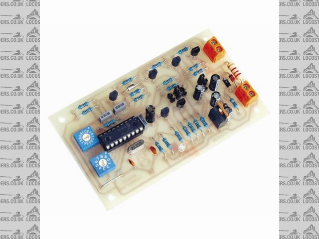
Rescued attachment productLarge_9901.jpg
|
|
|


