MK7
|
| posted on 9/8/03 at 04:20 PM |

|
|
Hi beam switch on 88 (E) sierra
I've read through the various threads but can't find anything that describes my setup...
There's no mention (that I can find) in the Haynes manual for the high beam switch which in my case has 4 wires:
Red (31)
Black (56a)
Green (56b)
Brown/White (56).
Anyone know what the hi-beam switch is called, what it's reference number is and how this should be wired up?
Thanks
|
|
|
|
|
JoelP
|
| posted on 9/8/03 at 04:56 PM |
|
|
i was trying to get my head round my wires the other day, a 1600 f plate sierra.
My trouble was with relays and the dim dip cr4p.
Its possible one of the wires is to do with turning off another circuit. let me check the book, its right here.....
right then... there are 4 wires from the relay because, in order, you have:
1: a black and yellow feed from the ignition relay
2: a brown and yellow from the switch
3+4: both white, a fuse for each (F1 and F2), one for each side of the vehicle.
as for the switch having 4 wires, this was my problem. search for 'dim dip' and it will be part answered. it may be worth replacing a few
parts of the loom, as the dimdip relay is no longer used. something to do with it being illegal to use side light alone in the past, but not anymore.
instead of sidelights, dipped beam was used with a resistor to dim them more.
someone else will hopefully clarify it before i get round to wireing it all wrong myself!
|
|
|
MK7
|
| posted on 9/8/03 at 05:16 PM |
|
|
Thanks for the reply,
I've bought a loom and I've been told I need to wire in relays for main beam and dip. It should be straight forward, take the relevant
feeds from the relevant switches to the new relays then wire the lamps to the high current side of the relay by way of respective fuses.
My problem is that I can't find the hi-beam switch in the Haynes manual so I don't know how it's wired up. I've metered the
switch so I know how it behaves but knowing how this relates to everything else would be useful.
The dimmer switch (Item 36) appears to be close but the numbering is slightly different and the colour code for the wiring is totally different...
Brown (15)
Brown / Yellow (56a)
Brown / White (56b)
Brown / Black (56)
Compared with my switch
Red (31)
Black (56a)
Green (56b)
Brown/White (56)
Anyone see what I'm missing?
|
|
|
theconrodkid
|
| posted on 9/8/03 at 05:26 PM |
|
|
the brown wires are switch to earth,later frauds switched the relay to earth,so you probly got a later switch and an early book,bit confusing but draw
it out on paper first
who cares who wins
pass the pork pies
|
|
|
MK7
|
| posted on 9/8/03 at 05:40 PM |
|
|
So, should I consider that what the book calls the dimmer switch is what I call the high beam switch? i.e. it's on the left of the steering
column with the indicator stalk, push to set high beam, pull to set high beam and dipped headlights?
|
|
|
ChrisW
|
| posted on 9/8/03 at 07:04 PM |
|
|
Sorry to complicate things more but remember there are additional 'issues' to do with the sidelights. On my Ford loom, if you put the
sidelights on without the ignition on the sidelight bulbs come on on their own but if you do it with the ignition on it also puts the main beams in
series across the power so you get them at half brightness. I'm guessing this is the same in the Sierra?
I'm about to wire mine up (later in the week) so I'll do a diagram at the same time if you like?
Chris
My gaff my rules
|
|
|
mad-butcher
|
| posted on 9/8/03 at 07:14 PM |
|
|
whats the part no on your switches
83bg is switched live
67bg is switched earth
my harness came from premier wiring and for an extra £10 he wired the switches up
relays are needed as the ford switchgear is so shite it burns out
tony
|
|
|
bob
|
| posted on 9/8/03 at 08:42 PM |
|
|
Read my no dipped beam thread in this section,petef has put a link to the last time this came up.
My premier loom was all going in fine till i got to the headlights,i had a problem with the dip and main beam.
It turned out to be the earthing on the column switchgear,the flasher stalk and lights stalk are linked by earth.
Unfortunately i had the lights stalk earth wired to the lug on top of the switchgear that was meant to be for the wipers Doh!!
Anyhow the link in "no dipped beam" has some helpfull scribblings
|
|
|
MK7
|
| posted on 10/8/03 at 10:33 AM |
|
|
Tony, the part number on my switch begins 87BG.
I bought the wiring loom from MK, it is manufactured by a company in Warwick called MES, anyone else used one of these?
Chris, any input would be appreciated.
I took a look at Bob's threads (not his clothes) but I think it tackles a different issue, at least I now know what that lug on the top of the
switch does.
I still don't know if I'm looking at the right switch in the Haynes manual, can anyone tell me if this switch is termed the dimmer switch
by Haynes?
Thanks
[Edited on 10/8/03 by MK7]
|
|
|
theconrodkid
|
| posted on 10/8/03 at 11:02 AM |
|
|
diag 2 item 36 looks like panel light dimmer
who cares who wins
pass the pork pies
|
|
|
JoelP
|
| posted on 10/8/03 at 11:53 AM |
|
|
a few observations:
- the light switch recieves power from S1002, direct from the battery and unfused, so side lights will work with the ignition off.
- the dip and main beam headlights earth through the dim dip relay (maybe telling it that they're on) whereas the sidelights have a normal
chassis earth. possibly and maybe probably this relay ensures that the lights only come on with the ignition, this is possible due to the black and
red wire from fuse 17, which is IGN dependant. This relay also has a feed from fuse 1, which is a high beam fuse (LH), so it 'knows' when
the full beam is on as well.
Anyone know what BUSBAR on the diagrams means?
Any why are there two dim dip relays, ii and B?
|
|
|
mad-butcher
|
| posted on 10/8/03 at 12:36 PM |
|
|
i think a busbar is fords way of saying we've lumped and soldered all these wires together
tony
|
|
|
Peteff
|
| posted on 10/8/03 at 01:03 PM |
|
|
S1002 etc.
These are common feeds where wires take power from or earth to, called busbars. There are quite a few of them in the loom. I used the same method in
my loom.With a 100 watt soldering iron you can join loads of wires at once. How old is the switch with the red, black, green and brn/white wires. It
sounds like it may be an early one which didn't use any relays for the lighting circuits. On mine the switches work in conjunction, the
multifunction switch is 102 and the lights/wiper is 94 in my manual. The internal connections diagrams help as they give pin numbers which are also on
the actual switches.
yours, Pete.
yours, Pete
I went into the RSPCA office the other day. It was so small you could hardly swing a cat in there.
|
|
|
mad-butcher
|
| posted on 10/8/03 at 07:01 PM |
|
|
just dug out paperwork from premier
dipswitch for87bg(switched earth)
brown=h/lamp flash,,brown/white=main beam=56a,, brown/yellow=dip beam=56b,, brown/black=supply from light switch=56
lighting switch for 87bg
unfused side light supply=red=30
side/tail supply to fusebox=slate=58
feed to intermitant wiper relay=black/light green=53-2
switched earth return from dipswitch
=brown/black=56
hope that helps
tony
|
|
|
MK7
|
| posted on 10/8/03 at 09:04 PM |
|
|
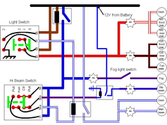
Does this make sense?
I've spent the afternoon mapping out the two switches (light switch and main beam switch) and they behave as shown in the picture. The green
object is the slider that will move left / right to make connection between the relevant red dots.
Internal switch wiring is shown in black, contact numbers are those that appear on my switches (which appear to be different from other peoples).
I've used colours outside the switches which approximate to what I've got, though in reality I'm going to have to modify the MES
harness to accommodate the two relays (shown as black rectangles).
The fusing arrangement may not be ideal but it's what the harness provides so I'm stuck with it.
The operation is that side and tail lights will come on when the light switch is in position 1 or 2.
In position 2 the top relay will operate and so provide 12V to the fog light switch and to terminals 56 and 31 on the hi-beam switch.
With the hi-beam switch in its centre position the 12V on terminal 56 is connected to terminal 56b and onto the 2 lamps (only 1 lamp shown) by way of
a 15A fuse. In this case the switch is carrying the lamp current, is this OK?
When the hi-beam switch is pushed away from the driver this connects the 12V from the top relay to the lower relay (through pins 56 and 56a) which
finds an earth through W on the light switch. This operates the lower relay which connects the 12V to the hi-beam lamp(s) by way of a 15A fuse. In
this case the 12V is no longer switched to the dipped beam lamps.
When the hi-beam switch is pulled towards the driver (i.e. in its spring loaded position), the 12V from the top relay is connected to the dip-beam
lamps by way of pin 56 and 56b and is also used to provide power to the lower relay by way of pin 31 which once again finds an earth through pin W on
the light switch. In this case both the dipped and hi-beams are illuminated, the dipped, as before, passes through the switch whereas the hi-beam is
switched through the lower relay.
Any feedback would be appreciated
[Edited on 10/8/03 by MK7]
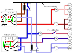 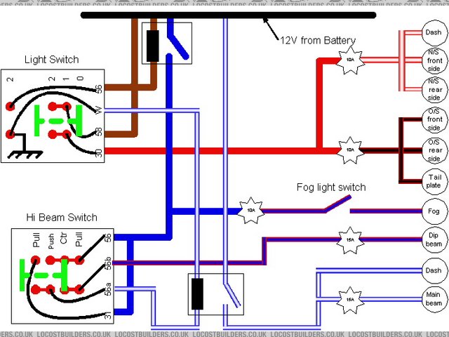
Rescued attachment Lights 2.jpg
|
|
|
theconrodkid
|
| posted on 10/8/03 at 09:21 PM |
|
|
not sure bout dip there,the dip sw should only fire up relays (to earth)as sw is not man enough to carry heavy current,other than that it looks ok
who cares who wins
pass the pork pies
|
|
|
MK7
|
| posted on 10/8/03 at 09:30 PM |
|
|
I couldn't work out how to get the dip beam current to pass through one of the 2 relays, I'm particularly constrained by the light switch
which forces me to use 1 relay to feed the main beam switch. I suppose I could get a 3rd relay.
The total current passing through the switch should only be around 8 1/2 amps, is that a big deal ???
|
|
|
JoelP
|
| posted on 10/8/03 at 09:53 PM |
|
|
that diagram looks good! conrods right on the relays, there are more for the fogs as well. clever how the dips go out on perminant full beam but stay
on for flash full beam. gets rid of some of the shite in the book...
fuses 1 to 7 are all for exterior lights if that helps.
|
|
|
MK7
|
| posted on 10/8/03 at 10:31 PM |
|
|
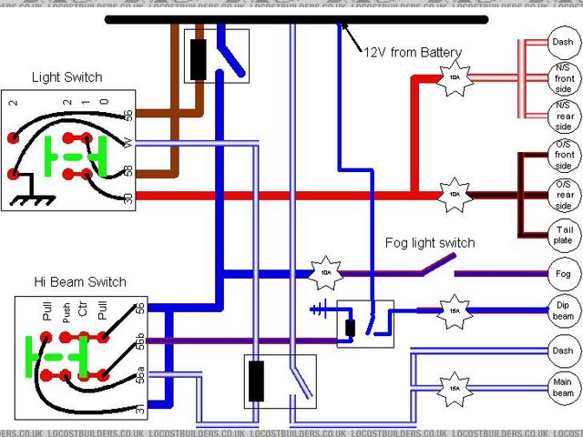
3 relay solution
This is the same as before but in this case the dipped beam current passes through a relay rather than the switch.
I note that the side and tail lights depend on the switch rather than a relay, is everyone happy with this?
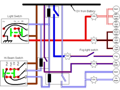 
Rescued attachment Lights 3.jpg
|
|
|
MK7
|
| posted on 10/8/03 at 10:39 PM |
|
|
How many relays?
In addition to the three relays I've shown here, my harness manufacturer (MES) suggests that only 2 other relays are needed, one flasher and one
for the cooling fan.
How many relays are the rest of you using? and if it's more than 5 where are they being used?
|
|
|
JoelP
|
| posted on 11/8/03 at 11:29 AM |
|
|
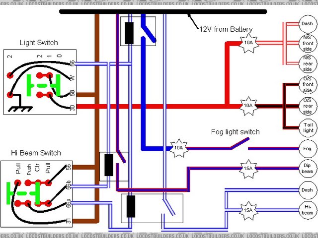
if im wrong, forgive me! i hate to cause a fuss! I think that second diagram has a few errors in it, as several of the relays have lives to both
sides, and maybe wouldn't earth or work....
i think this is how it should be, its your first one modified cos the first was really simple.
Rescued attachment Lights 4 mod.JPG
|
|
|
JoelP
|
| posted on 11/8/03 at 11:32 AM |
|
|
that looks ok i think... the only other thing is a relay for a fog, and maybe add the ignition switch in if you want the lights to go off with the
ign, or not. The first is better cos its really simple, the entire bottom half is activated by one relay...
oops, my mistake! i think your relays are ok in the second one... damn it! still, diagram 1 and 3 are simpler to follow!
the fog lamp is activated by a relay but the full current still goes though the switch, if ya see what i mean?
[Edited on 11/8/03 by JoelP]
|
|
|
theconrodkid
|
| posted on 11/8/03 at 02:44 PM |
|
|
v3 looks ok except you need a live to the dip relay asuming it switches to earth,rear fog dosnt need relay as its only 2 amps
who cares who wins
pass the pork pies
|
|
|
MK7
|
| posted on 11/8/03 at 03:01 PM |
|
|
In V3, the dip relay (indeed all three relays) get their live feed from the brown wire. In the case of the dip relay this enters the hi-beam switch on
pin 56, exits through pin 56b, goes through the relay and finds the switched earth through pin 56 on the light switch and through the switch contact
to pin W.
All three relays find their power and earth through the same process, albeit through different live feed pins on the switches.
|
|
|
JoelP
|
| posted on 11/8/03 at 05:47 PM |
|
|
yeah, i worked it out in the end! soz for the misunderstanding! i've saved the piccies for when i get there!
|
|
|