Cobra289
|
| posted on 11/12/23 at 11:37 AM |

|
|
"LCCT Project"
Hello everybody.
I want to introduce our "LCCT Project"
We are? :
I am "Carlos" from Spain and my son is "Iker" from The Netherlands.
We lives in The Netherlands (close to Rotterdam)
At that period of 2008 I did some 3D work for "Chris Gibbs" for a "Single Seater" possible Publication of Haynes. (Lotus 29
replication)
Single Seater
Therefore some Spanish guys did challenge me to do some 3D work.
So in 2008 I did accept a challenge at the Spanish forum "Forocoches" to design in 3D a Lotus 7 replica with instructions and explanations
in Spanish.
There where some discussions regarding the chassis dimensions and the kind of body to use.
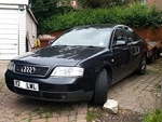
The conclusion where that de dimensions should be close to the Haynes Roadster with adjustments if there where necessary.
That will make possible to use the Haynes Roadster body panels as an option.
Other request was to use the latest production methods, like "Laser-cut" "CNC bending" CNC machining", using of materials
like "Carbon fibers", special aluminum alloys, etc, etc.
But it should have the label "LOCOST" (yeah! right)
I was forced to develop lots of options to have the "LOCOST" stamp.
But in reality the LOCOST therm was forgotten lots of times.
After two weeks I did have the chassis design almost ready for CNC Laser cutting.
I did order ONE set of laser-cut tubes to test here in The Netherlands and see how it goes.
The result was perfect because we fulfill to the request of consistency and repeatability.
So we initiate at the Spanish Forum a "Group Buy" and after a while there where order 35 chassis package.
OK let me explain what means LCCT
L = Low
C = Cost
CT = 7 (In Spanish if you read fast the letters "CT" sound as a 7)
CHASSIS DATA:
- Has originally 111 square tubes with a total length of 50 m
- 61 plates cut and bend to suit. (all most all have a 3 mm thickness)
- Weight of 55 kg.
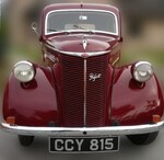
After a while I did design several type of bodies and we did choose for the so call "Flat Nosed" type.
In the next post I will extend more in details about the developments.
Off-course we where hit by the "Financial Crisis" and all the other crisis that we have had since.
But first some pictures of the 3d concept and the real build with the results so far.
The LOGO of the project.

Selected Body style.

First impression of the progress.

OK this was my first post of our project, more will follow.
Kind Regards,
Carlos
[Edited on 12/11/2023 by Cobra289]
[Edited on 12/11/2023 by Cobra289]
[Edited on 12/11/2023 by Cobra289]
[Edited on 12/11/2023 by Cobra289]
[Edited on 12/11/2023 by Cobra289]
|
|
|
|
|
Cobra289
|
| posted on 11/12/23 at 12:27 PM |
|
|
Other pictures.


The full body has been made from Carbon fibers and epoxy resin.
We have use the method of Vacuum Infusion of the resin.
With that we manage to get a body thickness of 1,3 to 1,5 mm with a great strength.
kind regards,
Carlos
[Edited on 12/11/2023 by Cobra289]
|
|
|
Cobra289
|
| posted on 11/12/23 at 01:29 PM |
|
|
More pictures from the body fabrication.
At the end we manage with 5x Spanish persons to invest and buy CNC machined molds according to my 3D model.
The agreement was to build a series of 5x bodies.
The molds where fabricated in Spain and transported to The Netherlands.
We initially we use MDF material for the molds machined with a "Kuca Robot" but the Spanish manufacturer did stop the production after the
fabrication of several peaces.
We have had a lot of work to prepare correctly the MDF molds, so my advise is "Don't use MDF if you can"
After a while we found a Barcelona based company, that fabricates molds for VW & Seat, so I plan a visit during my holidays and we direct ordered
the fabrication of high density PU molds.
Materials from a German company call Ebalta and we have use the type "Ebaboard 700"
Ebaboard 700
The disadvantage is the weight 700 Kg/m³ and bring it to the attic was a challenge.
My son Iker and my self were involved with the fabrication of each carbon piece and we did that at the attic at home.
It was a mentally consuming activity, because it was not only necessary to construct one peace but some times 10x peaces.
There are other persons (in Spain) that use the LCCT chassis in combination of the Haynes Roadster body.


This is the smallest lamp that I have found, is NOT the one that you think!


Up to the next post.
|
|
|
Cobra289
|
| posted on 11/12/23 at 02:06 PM |
|
|
The design of the pedals.


Kind regards,
Carlos
|
|
|
JoelP
|
| posted on 11/12/23 at 07:28 PM |
|
|
Some fantastic work there. I love the 3d with the roof on.
|
|
|
ReMan
|
| posted on 11/12/23 at 10:20 PM |
|
|
Good work, some nice touches you are working on. As said a roof option is always good, a modern screen and nice bodywork styling touches
www.plusnine.co.uk
|
|
|
Cobra289
|
| posted on 11/12/23 at 10:33 PM |
|
|
quote:
Originally posted by JoelP
Some fantastic work there. I love the 3d with the roof on.
Hi Joel,
It is good that you mention the roof or hard-top.
For us this would be the second face of the project.
First we want to put the LCCT on the road and later we can concentrate our efforts with the hard-top.
We have choose a different method for the fabrication due that the CNC carving the Ebaboard would be very costly.
So we have already CNC machined the parts from hard PU foam that would be form our buck and from there we should fabricate our molds.
3D design of the roof (Hard-top) did have some complexity to get the right proportions and respect the space management.
In such small cars it difficult to get the right proportions and if you don't follow the lines it becomes a "wart" instead of a
harmonious shape.
Kind regards,
Carlos
|
|
|
Cobra289
|
| posted on 11/12/23 at 11:02 PM |
|
|
quote:
Originally posted by ReMan
Good work, some nice touches you are working on. As said a roof option is always good, a modern screen and nice bodywork styling touches
I am happy that you like the roof. Like I just say, we have the pieces to fabricate the buck but it will take a while before I can post a picture of
the real roof.
Have a different windscreen was a forced item of the design of the body, you know I need to follow the lines.
I manage to design a conical shape with only one curvature, that it will easy to fabricate.
At the end we made our self a steel mold for the windscreen manufacturer from Spain that casualty has also a Lotus Seven replica.
The washer and wiper system uses the Peugeot 205/309 wiper motor support but the arms and all the other components where made by the company DOGA from
Barcelona.
I did all the required simulations of movements in 3D design according their requirements and they came with the advise for the arms and brushes for a
very cheap price.
It will work at two speeds and we forget for the moment the interval option.
SIMULATION VIDEO (6 Mb)
Kind regards,
Carlos
|
|
|
Mr Whippy
|
| posted on 12/12/23 at 07:29 AM |
|
|
It's all very nice, although I do wish the fuel tank was not still as vulnerable as something from the 1930's
|
|
|
Cobra289
|
| posted on 12/12/23 at 09:25 AM |
|
|
quote:
Originally posted by Mr Whippy
It's all very nice, although I do wish the fuel tank was not still as vulnerable as something from the 1930's
I understand your concerns.
I know that I can't never convince you or others, because this safety is a difficult matter.
Liquid fuel is difficult ignite, you need a reasonable concentration of vapors to have a dangerous situation.
Impact is not a reason for fire.
There are several improvements compared to the 1930's design.
We don't have a bottom take-offs a typical source of problems and leaks.
Venting systems, charcoal evaporation canister, reinforcing partitions walls, viton gaskets, etc, etc.
The wiring looms and connectors are one of the origin of fires and there are not related to the fuel.
Jus plastics and fast fire propagation of bad materials used, like underrated wiring. etc.
NON sealed electrical connections.
Most of the fires are originated at the engine bay, leaking hoses, broken or bad connections.
Other area of concern is area close to the wheels.
I put some pictures of the design so that you and others can see how has been made.


Kind regards,
Carlos
|
|
|
Cobra289
|
| posted on 12/12/23 at 10:00 AM |
|
|
The LCCT Suspension and the geometry
Hello ,
The LCCT Suspension and the geometry.
Here is my opinion and my setup. (Nothing worth, just that)
Design a suspension package is something that need to have some attention and dedication.
First we have defined the wide of the car (front and rear tracks) and the wheelbase of the car.
The track at the rear depends of the components that we will use (Sierra differential 7" etc.)
If we use the "Golden Ratio" to define the wheelbase with a average track of 1443 mm we should select a wheelbase of 2335 mm.
But I prefer to have a longer wheelbase to get less nervous character of the car.
Then we came to the selection of the tire diameter.
We did select a tire diameter of +/- 600 mm because you can get good tires with 15" wheels and also with 16" wheels with the same diameter.
(Yes I know that the unsprung weight should be low)
Once we where happy with this numbers we did start with the concept "LCCT Geometry Design"
So the design parameters of the LCCT are:
Wheelbase = 3472 mm
Front track = 1438 mm
Rear track = 1449 mm
IC front = +57 mm
RC front = +27 mm
KPI = +7°
Scrub Radius = 35 mm
Camber = -2°
Caster = +6°
Wheel size = 15" or 16"
Tire size = 195-55 R15 or 195-50 R16
Front bump 60 mm
Front drop 60 mm
Oh! man we can have a lot of theories and practices, even F1 design designers use to have stupid numbers.
The thing here is to be happy with what you do and to have enough adjustability to get it functional.
The main goal here is to get CERO Toe-In or Toe-Out
I explain:
Every suspension we have three arms that are:
- Upper arm
- Lower arm
- The steering arm.
Then it is about finding two compatible mechanisms that accept the movements of these three arms.
(A door with three hinges has these requirements, the center hinge doesn't push or pull, just only rotate)
With that in mind I did define the arms lengths, the steering rack wide and height position.
After that I did several 3D line simulations to control the toe-in and we where very please with the results.
After this process I found that use of the Ford Sierra Upright will be difficult for my setup.
So therefore I decided to design my own upright with the dimension that suit our definition.
The first option was fabricate one with laser-cut plates and bend to suit, this is the cheap option (Low cost)
The second option is to machine with CNC and from Aluminum Alloy AL7075 T6.
The design of the upright steering arm need also some attention to get a desired Akkerman effect.
With that completed I have defined the front Shock Absorber length by defining the bump of max 60 mm and drop of 60 mm
This is for now.
Kind regards,
Carlos
|
|
|
Mr Whippy
|
| posted on 12/12/23 at 10:06 AM |
|
|
quote:
Originally posted by Cobra289
quote:
Originally posted by Mr Whippy
It's all very nice, although I do wish the fuel tank was not still as vulnerable as something from the 1930's
I understand your concerns.
I know that I can't never convince you or others, because this safety is a difficult matter.
Liquid fuel is difficult ignite, you need a reasonable concentration of vapors to have a dangerous situation.
Impact is not a reason for fire.
Carlos
Like I said all your 3D models and prototypes are very shiny and impressive. But cars bursting into flames after rear shunts is very real and not to
be dismissed easily. Personally I'd be happy to loose a small bit of that perfect weight distribution, just to have the tank located 10 inches
higher above the diff. Everything behind the diff would be much better as a block of high density foam.
youtube Pinto
[Edited on 12/12/23 by Mr Whippy]
|
|
|
ReMan
|
| posted on 12/12/23 at 08:28 PM |
|
|
quote:
Originally posted by Cobra289
Hello ,
The LCCT Suspension and the geometry.
Here is my opinion and my setup. (Nothing worth, just that)
Design a suspension package is something that need to have some attention and dedication.
First we have defined the wide of the car (front and rear tracks) and the wheelbase of the car.
The track at the rear depends of the components that we will use (Sierra differential 7" etc.)
If we use the "Golden Ratio" to define the wheelbase with a average track of 1443 mm we should select a wheelbase of 2335 mm.
But I prefer to have a longer wheelbase to get less nervous character of the car.
Then we came to the selection of the tire diameter.
We did select a tire diameter of +/- 600 mm because you can get good tires with 15" wheels and also with 16" wheels with the same diameter.
(Yes I know that the unsprung weight should be low)
Once we where happy with this numbers we did start with the concept "LCCT Geometry Design"
So the design parameters of the LCCT are:
Wheelbase = 3472 mm
Front track = 1438 mm
Rear track = 1449 mm
IC front = +57 mm
RC front = +27 mm
KPI = +7°
Scrub Radius = 35 mm
Camber = -2°
Caster = +6°
Wheel size = 15" or 16"
Tire size = 195-55 R15 or 195-50 R16
Front bump 60 mm
Front drop 60 mm
Oh! man we can have a lot of theories and practices, even F1 design designers use to have stupid numbers.
The thing here is to be happy with what you do and to have enough adjustability to get it functional.
The main goal here is to get CERO Toe-In or Toe-Out
I explain:
Every suspension we have three arms that are:
- Upper arm
- Lower arm
- The steering arm.
Then it is about finding two compatible mechanisms that accept the movements of these three arms.
(A door with three hinges has these requirements, the center hinge doesn't push or pull, just only rotate)
With that in mind I did define the arms lengths, the steering rack wide and height position.
After that I did several 3D line simulations to control the toe-in and we where very please with the results.
After this process I found that use of the Ford Sierra Upright will be difficult for my setup.
So therefore I decided to design my own upright with the dimension that suit our definition.
The first option was fabricate one with laser-cut plates and bend to suit, this is the cheap option (Low cost)
The second option is to machine with CNC and from Aluminum Alloy AL7075 T6.
The design of the upright steering arm need also some attention to get a desired Akkerman effect.
With that completed I have defined the front Shock Absorber length by defining the bump of max 60 mm and drop of 60 mm
This is for now.
Kind regards,
Carlos
You definitely don't want to design in old legacy parts like Sierra hubs and rear axel.
Also many would frown on 16" wheels as too big. Entirely your choice of course, but 13" are definitely favoured for roadholding, although
15" is often preferred for aesthetics (myself included)
www.plusnine.co.uk
|
|
|
Cobra289
|
| posted on 15/12/23 at 11:33 AM |
|
|
quote:
Originally posted by ReMan
You definitely don't want to design in old legacy parts like Sierra hubs and rear axel.
Also many would frown on 16" wheels as too big. Entirely your choice of course, but 13" are definitely favoured for roadholding, although
15" is often preferred for aesthetics (myself included)
OK perhaps is the 16"wheels are a bit to much.
I am a freak of brakes, at the track (Zamdvoort with to much turns) you need to have good brakes to take advantage at the corners.
Small wheels (in my opinion) only have the advantage of small reduction of the "Unsprung weight"
For me it is not a problem the aesthetics because if you maintain the tire diameter the looks will be equivalent.
Also if you maintain the tire size what you reduce in weight at the wheels you put some extra at the tires.
Off course the weight of the wheels are very important to reduce the unsprung weight. I use special German wheels from Autec (Wizard type) very
reduced weight.
But there are more components that should be reduce the weight if we can afford.
The upright, the hub, the hub fixing bolts, the wheel bolts (or nuts), part of the shock absorber, support of the wheel wing, reduced weigh of the
brake disk, caliper, wheel wing and other items that are involved in the Unsprung Weight.
Have you done everything to reduce the weight of all these components? that is the important question.
I can tell you that "YES" I have done a lot to reduce the weight, some times it cost a fortune but all the bolts are from
"Titanium"
The wheel wings are also light, self made from carbon fibers with 1,3 till 1,5 mm thickness with reinforced edges.
The upright was made from Aluminum alloy.
The wheel hub is special design and not the standard used type, with integrated sealed bearings per-adjusted play.
Here some pictures.


Reinforced edge of the wheel wing. I use a hem rope to get fibers at the corner.


Kind regards,
Carlos
|
|
|
Cobra289
|
| posted on 19/2/24 at 09:16 AM |
|
|
Here are some videos.
You can see the total rear body part after gluing all the 7x pieces.
It is very light and at the same time super strong.
REAR BODY (39Mb)
The other video shows our trunk opening.
TRUNK (33Mb)
The next video was made to show how strong are the body parts.
We have had a problems with the first nosecone, the mold was not treated correctly with the release agent so we did have a part were the surface was
damage.
So I used to make a video that shows how strong is the part.
NOSECONE (120Mb)
Kind regards,
|
|
|
Cobra289
|
| posted on 19/2/24 at 09:27 AM |
|
|
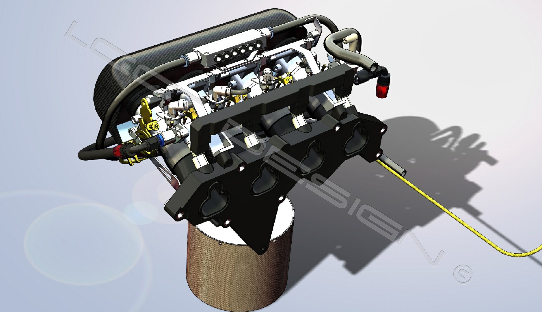
The last period we finally we did start the LCCT for the first time.
The exhaust was not installed, only the manifold.
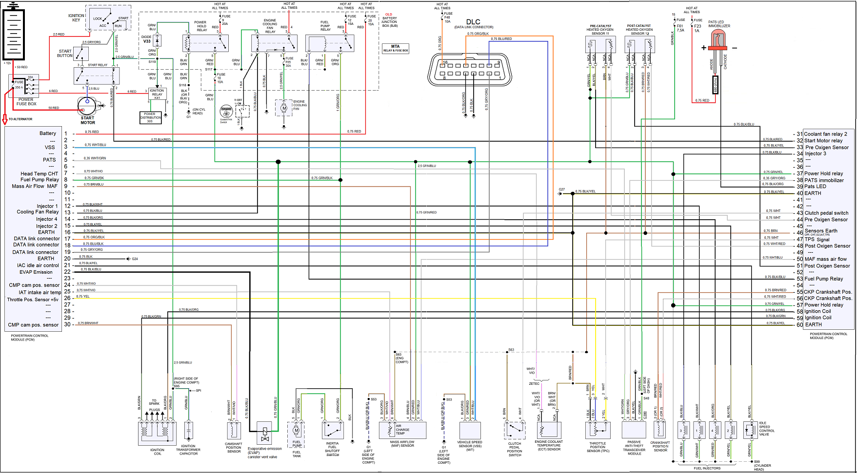
The PCM (ECU) and wiring is a version of the original Focus MK1 but striped to the minimum.
We use the PCM with the code TEEM (from +/- 2003)
FRIST START (1,7 Mb)
OIL PRESSURE (80 PSI) (3,5Mb)
Here is the wiring diagram that we have use.
Kind regards,
|
|
|
Cobra289
|
| posted on 19/2/24 at 09:49 AM |
|
|
The Dashboard was made from a light material.
In our case we use PVC foam plates of 5 mm thickness.
I did use a heater gun to bend and shape the dashboard.
Very easy to work with it.
The reinforcing strips were glued first with PVC glue and after several seconds they hold the form.
After that I did use Epoxy glue (construction glue)
The edges where glued.
We did use veneer to cover the exposed area.
This surface was treated with several coats of clear epoxy.
It is a time consuming but very rewarding with the results.


[Edited on 2/19/2024 by Cobra289]
|
|
|