
SolidWorks Help please!
Steve Hignett - 4/1/11 at 05:37 PM
Hi All,
I really should learn it I know, but I'm trying to draw the two items from my crappy sketch below.
I'm planning on making a petty strut brace using carbon fibre tube and machined titanium ends, and wanted to draw it first...
The upper one is relatively straight forward (well, not easy enough for me to do it!), it just wants a saddle type bracket going round the Rear Diag.
brace standard location, but the lower one is to have a single sided leg coming off to use a caphead bolt going through to the Caterham's top
rail (standard fitment point) hence the funny angle.
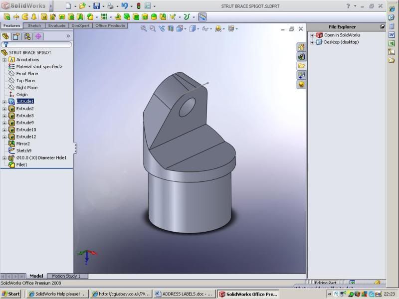
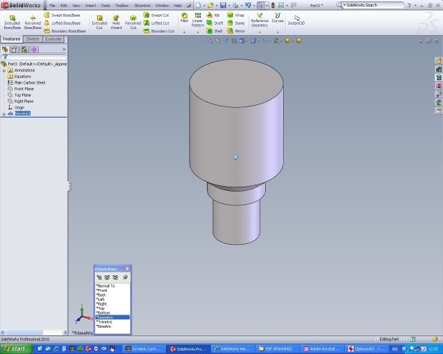
Embarrasingly enough, all I've managed to draw (after 15 mins looking!) is the hollow cylinder base that would go through into either end of the
tube, and immediately got stuck doing the hard stuff!!!
Here's a snap of what I've got already;

Here's my dodgy sketch of what I need to learn to draw; (Lower on left, Upper on right)

And this is what it'll be going on...

Thanks in advance for all suggestions and advice,
Steve
mads - 4/1/11 at 05:48 PM
Steve,
Has Alex seen this yet? If not, he will soil his pants with the amount of CF in that photo alone!! 
balidey - 4/1/11 at 06:00 PM
Not at work now, but will try and explain how I would do it.
1st draw a vertical centre line.
Then draw half the profile to the largest diameter (ie you model how you will make it, so largest bar stock turned down).
Then rotate a solid, so you have a round part.
Then a sketch on the front plane and sketch what you want removing, then extrude a cut forwards and backwards.
Then you should have the part and you can then add holes onto the newly cut faces.
If i was at work I could have done it in a couple of mins and done screen grabs to help explain. If you haven't got it sorted by tomorrow AM then
I'll do that for you.
balidey - 4/1/11 at 06:09 PM
As an aside, is there any need for a brace?
I know it will look pretty and be in light material, but have these type cars actually got a need for bracing. Surely the chassis itself does a better
job than this add on part?
And this is not a 'dig', just curious to find out why you want to do it?
Surely if you want to add CF, then perhaps a cup holder?
orton1966 - 4/1/11 at 06:14 PM
There is often more than one way to do these things and it often doesn’t matter how you get at the result until you want to make changes but on such a
simple shape it doesn’t really matter. I’m no expert and stumble my way though but I do see a couple of ways to do the models you want:
The crudest and easiest is form an extrude boss/base (on top of what you have already drawn) in one plane (choose the mid plane option) to give a
block with the correct outside profile, next chose a plane or face, at 90 degrees to the first, so if you did the block working on the right plane, go
to the front plane. Here do an extruded cut to take the part of the block you don’t need away. Finish by filleting any edges that need it.
Another way is to do the flanges by offsetting from a plane for the extrude or if the shape was harder create a new plane.
Just have a bit of a play but with relatively simple shapes don’t get hung up on doing them a particular way
balidey - 4/1/11 at 06:19 PM
I do agree with most of what orton1966 said, there are always more then 1 way of doing things in SW.
But from vast experience using it, I find the best approach is always to model it like you would make it.
And in this case it would almost certainly be turned down to the maximum profile shape and then a mill to cut front to back to add the shaping you
want, then any cross drilled holes added.
ie treat every operation in the model as a 'real life' operation.
Personally I think extruding shapes onto that base would not give the best results in this case.
FASTdan - 4/1/11 at 07:25 PM
I can see your problem right away.......solid works lol. get inventor, proper software I tell thee.
No seriously if I get chance and your not sorted ill have a look shortly.
orton1966 - 4/1/11 at 07:32 PM
quote:
Originally posted by balidey
I find the best approach is always to model it like you would make it.
And in this case it would almost certainly be turned down to the maximum profile shape and then a mill to cut front to back to add the shaping you
want, then any cross drilled holes added.
ie treat every operation in the model as a 'real life' operation.
Agreed
indykid - 4/1/11 at 09:20 PM
quote:
Originally posted by orton1966
quote:
Originally posted by balidey
I find the best approach is always to model it like you would make it.
And in this case it would almost certainly be turned down to the maximum profile shape and then a mill to cut front to back to add the shaping you
want, then any cross drilled holes added.
ie treat every operation in the model as a 'real life' operation.
Agreed
Thirded
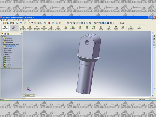
I had a go for you, took about 20 minutes but that was more second guessing dimensions and using a mouse on the sofa next to my laptop

- extrude the bar stock on the top plane
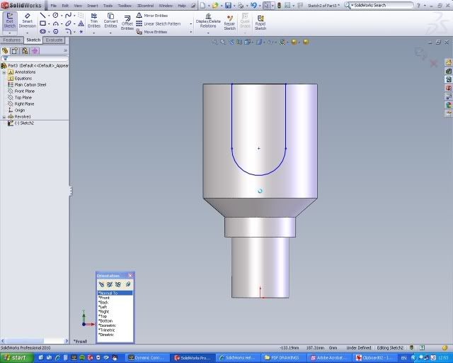
- sketch the revolved cut on one of the vertical planes, revolve the sketch (select view>temporary axes to get the axis of revolution)
- sketch the revolved cut for the internal bore, revolve as above
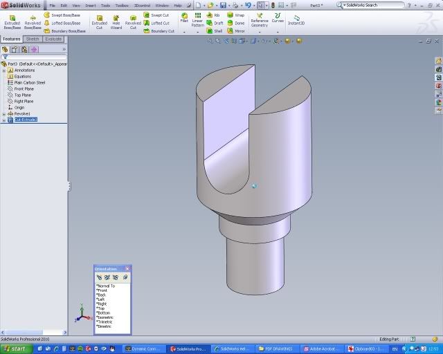
- select right plane and sketch the shape of the lug, make a 2 direction extruded cut through all
- select the front plane, sketch the shape of the slot and the faces of the clevis, extruded cut as above
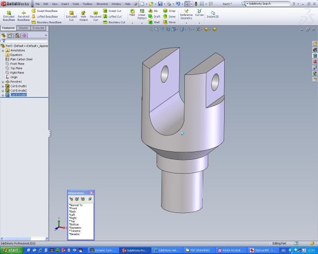
- select hole wizard, make a clearance hole to suit the clevis bolt. (i had to make the centre of the hole and the o.d of the clevis lug concentric
because it didn't like it being aligned with the temporary axis, but you can position yours to suit)
- press space, select isometric, check it looks right, add any fillets and chamfers
- done
[Edited on 4/1/11 by indykid]
FASTdan - 4/1/11 at 10:27 PM
I may have misunderstood, thought you wanted the angled one drawing. Anyway, if you did heres my interpretation (with guessed dimensions)
Just learning SW as im an IV user day to day.
[Edited on 4/1/11 by FASTdan]
Steve Hignett - 5/1/11 at 08:38 AM
Thanks for all replies so far!!!
Mads;- I daren't talk Alex into anymore CF as he'll prob beat me about the head if I do - He know's where I am and what I do 
Baliday;- Need for the brace? Well I'd say it was 25% me wanting to do it, 25% for it being there to look amazing, and 50% need for it. The car
will only weigh 440kg ish, but it'll have between 550 and 600 hp so it will be a pretty powerful car and in my humble opinion, benefit from some
stiffening in the most open area of the car...
Fastdan;- you're (sort of) not wrong, I need help on both of them, but I did say above that I'd find the single sided one more difficult!
Baliday/Orton/IKid/FDan;- Thanks for having a crack! I wish I was little more PCProgramme-minded!!! Most of the time, even if I do learn stuff I need
reminding how to do it. I guess it doesn't help only having an QI of 69
I will have a go now, and report back on my attempts!!! Main problem is that I use the programme so infrequently that I don't know where stuff
is!
Anyway, thanks for advice so far, I will try and follow your brief guides...
Steve
ps as for sizes, I don't have any myself yet as I haven't ordered the tube, was going to have one made just for me with a really fat weave,
like a 4x4 twill  but I haven't told the person who's paying any of this yet
[Edited on 5/1/11 by Steve Hignett]
Steve Hignett - 5/1/11 at 11:27 AM
Hey guys,
My little boy is v poorly at the moment so I can't get on the pc as Its In the "nursery/office/2nd bedroom"
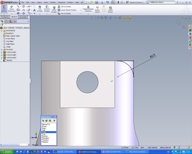
But, I must be doing something stupidly wrong as I started to do as per some suggestions above:
Went to.right plane, drew a rectangle, extruded it 60mm mid plane so it was central to the lower twin barrels cylinder. BUT when I then went to
extrude the centre out of It In eithrr right or centre plane it greyed out all the options an highlighted Exit Sketch
???
Thanks again...
[Edited on 5/1/11 by Steve Hignett]
MikeCapon - 5/1/11 at 11:57 AM
Because you need to have exited the sketch before you can use it to extrude?
balidey - 5/1/11 at 12:10 PM
Sounds like you have gone to edit an existing sketch of an existing feature, ie instead of a new sketch to then create a new extrude you may be in
another one, so it needs you to exit the sketch.
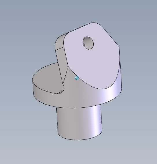
Also I have had a quick stab at the angled item. Its a very odd shape when you start to model it. To give you a nice shape to the top lug you need to
do a secondary mill operation on the top. Couple of sketches attached.

balidey - 5/1/11 at 12:21 PM
Also, rather than machining the twin leg item, you do realise its actually just a clevis and you will be able to get one off the shelf? Maybe not in
Ti but TBH a steel or even larger alloy item will not weigh any more.
And instead of the angled item I would look into whether another clevis and a rose joint would give you the angle you need, much better than machining
that horrible shape and wasting all that Ti
Steve Hignett - 5/1/11 at 12:41 PM
Mike:- I thought that at first so I deleted and started again to get the same result! It's obviously just me doing something wrong, but I am
totally clueless re SW (and all programmes TBH!)
Balidey:- Thanks again for the sketches...
I've just had a crack at it and there some very obvious things I'm not able to conceive in SW...
I've just progressed to drawing a cone on top, then a filleted cuboid on top of that with a hole through it - I haven't tried to extrude the
centre out of that yet, as that's when I just noticed your replies!
It's not pretty though! It doesn't meet the existing disc and I don't know how to make it meet either! I'll include a screenshot,
but not much point as it is SO wrong!
With re. the necessity of it, no it isn't worth doing it in Titanium. Ali would be fine, one off the shelf would be fine too, assuming one fit
the rear diag. and the CF tube...
BUT, I want to try and learn SW a little at a time if I can, and that was one reason, the other is that I can prob get the material and machining done
for free if I really tried as one of our customers is a machine shop for the F1 and Aerospace industry and we've worked hard to satisfy an order
that he couldn't fulfill.
With re the lower, my first thought was indeed a rosejoint (it would also allow me a bit of discrepancy in the length of the tube, should anything be
out a tiny amount). But I think the angle is going to be too extreme. Will have to check though - does anyone have a link to any RJ articulation
tables per RJ size?
Steve Hignett - 5/1/11 at 12:46 PM
balidey - 5/1/11 at 12:50 PM
ok, I see what you mean about it not meeting now.
What you have done on the lower part is a turned item, lets say for arguments sake its 50mm dia.
You then extruded a block off the top of that, which is smaller than the outer dia of 50mm, so it looks like its been added, where as to make this you
will start with a bigger lump and remove material. Like I said, model it as you make it. Will try and explain quickly in a minute with some sketches.
balidey - 5/1/11 at 12:57 PM
this is how i would do it...

Steve Hignett - 5/1/11 at 01:08 PM
U2U sented!!
Liam - 5/1/11 at 01:15 PM
For learning solidworks have you gone through the included tutorials? They're pretty good and I'd have thought that if you'd gone
through those you would find this fairly easy.
Also, just for my own curiosity's sake I'm wondering if you could indicate where this brace is going on a chassis pic as I'm struggling
to tell from your description. I'm wondering if it's really going to do anything structurally, especially with one end being that angled
tab.
Steve Hignett - 5/1/11 at 01:20 PM
I have tried the tutorials (a long time ago) but I fear you are underestimating my stupidity!!!
When I learn something, I only just grasp it, yet when I go back to it 12 months later, it's forgotten...
Programmes and myself have never ever got on....................
I can't modify the above photo well enough, so here's the first car I built with a very similar one fitted...
.JPG)
.JPG)
balidey - 5/1/11 at 01:24 PM
You don't like passengers do you?
I thought this was a suspension brace. Now it makes sense. I'll give you a call shortly.
Steve Hignett - 5/1/11 at 01:35 PM
Passengers... Passengers???
To be fair this latest one is in a pretty high spec car and I think it'll prob be needed!!!
Waiting by the phone
Steve Hignett - 5/1/11 at 02:12 PM

Steve Hignett - 5/1/11 at 02:16 PM
Mucho Thanks to Balidey - one phone call, where he spent most of it rightly laughing at my (lack of) knowledge and a few pointers has got me on the
track...
There are a few things that I couldn't still figure out.
1. I couldn't fillet the top to make the side profile more rounded and pleasing to look at
2. I don't know how to mke the transition from the cone (in middle of part) to the upper part more attractive
Actually - I have thought of a simple way - make the upper bit the right size to start with
Thanks again to all, especially Balidey...
[Edited on 5/1/11 by Steve Hignett]
balidey - 5/1/11 at 02:27 PM
No problem. Good to hear about the project.
To add a fillet on top is awkward as its a turned item. So SW will struggle to put it on the model as its a point not an edge.
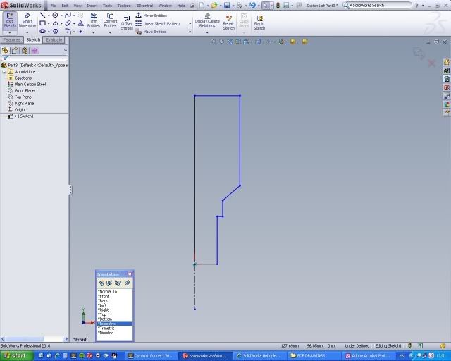
One way is to do a cut through the side. I often have to do this little 'cheat'. Only did one side to show you, and cut through all in both
directions.
To do this shape I draw the two lines first then draw an arc and mate it tangentially, that way its smooth to the edges.

[Edited on 5/1/11 by balidey]
Liam - 5/1/11 at 02:40 PM
Oooooh I see - one of those! When you said strut brace I thought you meant, well, a strut brace  . Yeah I hear those are useful tubes - though I
thought more to help prevent the role bar folding up in an accident rather than adding anything to the stiffness of the chassis, certainly torsional
stiffness anyway. So there's really no way you can weld suitable bosses/clevises to the chassis and just make a bar with rose joints at the
ends?
. Yeah I hear those are useful tubes - though I
thought more to help prevent the role bar folding up in an accident rather than adding anything to the stiffness of the chassis, certainly torsional
stiffness anyway. So there's really no way you can weld suitable bosses/clevises to the chassis and just make a bar with rose joints at the
ends?
One other thought that just occured to me - if you do have an accident, and that tube does take a big load, and being CF splinters into nice sharp
shards, you might not want to be sitting so close to it!
/Scaremongering off
Steve Hignett - 5/1/11 at 02:44 PM
This car is going to end up costing between Ł85k and Ł100k. If I have a big accident in it on it's two shakedown trackdays at Oulton, before
I've given it to the owner, then the least of my worries will be CF splinters..........
I've got 2 in my right palm at the moment and can't be arsed getting them out
Here's my second attempt...

Liam - 5/1/11 at 03:00 PM
Nice - but the prettier it looks the less likely your machining buddies are going to want to make it for free .
Hmmm - I was thinking more like biiig CF broken tube-ends going through your brain, but maybe I'm being a little melodramatic now. Ah well - as
long as you drive safely on the shakedown days, never mind the owner!
Out of interest, what is the monster 550-600BHP motor going into it?
Steve Hignett - 5/1/11 at 03:31 PM
I know what you mean re the machining cost/favour!
I'm not 100% convinced that the favours we've done for him/them are equal, but the worst he cab do is say no!
The CF would never shatter In that manner near me, so I think you may be reading a little too deep on this one!
The engine Is being built still although it should have been completed end of Nov. 
It will be the RS Performance V6 (same guy as caterham levante V8). This will be a 2.3l V6 with a supercharger, weigh about 90 kilos and as above be
about 550-600 bhp. The box is a Sadev 6 speed sequential and I've ordered the geartronics paddle change...
Search YouTube for RS v6 and RS levante if you want a taster, theres a vid of the v6 on a dyno and one with It in his own exige type car...
[Edited on 5/1/11 by Steve Hignett]
Steve Hignett - 5/1/11 at 04:49 PM

Steve Hignett - 5/1/11 at 08:14 PM
quote:
Originally posted by Liam
Oooooh I see - one of those! When you said strut brace I thought you meant, well, a strut brace
Sorry Liam, I called it that In my OP as I actually thought they are called petty strut braces... my bad!
I used to call the first one I fitted a "forward diagonal" but was corrected and told it was called a "petty strut brace"...
Ah well, live and learn...