tegwin
|
| posted on 22/11/11 at 09:38 PM |

|
|
OT: LED Dimming
Any clever electrical folks here tonight?
If I have the following circuit supplying a constant current to an array of LEDs:
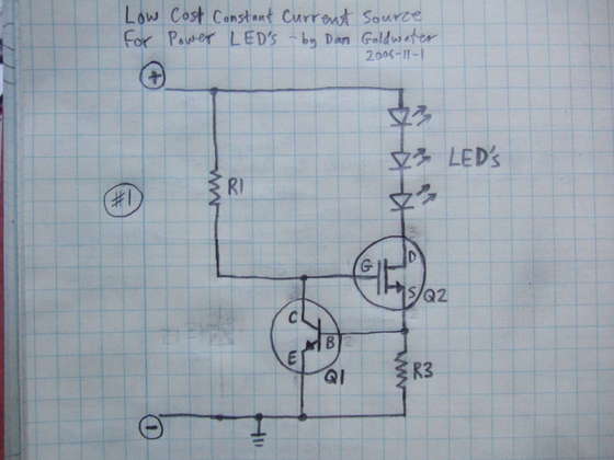
What change to the above would I need to make if I wanted to control the brightness of the LEDs using a PWM signal (say from a simple 555 oscilator
circuit).
I cant quite get my head around it.
Schematic is from here:
http://electronics-diy.com/power-led-driver-circuit.php
------------------------------------------------------------------------------------------------------------------------
Would the last person who leaves the country please switch off the lights and close the door!
www.verticalhorizonsmedia.tv
|
|
|
|
|
MakeEverything
|
| posted on 22/11/11 at 10:11 PM |
|
|
I would try and make r1 adjustable by adding a pot as well as r1 to protect the LEDs, and make the resistance higher, but never lower than the value
of R1.
Kindest Regards,
Richard.
...You can make it foolProof, but youll never make it Idiot Proof!...
|
|
|
HowardB
|
| posted on 22/11/11 at 10:14 PM |
|
|
will think on it, but in essence the FET needs switched, so a buffer on the o/p of the 555 driving the FET on and off is what is required,.. there is
probably a more elegant solution using just a pair of transistors, just can't quite think of it this late at night,... sorry
Howard
Fisher Fury was 2000 Zetec - now a 1600 (it Lives again  and goes zoom) and goes zoom)
|
|
|
Madinventions
|
| posted on 22/11/11 at 10:23 PM |
|
|
R3 will set the current, but if you want to use a 555 PWM style then look at something like this:
Link to REUK website
Ed.
Mojo build diary: http://www.madinventions.co.uk
Solo music project: Syrrenfor http://www.reverbnation.com/syrrenfor
View my band website:
http://www.shadowlight.org.uk
http://www.eastangliankitcars.co.uk/
|
|
|
tegwin
|
| posted on 22/11/11 at 11:04 PM |
|
|
Hmmm, I had seen that design. However it uses resistors to control current which is not ideal for a large LED array. Need a constant current source
with a PWM control.
It must be simple..... but I cant figure it out lol
------------------------------------------------------------------------------------------------------------------------
Would the last person who leaves the country please switch off the lights and close the door!
www.verticalhorizonsmedia.tv
|
|
|
Madinventions
|
| posted on 22/11/11 at 11:29 PM |
|
|
Disconnect the top of R1 from +12v in your circuit, and connect it to pin 3 of the 555. That should do it.
When pin 3 is 0V, the LEDs will be off, when it is +12V, they will be on.
Ed.
Mojo build diary: http://www.madinventions.co.uk
Solo music project: Syrrenfor http://www.reverbnation.com/syrrenfor
View my band website:
http://www.shadowlight.org.uk
http://www.eastangliankitcars.co.uk/
|
|
|
DanP
|
| posted on 22/11/11 at 11:58 PM |
|
|
I don't see any problem with using resistors rather than FETs to limit the led current - they both do the same job which is dissipating the
energy. The only benefit of a FET is that you can vary the LED current without having to physically swap out the resistors.
You can either dim the LEDs by varying the current or varying the duty cycle of a PWM control signal.
If you need to vary the dimming of the LEDs using some other control signal then use a FET and opamp to vary the current or use a PWM signal to vary
the on/off time. If you just need to set the brightness and leave it then just use resistors. The other advantage of PWM over resistors is that it
saves wasting energy but unless you are making a battery powered circuit or you really do have large numbers of LEDs then i wouldn't bother.
You can also limit the power dissipated in a limiting resistor by connecting multiple LEDs in series to reduce the Voltage that needs to be dropped by
the resistor.
Hope that helps,
Dan
|
|
|
DanP
|
| posted on 23/11/11 at 12:29 AM |
|
|
Just realised the actual main purpose of the first circuit is to provide a fixed current irrespective of the supply voltage - if the supply voltage
varies for some reason (like a battery level changing as it charges/discharges) then the led brightness will not change (unless the voltage gets too
low).
R3 sets the led current - it will bias the npn transistor to set the right Vgs for the FET, r1 is just there so that the NPN and r1 can effectively
make a potential divider to control the FET. If the supply voltage increases, the voltage across R3 will increase and the NPN will turn on a little
more which will reduce the gate voltage of the FET which will increase its resistance and the effect will be to drop the LED current.
I think the problem with this circuit is that depending on the current you need the value of R3 may need to be quite small to maintain about 0.7v
across it at full led current. You may find the values you need tough to find. I could be wrong though.
If you wanted to control the current in the leds up and down with some external signal then you could use an opamp with the output connected to the
FET gate, the negative input connected to the top of R3 and the positive input connected to some control voltage - the opamp and FET would then try to
keep the R3 voltage equal to the control signal. This would also allow a bit more flexibility on the value of R3.
Cheers,
Dan
|
|
|
MikeRJ
|
| posted on 23/11/11 at 12:48 AM |
|
|
If you really want to have your constant current circuit PWM controlled then something like this will work:
 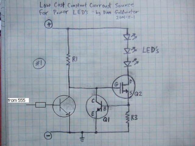
Description
The extra transistor switches off the LED when base current is supplied, so the PWM will toggle the LED's between 0mA and the current set by R3
and the Vbe of Q1.
However, unless you are expecting to see a large variation in supply voltage, or you have relatively little voltage headroom between your LED arry and
the supply, then this is over complicated and a simple resistor may well suffice.
Also note this is a relatively poor 'constant current' circuit; the voltage reference here is the Vbe of Q1 which will vary with
temperature (-2mv/degree C). Depending on the value of the resistor this could give a significant change in current within a typical automotive
temperature range e.g. a 50 degree Celsius temperature range would change current by about 0.1/0.6 * 100 = 17%.
|
|
|
tegwin
|
| posted on 23/11/11 at 09:40 AM |
|
|
That is quite interesting. Thankyou :-)
I am planning to drive a matrix of 1000 LEDs for photography purposes from a 12V battery.
I agree going the route of resistors would be simpler but it does not allow easy dimming and that many resistors would burn about 40w..which is a lot
more than the fet would drop isnt it?
------------------------------------------------------------------------------------------------------------------------
Would the last person who leaves the country please switch off the lights and close the door!
www.verticalhorizonsmedia.tv
|
|
|
DanP
|
| posted on 23/11/11 at 10:53 AM |
|
|
Hi
The FET is just a voltage controlled resistor it will dissipate exactly the same power as a resistor in its place. Power dissipated 'P' =
IV where I is the LEd current and V is the voltage dropped across the FET/ resistor (ie 12v minus the voltage dropped by the resistors in series which
is normally about 1.5v per LED)
Do you know the current drawn by the LEDs you want to use? Most normal LEDs are about 10-20ma max. if you really do want to run 1000 LEDs off a 12v
supply then what I would do is fit as many LEDs as you can in series to get about a 10V drop (prob 6) then parallel this up enough times to get all
1000 in, 1000/6 = 166 parallel led strips - then you would need a battery capable of supplying 166x20mA = 3.3A (quite a lot!)
Then either fit an FET and resistor or just a resistor per strip or one single component set capable of taking all of the combined current. Then you
can either set the resistor and leave it if you don't want to dim, or vary the gate voltage to the FET to dim it, or PWM the FET on and off to
set the brightness level (the resistor then just sets the max/relative brightness.
100 LEDs is quite a lot to solder btw! Have you considered looking for some sort of module that you can buy to do this job?
Cheers,
Dan
|
|
|
tegwin
|
| posted on 23/11/11 at 12:26 PM |
|
|
Hi Dan.
The LEDs are 3.4V 60ma jobbies. 1000 of them cost me a tenner... Yes, soldering them is going to be a ballache... but will cost a lot less than any
commercial jobbies..... even ebay from china doesnt seem to have suitably sized panels with the right colour LEDs on them.
I figure if I use a car type battery I can run them for a couple of hours. Might hook them up to a remote trigger so I can switch then on and off with
the shutter on the camera a bit like a flash.
------------------------------------------------------------------------------------------------------------------------
Would the last person who leaves the country please switch off the lights and close the door!
www.verticalhorizonsmedia.tv
|
|
|
coyoteboy
|
| posted on 23/11/11 at 02:01 PM |
|
|
quote:
I am planning to drive a matrix of 1000 LEDs for photography purposes from a 12V battery.
Good photography and LEDs don't mix as the light doesn't have a good spectral output, it has very un-natural peaks, even with modern LEDs.
|
|
|
MakeEverything
|
| posted on 23/11/11 at 03:33 PM |
|
|
Ive just run a simulation and if you change R3 for a variable resistor, it should work. I ran the simulation with a 20k variable resistor, but you
could use a 4k variable resistor.

Kindest Regards,
Richard.
...You can make it foolProof, but youll never make it Idiot Proof!...
|
|
|
02GF74
|
| posted on 23/11/11 at 04:19 PM |
|
|
quote:
Originally posted by coyoteboy
quote:
I am planning to drive a matrix of 1000 LEDs for photography purposes from a 12V battery.
Good photography and LEDs don't mix as the light doesn't have a good spectral output, it has very un-natural peaks, even with modern LEDs.
White LEDs are not white; they are blue LEDs with yellow phospor so emit blue/yellow mix, to the human eye it appears as white; sensor in digital
camera will not have same response as human eye.
|
|
|