locoboy
|
| posted on 21/9/12 at 08:04 PM |

|
|
Fastner and design help
Hi folks,
Again I am back here for ideas as I am struggling to overcome a problem and you guys have a broad range of experience of working with all different
types of fasteners.
I am trying to make a tilting platform that will tilt front and back and side to side, but.........in both planes at the same time if required.
The requirements are
It must be stable when in position
It must be able to move in both planes
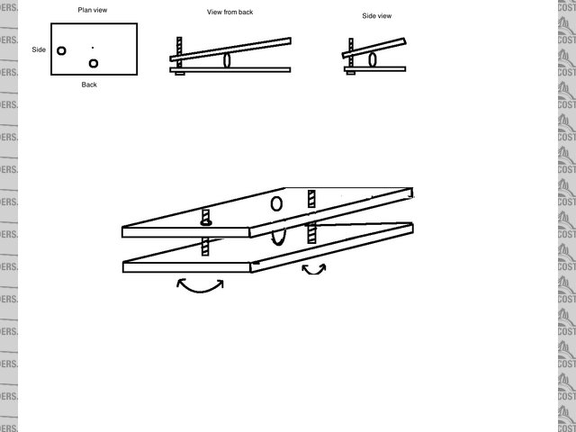
I have an idea as roughly sketched in the attached picture.
The Idea I have is to have a balljoint in the middle securing the two parts together and allow articulation.
The movement will be provided by 2 threaded bars one to provide front to back tilt and one to provide side to side tilt.
My concern is that when the top plate is angled, the threaded holes will not be aligned with the threaded rod and it will all bind up.
I really don't know where to go from here.........
it is to be remotely controlled and the screws would most likely be turned by servos.
Any ideas on how to overcome this or do you have any new ideas to achieve the same outcome?
Tilt platform
ATB
Locoboy
|
|
|
|
|
HowardB
|
| posted on 21/9/12 at 08:15 PM |
|
|
mount the nuts in gimbles,... then they can re-align as the plates move,...
what does it do? How big is it, and what are the forces involved. If it is only a very small load, and the force is always in compression, then throw
away the screw arrangement, and replace it with two cams (direct on the servos), one on each axis,...
hth
Howard
Fisher Fury was 2000 Zetec - now a 1600 (it Lives again  and goes zoom) and goes zoom)
|
|
|
locoboy
|
| posted on 21/9/12 at 08:33 PM |
|
|
Howard.
Thanks for the ideas.
having searched for gimbals I now understand what they are but cant see how they could actually be used in this application.
The overall size would be approx 8 inches x 6 inches.
Forces involved will not be a lot, maybe 2kg, but not always in compression, my first idea was a cam but the potential lack of compression and that
the cam may be reversed with the 2kg weight on it...
Col
ATB
Locoboy
|
|
|
HowardB
|
| posted on 21/9/12 at 08:59 PM |
|
|
I'll try and do a sketch,...
Howard
Fisher Fury was 2000 Zetec - now a 1600 (it Lives again and goes zoom)
|
|
|
bi22le
|
| posted on 21/9/12 at 09:41 PM |
|
|
I have many ideas and solutions for this as it is in my realm of work.
Springs can over come the 2kg negative and keep the ball in check.
How fast do the axis change and how do they change?
Im in a night club as i text this but will respond more tomorrow.
Track days ARE the best thing since sliced bread, until I get a supercharger that is!
Please read my ring story:
http://www.locostbuilders.co.uk/forum/13/viewthread.php?tid=139152&page=1
Me doing a sub 56sec lap around Brands Indy. I need a geo set up! http://www.youtube.com/watch?v=EHksfvIGB3I
|
|
|
matt_gsxr
|
| posted on 21/9/12 at 10:15 PM |
|
|
quote:
Originally posted by bi22le
Im in a night club as i text this but will respond more tomorrow.
Dedicated locosting? or crap nightclub?
|
|
|
Theshed
|
| posted on 22/9/12 at 07:56 AM |
|
|
If you have the "nuts" in or attached to the fixed/lower plate then you can use a ball/cup at the top with a circlip to retain the ball in
the cup.
|
|
|
MikeRJ
|
| posted on 22/9/12 at 08:59 AM |
|
|
How much articulation do you need? A UJ in the middle of the platform would provide lateral and rotational rigidity. A ball joint won't provide
any rotational rigidity which would complicate the design (you'd need something like a peg on one side and a slot in the other side to stop
rotation).
The adjusters could use small rod ends to allow for the angles they need to operate at since they will then only be loaded in tension or compression.
If you can arrange things so that one of the rod ends on each adjuster is mounted exactly in-line with the axes of the UJ then nothing should bind.
This may need brackets on the platform to drop the mounting points since the UJ will likely be mid way between the platforms.
|
|
|